Manual Chapter :
Common Elements for Profiles Tasks
Applies To:
Show Versions
BIG-IP APM
- 14.0.1, 14.0.0
Common Elements for Profiles Tasks
- On the Main tab, click .
- On the menu bar, expand or click a profile category and choose the type of profile you want to create.
- In the name column, click the system-supplieddnsprofile.The DNS properties list screen opens.
- In the name column, click the system-supplieddnsprofile.The DNS properties list screen opens.
- From theResponse Cachelist, selectEnabled.
- In the Hardware Acceleration area, from theProtocol Validationlist, selectEnabled.
- ClickUpdate.
- On the Main tab, click .The MS SQL Profiles list screen opens.
- On the Main tab, click .The Logging Profiles list screen opens.
- On the Main tab, click .The HTTP profile list screen opens.
- On the Main tab, click .The SMTPS profile list screen opens.
- On the Main tab, click .The Rewrite profile list appears.
- On the Main tab, click .The HTTP Compression profile list screen opens.
- On the Main tab, click .The HTTP Compression profile list screen opens.
- On the Main tab, click .The Web Acceleration profile list screen opens.
- On the Main tab, click .The FTP profile list screen opens.
- On the Main tab, click .The DNS profile list screen opens.
- On the Main tab, click .The DNS profile list screen opens.
- On the Main tab, click or .The DNS profile list screen opens.
- On the Main tab, click .The DNS list screen opens.
- In the Name column, click the name of the profile you want to modify.
- On the Main tab, click .The IIOP profile list screen opens.
- On the Main tab, click .The RTSP profile list screen opens.
- On the Main tab, click .The Diameter profile list screen opens.
- On the Main tab, click .The RADIUS profile list screen opens.
- On the Main tab, click .The SMTP profile list screen opens.
- On the Main tab, click .The iSession profile list screen opens.
- On the Main tab, click .The Profiles list screen opens.
- On the Main tab, click .The MAPI profile list screen opens.
- On the Main tab, click .The XML profile list screen opens.
- On the Main tab, click .The HTTP/2 profile list screen opens.
- On the Main tab, click .The HTTP/2 profile list screen opens.
- On the Main tab, click .The SPDY profile list screen opens.
- On the Main tab, click .The SPDY profile list screen opens.
- On the Main tab, click .The FIX profile list screen opens.
- On the Main tab, click .The IPsecALG profile list screen opens.
- On the Main tab, click .The Persistence profile list screen opens.
- In the Name column, click the name of the relevant persistence profile.
- For theMirror Persistencesetting, select the check box.
- On the Main tab, click .The Fast L4 screen opens.
- On the Main tab, click .The Fast HTTP profile list screen opens.
- On the Main tab, click .The HTTP Class profile list screen opens.
- On the Main tab, click .The TCP profile list screen opens.
- On the Main tab, click .The SIP profile list screen opens.
- On the Main tab, click .The UDP profile list screen opens.
- On the Main tab, click .The SCTP profile list screen opens.
- On the Main tab, click .The Client SSL profile list screen opens.
- On the Main tab, click .The Server SSL profile list screen opens.
- On the Main tab, click or .The Client SSL or Server SSL profile list screen opens.
- On the Main tab, click .The OCSP Stapling list screen opens.
- Scroll down toHandshake Timeoutand select theCustomcheck box.Additional settings become available.
- To limit the timeout to a number of seconds, selectSpecifyfrom the list, and type the required number in thesecondsfield.In the list, the valueIndefinitespecifies that the system continue trying to establish a connection for an unlimited time. If you selectIndefinite, thesecondsfield is no longer available.
- On the Main tab, click .The Profiles list screen opens.
- On the Main tab, click .The Request Logging profile list screen opens.
- On the Main tab, click .The DNS Logging profile list screen opens.
- On the Main tab, click .The DNS Logging profile list screen opens.
- On the Main tab, click or .The DNS Logging profile list screen opens.
- On the Main tab, click .The OneConnect profile list screen opens.
- On the Main tab, click .The SplitSession Client profile list screen opens.
- On the Main tab, click .The SplitSession Server profile list screen opens.
- On the Main tab, click .TheHTTP Proxy Connectprofile list screen opens.
- On the Main tab, click .The Client LDAP list screen opens.
- On the Main tab, click .The Server LDAP list screen opens.
- On the Main tab, click .IfAnalyticsis not listed, this indicates that Application Visibility and Reporting (AVR) is not provisioned, or you do not have rights to create profiles.The HTTP Analytics screen opens.
- In the Logging and Reporting area, select theAVR Statistics Sample Ratecheck box.TheEnabled 1/ 1 queries sampledfield displays.
- In theEnabled 1/ 1 queries samplefield, change the1to the number of queries from which the system takes one sample.0No DNS requests are stored in the Analytics database.1All DNS requests are stored in the Analytics database.n>1Every nth DNS request is stored in the Analytics database.
- For theStatistics Logging Typesetting, clickExternal.
- From thePublisherlist, select the publisher that contains the destination to which you want the BIG-IP system to send the statistics.
- For theStatistics Logging Typesetting, verify thatInternalis selected. If it is not, select it.SelectingInternalcauses the system to store statistics locally, and you can view the charts on the system by starting at the Main tab, and clicking .
- For theTransaction Sampling Ratiosetting, specify whether the system learns information from every transaction (specifyall), or performs traffic sampling (specify1 of every ntransactions).A high sampling rate (such as99) results in less precise statistical data but improves system performance. Adjust the sampling ratio according to expected TPS and quantity of entities.You can change this setting only on the default Analytics profile.
- In the Associated Virtual Servers area, specify the virtual servers for which to capture application statistics:
- For theVirtual Serverssetting, clickAdd.
- From the Select Virtual Server popup that opens, select the virtual servers to include and then clickDone.
Only virtual servers previously configured with an HTTP profile display in the list (because the data being collected applies to HTTP traffic). Also, you can assign only one HTTP Analytics profile to a virtual server; therefore, the list displays only virtual servers that have not been assigned an Analytics profile.Special considerations apply if using Analytics on a BIG-IP system with both Application Security Manager and Access Policy Manager, where security settings (in Portal Access webtop or an iRule) redirect traffic from one virtual server to another. In this case, you need to attach the HTTP Analytics profile to the second virtual server to ensure that the charts show accurate statistics. - Specify the virtual servers for which to capture traffic:
- In theVirtual Serverssetting, clickAdd.
- From the Select Virtual Server list that displays, select the virtual servers and clickDone.
Only previously configured virtual servers display in the list. - In the Statistics Gathering Configuration area, forCollected Metrics, select additional statistics you want the system to collect from the requests:OptionDescriptionMax TPS and ThroughputCollects and logs statistics regarding the maximum number of transactions occurring per second (TPS) and the amount of traffic moving through the system.Maximum request and response throughput is collected and recorded separately. Each value is then displayed separately when you drill down into details of Transaction Outcomes ().HTTP Timing (RTT, TTFB, Duration)Collects and logs statistics regarding the HTTP request and response times, including round-trip time, time to first byte and overall transaction duration time.Page Load TimeCollects and logs statistics regarding the time it takes an application user to get a complete response from the application, including network latency and completed page processing.End-user response times and latencies can vary significantly based on geographic location and connection types.User SessionsCollects and logs statistics regarding the number of unique user sessions. ForTimeout, select the allowed minutes of user inactivity before the system considers the session to be over.ForCookie Secure Attribute, specify whether to secure session cookies:
- Always, the secure attribute is always added to the session cookie.
- Never, the secure attribute is never added to the session cookie.
- Only SSL, the secure attribute is added to the session cookie only when the virtual server has a client SSL profile (the default value).
By default, the system collects many metrics, including TPS, throughput, server latency, response time, network latency. You can select the metrics here, in addition to the ones already collected, once the Analytics profile is attached to one or more virtual servers. - In the Statistics Gathering Configuration area, forCollected Entities, select additional entities to collect statistics for each request.By default, the system collects many entity statistics, including virtual servers, pool members, browser names, operating system, and so on. You can select the ones here in addition to the ones already collected once the Analytics profile is attached to one or more virtual servers.When you selectURLs,Countries,Client IP AddressesorClient Subnetsyou have additional options configure specific statistics filtering options.OptionDescriptionURLsSaves the URLs that were requested.CountriesSaves the name of the country where the request came from, and is based on the client IP address criteria.Client IP AddressesSaves the IP address where the request originated. The address saved also depends on whether the request has an XFF (X-forwarded-for) header and whether the HTTP profile accepts XFF headers.Client SubnetsSaves statistics for predefined client subnets. Client subnets can be added in the Subnets area of the default HTTP Analytics profile.Response CodesSaves HTTP response codes that the server returned in response to requests.User AgentsSaves information about browsers making the request.MethodsSaves HTTP methods in requests.OS and BrowsersSaves information about the operating system and browser making the request.
- In the Statistics Gathering Configuration area, forCollect URLs, you can configure whether the system collects traffic from all or from specific URLs.
- SelectAllto collect traffic from all URLs.By default, the system collects traffic from all URLs, when you selectURLsfrom theCollected Entitieslist.
- SelectOnlyto collect traffic from specific URLs.
- Specify the URLs for which to capture traffic and clickAdd. You can add up to 10 URLs to the list.If you selectOnlyand leave the list empty, the system collects traffic data from all URLs.
- In the Statistics Gathering Configuration area, forCollect Countries, you can configure whether the system collects traffic from all or from specific countries.
- SelectAllto collect traffic from all countries.By default, the system collects traffic from all countries, when you selectCountriesfrom theCollected Entitieslist.
- SelectOnlyto collect traffic from specific countries.
- Specify the countries for which to capture traffic. Select from the Available Countries list and use the arrow keys to move each country to the Selected Countries list. You can add up to 10 countries to the Selected list.If you selectOnlyand leave the list empty, the system collects traffic data from all countries.
- In the Statistics Gathering Configuration area, forCollect Client IP Addresses, you can configure whether the system collects traffic from all or from specific client IPs.
- SelectAllto collect traffic from all client IP addresses.By default, the system collects traffic from all client IPs, when you selectClient IP Addressesfrom theCollected Entitieslist.
- SelectOnlyto collect traffic from specific client IP addresses.
- Specify the client IP addresses for which to capture traffic and clickAdd. You can add up to client IP addresses to the list.If you selectOnlyand leave the list empty, the system collects traffic data from all client IP addresses.
- In the Statistics Gathering Configuration area, forCollect Client Subnets, you can configure whether the system collects traffic from all or from specific client subnet IPs.
- SelectAllto collect traffic from all subnets.By default, the system collects traffic from all subnets, when you selectClient Subnetsfrom theCollected Entitieslist.
- SelectOnlyto collect traffic from specific subnets.
- Specify the subnet IPs for which to capture traffic and clickAdd. You can add up to 10 subnet IPs to the list.You can filter the listed subnets by one type of IP protocol. Adding both IPv4 and IPv6 protocols results in an error.If you selectOnlyand leave the list empty, the system collects traffic data from all subnets.
- If one of theTraffic Capturing Logging Typecheck boxes is selected, in the Capture Filter area, adjust the settings to specify criteria to determine what application traffic to capture.You can use the captured information for troubleshooting purposes.
- If you want the system to send email notifications, review theSMTP Configurationfield to ensure that a configuration is specified and not the valueNone.You can configure SMTP only in the default Analytics profile. If it is not configured, you can save the profile and edit the default profile where you can select an existing SMTP configuration or create a new one. (If you click theanalyticslink without saving the new profile you are working on, you will lose the unsaved changes.)
- For theNotification Typesetting, select how you want the system to send alerts and notifications.SyslogSelectSyslogif you want the system to send notification and alert messages to the local log system. You can view the messages on the screen.SNMPSelectSNMPif you want the system to send notification and alert messages as SNMP traps. You can create the trap by clickingConfiguration can be found here( ). Enabling SNMP automatically sets up Syslog notifications, too.E-mailSelectE-mailif you want the system to send notification and alert messages to email addresses. Type each email address in theNotification E-Mailsfield, and clickAddto create the list. This option requires that the default analytics profile includes an SMTP configuration.When you select a notification type, the screen displays the Alerts and Notifications Configuration area, where you can indicate the criteria for alerts and notifications.
- ClickCreate.The Create New Logging Profile screen opens.
- ClickCreate New Profile.The Create New Profile Rewrite pop-up screen opens.
- ClickCreate.The New Authentication Profile screen opens.
- ClickCreate.The New Fast L4 profile screen opens.
- ClickCreate.The New DNS Profile screen opens.
- ClickCreate.The New DNS Logging profile screen opens.
- ClickCreate.The New HTTP Compression profile screen opens.
- ClickCreate.The New Diameter profile screen opens.
- ClickCreate.The New HTTP Profile screen opens.
- ClickCreate.The New FTP Profile screen opens.
- ClickCreate.The New SCTP Profile screen opens.
- ClickCreate.The New SMTP Profile screen opens.
- ClickCreate.The New SMTPS Profile screen opens.
- ClickCreate.The New HTTP Class Profile screen opens.
- ClickCreate.The New Web Acceleration Profile screen opens.
- ClickCreate.The New HTTP Analytics profile screen opens.
- ClickCreate.The New Server SSL Profile screen opens.
- ClickCreate.The New Client SSL Profile screen opens.
- ClickCreate.The New Client LDAP Profile screen opens.
- ClickCreate.The New Server LDAP Profile screen opens.
- ClickCreate.The New Request Logging Profile screen opens.
- ClickCreate.The New Persistence Profile screen opens.
- ClickCreate.The New HTTP/2 Profile screen opens.
- ClickCreate.The New SPDY Profile screen opens.
- ClickCreate.The New FIX Profile screen opens.
- ClickCreate.The New GTP Profile screen opens.
- ClickCreate.The New OneConnect Profile screen opens.
- ClickCreate.The New MS SQL Profile screen opens.
- ClickCreate.The New SplitSession Client Profile screen opens.
- ClickCreate.The New SplitSession Server Profile screen opens.
- ClickCreate.The New HTTP Proxy Connect Profile screen opens.
- ClickCreate.The new OCSP Stapling Profile screen opens.
- ClickCreate.
- ClickFinished.
- ClickUpdate.
- ClickDelete.
- Click the name of a profile.
- In theNamefield, type a unique name for the profile.
- From theParent Profilelist, retain the default value,clientldap.
- From theParent Profilelist, retain the default value,serverldap.
- From theParent Profilelist, retain the default value or select another existing profile of the same type.
- From theParent Profilelist, select the profile from which you want to inherit settings.The default profile is often used as the parent profile.The new profile inherits the values from the parent profile. If the parent is changed, the inherited values in the new profile also change.
- On the Main tab, click .The SIP transport config list screen opens.
- On the menu bar, clickRouter Profiles.The Router Profiles list screen opens.
- ClickCreate.The New SIP Router Profile screen opens.
- In theNamefield, type a unique name for the SIP router profile.
- From theOperation Modelist, selectLoad Balancing.
- In theMaximum Pending Messagesfield, type ...
- In theMaximum Pending Bytesfield, type ...
- For theStatic Routessetting, move routes that define how the BIG-IP system load balances SIP traffic from theAvailablelist to theSelectedlist.
- In theTransaction Timeout (seconds)field, type the number of seconds...
- On the menu bar, clickSession Profiles.The Session Profiles list screen opens.
- ClickCreate.The New SIP Session Profile screen opens.
- In theNamefield, type a unique name for the SIP session profile.
- In theMaximum Message Size (bytes)field, type ...
- In theMaximum Message Header Countfield, type ...
- In theCustom Viafield, type ...
- From thePersist Keylist, select the value the system uses for persistence of a SIP session. The options are:OptionDescriptionCall-IDThe system uses the value in the Call-ID header field in the SIP message.CustomThe system uses the value of a custom key specified in an iRule.Src-AddrThe system uses the originating IP address in the SIP message.
- From thePersist Typelist, select one of these options:OptionDescriptionSessionPersistence is enabled.NonePersistence is disabled.
- In thePersist Timeout (seconds)field, type the number of seconds before a SIP session persistence record expires.
- In theProfile Namefield, type a unique name for the Analytics profile.
- In the General Properties area, name the profiledns_express.
- In the General Properties area, name the profiledns_zxfr_dnssec.
- In the General Properties area, name the profiledns_zxfr.
- In theProfile Namefield, type a unique name for the Security Logging Profile.
- In theProfile Namefield, type a unique name for the profile.
- In the General Properties area, from theParent Profilelist, accept the defaultdnsprofile.
- On the Main tab, click .
- On the Main tab, click .
- On the Main tab, click .
- ClickCreate.The New DHCPv4 Profile screen opens.
- ClickCreate.The New DHCPv6 Profile screen opens.
- ClickCreate.The New Radius Profile screen opens.
- In theNamefield, type a unique name for the profile.
- From theParent Profilelist, select the defaultdhcpv4profile.
- From theParent Profilelist, select the defaultdhcpv6profile.
- From theParent Profilelist, select the defaultradiusaaaprofile.
- Select theCustomcheck box.
- In the Protocol and Proxy Settings Features area, make a selection from theDHCP Modelist.OptionDescriptionRelayWhen in relay mode, a virtual server relays Dynamic Host Control Protocol (DHCP) client requests and applies unicast IP addresses as the relayed message destination.ForwardWhen in forward mode, a virtual server forwards Dynamic Host Control Protocol (DHCP), and does not modify, client requests for an IP address to one or more DHCP servers.
- For theIdle Timeoutsetting, type the number of seconds that a BIG-IP DHCP connection is idle before the connection is eligible for deletion.
- For theMax Hopssetting, select theCustomcheck box to enable this option. Type the maximum expected number of relay agents that the messages should pass through, before reaching the DHCPv4 server.
- For theDefault TTLsetting, select theCustomcheck box to enable this option. Type the time to live (TTL) value that you want to set for each outgoing DHCP packet.
- For theTTL Decrement Amountsetting, select theCustomcheck box to enable this option. Type the amount that the DHCP virtual will use to decrement the TTL for each outgoing DHCP packet.
- For theDefault Lease Timesetting, select theCustomcheck box to enable this option. Type the time, in seconds, of the default value of the DHCPv4 lease time.
- For theTransaction Timeoutsetting, select theCustomcheck box to enable this option. Type the number of seconds, taken to internally process the messages.
- For theTransaction Timeoutsetting, select theCustomcheck box to enable this option. Type the number, in seconds, of the time taken for server to respond.
- If you want the DHCP module to insert option 82, for theInsert Relay Agent ID (Option 82)setting, select theCustomcheck box.
- If you want the DHCP module to insert option 37, for theInsert Remote ID (Option 37)setting, select theCustomcheck box .
- If you want the DHCP module to insert option 38, for theInsert Remote ID (Option 38)setting, select theCustomcheck box to enable this option .
- If you want the DHCP relay agent to remove option 82 from the server to client traffic, for theRemove Relay Agent ID From Client Messagessetting, select theCustomcheck box to enable this option.
- If you want the DHCP relay agent to remove option 37 from the server to client traffic, for theRemove Subscriber Agent ID From Client Messagessetting, select theCustomcheck box.
- If you want the DHCP module to remove option 38 from the server to client traffic, for theRemove Relay Agent ID From Client Messagessetting, select theCustomcheck box.
- From theSubscriber Discoverylist, selectEnabled. Then, for theSubscriber ID Formatsetting, select the format you want to implement.FormatDescriptionMAC AddressUses the subscriber ID as the MAC address through which the subscriber ID goes through.Relay Agent Option: Suboption ID 1Uses the relay agent first option suboption ID.Relay Agent Option: Suboption ID 1 + <Separator> + Suboption ID 2Uses the relay agent first and second suboption IDs.MAC Address + <Separator> + Relay Agent Option: Suboption ID 1Uses the MAC Address and the relay agent first suboption ID.MAC Address + <Separator> + Relay Agent Option: Suboption ID 1 <Separator> + Suboption ID 2Uses the relay agent first option suboption ID.TCL ExpressionUses the TCL expression to format the subscriber ID.
- From theAuthentication Settingslist, selectEnabled. Then, select the virtual server name from theAuthentication Virtuallist. Select theUser Name Formatyou want to implement.TheUser Name Formathas the same options as theSubscriber ID Format, in the Subscriber Discovery setting.
- From theSubscriber Discoverylist, selectEnabled. Then, for theSubscriber ID Formatsetting, select the format you want to implement.FormatDescriptionMAC AddressUses the subscriber ID as the MAC address through which the subscriber ID goes through.MAC Address + <Separator> + Option 37Uses the MAC address and the remote ID relay agent option.MAC Address + <Separator>+ Option 37 <Separator> + Option 38Uses the MAC address, the remote ID relay agent option and the subscriber ID option.MAC Address + <Separator> + Option 38Uses the MAC address and the subscriber ID option.Option 37Uses the remote ID relay agent option.Option 37 <Separator> + Option 38:Uses the remote ID relay agent option and the subscriber ID option.Option 38Uses the subscriber ID option.TCL ExpressionUses the TCL expression to format the subscriber ID.
- From theAuthentication Settingslist, selectEnabled. Then, select the virtual server name from theAuthentication Virtuallist. Select theUser Name Formatyou want to implement.TheUser Name Formathas the same options as theSubscriber ID Format, in the Subscriber Discovery setting.
- For theSecretsetting, select theCustomcheck box to enable this option. Type the shared secret of the RADIUS server used for authentication.
- For thePasswordsetting, select theCustomcheck box to enable this option. Type the password of the RADIUS AAA profile for RADIUS server authentication.
- For theRetransmission Timeoutsetting, select theCustomcheck box to enable this option. Type the number of seconds to wait before resending authentication or accounting messages to the RADIUS server.
- From theParent Profilelist, select the defaultftpprofile.
- From theParent Profilelist, select a parent profile.
- For theInherit Parent Profilesetting, select the check box.This optimizes data channel traffic.
- Select theCustomcheck box.
- If you want to disable IPv6 translation, in the Settings area, clear theTranslate Extendedcheck box.
- Retain theData Portsetting default value of20.
- To enable FTP security checks, select theProtocol Securitycheck box.The Protocol Security tab opens.
- In theOut Streamsfield, type a value for the number of outbound streams.Ensure that this value equals the value requested by the servers when the server-side connection is established.A value of2, or greater, enables SCTP multistreaming functionality.
- In theIn Streamsfield, type a value for the number of inbound streams.Ensure that this value equals the value requested by the servers when the server-side connection is established.A value of2, or greater, enables SCTP multistreaming functionality.
- Configure the client-side multihoming settings.
- From theClient Side Multi-hominglist, selectEnabledto enable SCTP multihoming for clients.When enabled, this setting enables SCTP clients to connect to a virtual server over multiple IP interfaces.TheSecondary Addressessetting appears.
- For theSecondary Addressessetting, in theDestination Addressfield, type a valid destination address for any virtual server that uses this SCTP profile.
- ClickAdd.Repeat the addition of each destination address that you want to provide to SCTP clients.
- From theServer Side Multi-hominglist, selectEnabledto enable SCTP multihoming for servers.
- From theParent Profilelist, select the existing SMTP profile from which you want the new profile to inherit settings. The default issmtp.
- Select theProtocol Securitycheck box to enable SMTP security checks.
- From theParent Profilelist, select a profile from which the new profile inherits properties.
- For theParent Profilesetting, confirm thatsslappears.
- Select theCustomcheck box.
- Select theCustomcheck box.
- Select theCustomcheck box.
- Next toSettings, select theCustomcheck box.
- Next toLog Settings, select theCustomcheck box.
- From theConfigurationlist, selectAdvanced.
- Select theCustomcheck box.The settings become available for change.
- Next to Client Authentication, select theCustomcheck box.The settings become available.
- From theCertificatelist, select the name of an SSL certificate on the BIG-IP system.If the BIG-IP system is part of a DSC Sync-Failover group, always select a non-default certificate name, and ensure that this same certificate name is specified in every instance of this SSL profile in the device group. Taking these actions helps to ensure that SSL handshakes are successful after a failover event.
- From theKeylist, select the name of an SSL key on the BIG-IP system.If the BIG-IP system is part of a DSC Sync-Failover group, always select a non-default key name, and ensure that this same key name is specified in every instance of this SSL profile in the device group. Taking these actions helps to ensure that SSL handshakes are successful after a failover event.
- In thePass Phrasefield, select a pass phrase that enables access to the certificate/key pair on the BIG-IP system.
- From theChainlist, select the name of an SSL chain on the BIG-IP system.
- Select theCustomcheck box forServer Authentication.
- Modify the settings, as required.
- Modify other settings, as required.
- Configure all other profile settings as needed.
- For theProxy SSLsetting, select the check box.
- Select theCustomcheck box for the Request Settings area.
- Select theCustomcheck box for the Response Settings area.
- Select the check box for the applicable profile.
- In theProfile Namefield, type a unique name for the MS SQL profile, for example,mssql_user_access.
- In theProfile Namefield, type a unique name for the MS SQL profile, for example,mssql_command_access.
- From theRead/Write Splitlist, selectBy Command.
- From theRead/Write Splitlist, selectBy User.
- From theRead Poollist, select the pool of MS SQL database servers to which the system sends read-only requests.
- From theWrite Poollist, select the pool of MS SQL database servers to which the system sends write requests.
- In theWrite Persist Timerfield, type the number of milliseconds, after a connection has switched to the write pool, that the connection continues to persist to the write pool.Use the value-1to persist the connection to the write pool for the duration of the connection.If you set this to a value other than-1, the value must be greater than the amount of time required for the primary and secondary database servers to synchronize with one another.
- From theUsers Can Write By Defaultlist, selectYesto give write access to all users, except those in theRead-Only Userslist.
- From theUsers Can Write By Defaultlist, selectNoto give write access only to users in theWrite-Enabled Userslist.
- In theRead-Only Usersarea, add users to whom you want to provide read-only access to the database.
- In theWrite-Enabled Usersarea, add users to whom you want to provide write access to the database.
- In the DNS Traffic area, from theDNS Securitylist, selectEnabled.
- In the DNS Traffic area, from theDNS Security Profile Namelist, select the name of the DNS firewall profile.
- In the Denial of Service Protection area, from theRapid Response Modelist, selectDisabled, until a DNS flood attack occurs. At that time, enable this setting, and select an action from theRapid Response Last Actionlist.When you enable this setting, all other DNS features are disabled, except DNS Express.
- In the Denial of Service Protection area, from theRapid Response Modelist, selectEnabled.Enable this setting after a DNS flood attack occurs. When you enable it, all other DNS features are disabled, except for DNS Express and global server load balancing (GSLB), unless theRapid Response Last Actionis set toAllow.
- In the Denial of Service Protection area, from theRapid Response Last Actionlist, select an option to protect your network:OptionDescriptionAllowBIG-IP system sends non-matching DNS queries along the regular packet processing pathDropBIG-IP system drops the message without sending a response to the client. This is the default value.No ErrorBIG-IP system returns NOERROR response to the client..NX DomainBIG-IP system returns non-existent name response to the client.RefuseBIG-IP system returns REFUSED response to the client.TruncateBIG-IP system truncates the response to the client.
- In the DNS Features area, from theGSLBlist, accept the default valueEnabled.
- In the DNS Features area, from theGSLBlist, selectDisabled.
- In the DNS Features area, from theDNS IPv6 to IPv4list, select how you want the system to handle IPv6 to IPv4 address mapping in DNS queries and responses.OptionDescriptionDisabledThe BIG-IP system does not map IPv4 addresses to IPv6 addresses.ImmediateThe BIG-IP system receives an AAAA query and forwards the query to a DNS server. The BIG-IP system then forwards the first good response from the DNS server to the client. If the system receives an A response first, it appends a 96-bit prefix to the record and forwards it to the client. If the system receives an AAAA response first, it simply forwards the response to the client. The system disregards the second response from the DNS server.SecondaryThe BIG-IP system receives an AAAA query and forwards the query to a DNS server. Only if the server fails to return a response does the BIG-IP system send an A query. If the BIG-IP system receives an A response, it appends a 96-bit user-configured prefix to the record and forwards it to the client.v4 OnlyThe BIG-IP system receives an AAAA query, but forwards an A query to a DNS server. After receiving an A response from the server, the BIG-IP system appends a 96-bit user-configured prefix to the record and forwards it to the client.Select this option only if you know that all your DNS servers are IPv4 only servers.If you selectedImmediate,Secondary, orV4 Onlytwo new fields display.
- From theDNS IPv6 to IPv4list, specify how you want the system to handle IPv6 to IPv4 address mapping in DNS queries and responses.OptionDescriptionDisabledThe BIG-IP system does not map IPv4 addresses to IPv6 addresses.ImmediateThe BIG-IP system receives an AAAA query and forwards the query to a DNS server. The BIG-IP system then forwards the first good response from the DNS server to the client. If the system receives an A response first, it appends a 96-bit prefix to the record and forwards it to the client. If the system receives an AAAA response first, it simply forwards the response to the client. The system disregards the second response from the DNS server.SecondaryThe BIG-IP system receives an AAAA query and forwards the query to a DNS server. Only if the server fails to return a response does the BIG-IP system send an A query. If the BIG-IP system receives an A response, it appends a 96-bit user-configured prefix to the record and forwards it to the client.v4 OnlyThe BIG-IP system receives an AAAA query, but forwards an A query to a DNS server. After receiving an A response from the server, the BIG-IP system appends a 96-bit user-configured prefix to the record and forwards it to the client.Select this option only if you know that all your DNS servers are IPv4 only servers.If you selectedImmediate,Secondary, orV4 Only, two new fields display.
- In the DNS Features area, in theIPv6 to IPv4 Prefixfield, specify the prefix the BIG-IP system appends to all A query responses to an IPv6 request.
- In theIPv6 to IPv4 Prefixfield, specify the prefix the BIG-IP system appends to all A query responses to an IPv6 request.
- In the DNS Features area, from theIPv6 to IPv4 Additional Section Rewritelist, select an option to allow improved network efficiency for both Unicast and Multicast DNS-SD responses.OptionDescriptionDisabledThe BIG-IP system does not perform additional rewrite.v4 OnlyThe BIG-IP system accepts only A records. The system appends the 96-bit user-configured prefix to a record and returns an IPv6 response to the client.v6 OnlyThe BIG-IP system accepts only AAAA records and returns an IPv6 response to the client.AnyThe BIG-IP system accepts and returns both A and AAAA records. If the DNS server returns an A record in the Additional section of a DNS message, the BIG-IP system appends the 96-bit user-configured prefix to the record and returns an IPv6 response to the client.
- From theIPv6 to IPv4 Additional Section Rewritelist, select an option to allow improved network efficiency for both Unicast and Multicast DNS-SD responses.OptionDescriptionDisabledThe BIG-IP system does not perform additional rewrite.v4 OnlyThe BIG-IP system accepts only A records. The system appends the 96-bit user-configured prefix to a record and returns an IPv6 response to the client.v6 OnlyThe BIG-IP system accepts only AAAA records and returns an IPv6 response to the client.AnyThe BIG-IP system accepts and returns both A and AAAA records. If the DNS server returns an A record in the Additional section of a DNS message, the BIG-IP system appends the 96-bit user-configured prefix to the record and returns an IPv6 response to the client.
- In the DNS Features area, from theDNS Expresslist, retain the default valueEnabled.
- In the DNS Features area, from theDNS Expresslist, selectDisabled.
- In the DNS Features area, from theDNSSEClist, selectEnabled.
- In the DNS Features area, from theDNSSEClist, selectDisabled.
- In the DNS Traffic area, from theZone Transferlist, selectEnabled.
- In the DNS Features area, from theUnhandled Query Actionslist, select how you want the BIG-IP system to handle a query that is not for a wide IP or DNS Express zone.OptionDescriptionAllowThe BIG-IP system forwards the query to a DNS server or a member of a pool of DNS servers. Note that if the pool is not associated with a listener and theUse BIND Server on BIG-IPoption is set toenabled, queries are forwarded to the local BIND server. (Allow is the default value.)DropThe BIG-IP system does not respond to the query.RejectThe BIG-IP system returns the query with the REFUSED return code.HintThe BIG-IP system returns the query with a list of root name servers.No ErrorThe BIG-IP system returns the query with the NOERROR return code.
- In the DNS Features area, from theUnhandled Query Actionslist, selectAllow.The BIG-IP system forwards zone transfer requests to a DNS server or a member of a pool of DNS servers.
- In the DNS Features area, from theUse BIND Server on BIG-IPlist, selectEnabled.Enable this setting only when you want the system to forward non-wide IP queries to the local BIND server on BIG-IP DNS.
- From theUse BIND Server on BIG-IPlist, selectEnabled.Enable this setting only when you want the system to forward non-wide IP queries to the local BIND server on BIG-IP DNS.
- In the DNS Features area, from theUse BIND Server on BIG-IPlist, selectDisabled.
- In the DNS Features area, make a selection from theUse BIND Server on BIG-IPlist.OptionDescriptionEnabledEnable this setting only when you want the system to forward non-wide IP queries to the local BIND server on the BIG-IP DNS.DisabledDisable this setting when you want the system to forward non-wide IP queries to a DNS server behind BIG-IP DNS.
- In the DNS Features area, make a selection from theRecursion Desiredlist.OptionDescriptionEnabledBIG-IP accepts DNS queries with the recursion bit set.DisabledBIG-IP does not accept DNS queries with the recursion bit set. When you configure BIG-IP to be an authoritative nameserver for an external web site, disable this option as a security measure to prevent denial of service attacks.
- In the DNS Features area, make a selection from theDNS Cachelist.When you enable theDNS Cacheoption, you must also select a name from theDNS Cache Namelist.OptionDescriptionEnabledEnable this setting when you want to cache the DNS responses handled by the virtual servers associated with this profile.DisabledDisable this setting when you want to debug the system. When you disable this setting, the profile retains the association with the DNS cache in theDNS Cache Namefield, but the system does not cache DNS responses.
- From theRate Limitinglist, selectEnabled.When you enable this setting, you must also select a profile from theRate Limiting Profilelist.
- From theRate Limiting Profilelist, select a profile based on your rate limited license.
- In the DNS Features area, from theDNS Cachelist, selectEnabled.When you enable theDNS Cacheoption, you must also select a DNS cache from theDNS Cache Namelist.
- In the DNS Features area, from theDNS Cachelist, selectDisabled.
- In the DNS Features area, from theDNS Cache Namelist, select the DNS cache that you want to associate with this profile.You can associate a DNS cache with a profile, even when theDNS Cacheoption, isDisabled.
- In the Logging and Reporting area, from theLogginglist, selectEnabled.
- In the Logging and Reporting area, from theLogginglist, selectDisabled.
- In the Logging and Reporting area, from theProfilelist, select a custom DNS Logging profile.
- In the Log Settings area, from theLogging Profilelist, select a custom Logging profile.
- In the DNS Security area, from thePublisherlist, select a destination to which the BIG-IP system sends DNS log entries.
- From theLog Publisherlist, select a destination to which the BIG-IP system sends log entries.You can specify publishers for other DoS types in the same profile, for example, for DNS, Network, or Application DoS Protection.
- If you want the BIG-IP system to log all DNS queries, for theLog Queriessetting, ensure that theEnabledcheck box is selected.
- If you want the BIG-IP system to log all DNS responses, for theLog Responsessetting, select theEnabledcheck box.
- If you want the BIG-IP system to include the query ID sent by the client in the log messages, for theInclude Query IDsetting, select theEnabledcheck box.
- ForActions, select theCustomcheck box.The settings in theActionsarea become available for configuring.
- From theHostslist, select and configure one of the following options, as applicable:
- Match All
- Match Only
- From theURI Pathslist, select and configure one of the following options, as applicable:
- Match All
- Match Only
- From theHeaderslist, select and configure one of the following options, as applicable:
- Match All
- Match Only
- From theCookieslist, select and configure one of the following options, as applicable:
- Match All
- Match Only
- From theSend Tolist, select and configure one of the following options, as applicable:
- None
- Pool
- Redirect to
- From theApplication Acceleration Managerlist, selectAccelerate.Configuring theHTTP Classprofile to accelerate traffic with the Application Acceleration Manager overridesWeb Accelerationprofile settings on the virtual server.
- In theWebAcceleratorlist, selectBypass.Configuring theHTTP Classprofile to bypass theWeb Applicationapplication overridesWeb Accelerationprofile settings on the virtual server.
- From theParent Profilelist, select one of the following profiles:
- httpcompression.
- wan-optimized-compression.
- From theHTTP Compression Profilelist, select one of the following profiles:
- httpcompression
- wan-optimized-compression
- A customized profile
- For theFile Typessetting, specify whether you want to create a list of allowed or disallowed file types:
- To create a list of file types that are permitted in requests, selectDefine Allowed.
- To create a list of file types not permitted, selectDefine Disallowed.
- For theFile Typessetting, specify the file types to allow or disallow in a request:
- Select file types from theAvailablelist, and move them to theAllowedorDisallowedlist.
- Add a new file type: type the name in theFile Typefield, clickAddto add it to theAvailablelist, and move it to the list.
If the profile is case-sensitive, the file types are case-sensitive. For example,jspandJSP> will be treated as separate file types. - From theWeb Acceleration Profilelist, select one of the following profiles:
- optimized-acceleration
- optimized-caching
- webacceleration
- A customized profile
- From theWeb Acceleration Profilelist, select one of the following profiles with an enabled application:
- optimized-acceleration
- optimized-caching
- webacceleration
- A customized profile
- From theRequest Logginglist, selectEnabled.
- In theTemplatefield, type the request logging parameters for the entries that you want to include in the log file.
- From theHSL Protocollist, select a high-speed logging protocol.
- From thePool Namelist, select the pool that includes the log server as a pool member.
- You can also configure the error response settings.
- From theRespond On Errorlist, selectEnabled.
- In theError Responsefield, type the error response strings that you want to include in the log file.These strings must be well-formed for the protocol serving the strings.
- Select theClose On Errorcheck box to drop the request and close the connection if logging fails.
- You can also configure the logging request errors settings.
- From theLog Logging Errorslist, selectEnabled.
- In theError Templatefield, type the request logging parameters for the entries that you want to include in the log file.
- From theHSL Error Protocollist, select a high-speed logging error protocol.
- From theError Pool Namelist, select a pool that includes the node for the error logging server as a pool member.
- From theHSL Poollist, select the name of the remote pool of servers to which you want the BIG-IP system to send DNS log entries.
- In the Response Settings area, from theResponse Logginglist, selectEnabled.
- Select theLog By Defaultcheck box.TheLog By Defaultcheck box is selected by default.
- In theTemplatefield, type the response logging parameters for the entries that you want to include in the log file.
- From theHSL Protocollist, select a high-speed logging protocol.
- From thePool Namelist, select the pool that includes the node log server as a pool member.
- Configure the logging request error settings.
- From theLog Logging Errorslist, selectEnabled.
- In theError Templatefield, type the response logging parameters for the entries that you want to include in the log file.
- From theHSL Error Protocollist, select a high-speed logging error protocol.
- From theError Pool Namelist, select a pool that includes the node for the error log server as a pool member.
- For theWA Applicationssetting, select an application in theAvailablelist and clickEnable.The application is listed in theEnabledlist.
- For theWA Applicationssetting, select an application in theEnabledlist and clickDisable.The Application Acceleration Manager application is listed in theDisabledlist.
- On the Main tab, click .The Classification screen opens.
- Scroll down to the Enforcement area.
- From theAllow Truncated Redirectlist, selectEnabledto forward HTTP traffic with missing trailing carriage returns to the client.
- In theMaximum Header Sizefield, type a size, in bytes, for the maximum acceptable size of a header.
- From theOversize Client Headerlist, selectPass Throughto pass through traffic to the server when theMaximum Header Sizevalue is exceeded by the client.
- From theOversize Server Headerlist, selectPass Throughto pass through traffic to the client when theMaximum Header Sizevalue is exceeded by the server.
- In theMaximum Header Countfield, type a maximum number of headers for the system to support.
- From theExcess Client Headerslist, selectPass Throughto pass through traffic to the server when theMaximum Header Countvalue is exceeded by the client.
- From theExcess Server Headerslist, selectPass Throughto pass through traffic to the client when theMaximum Header Countis exceeded by the server.
- From thePipeline Actionlist, select one of the following settings.AllowDefault. Enables clients to make requests, even when prior requests have not received a response. Destination servers must include support for pipelining.RejectRejects the request.Pass ThroughProvides identical functionality as theAllowsetting, until a pipelined request is received, whereupon pass-through functionality becomes active. This setting works around clients and servers that break standard HTTP request-response connection handling.
- From theUnknown Methodlist, select one of the following settings.AllowDefault. Allows the HTTP filter to process an unknown HTTP method.RejectRejects HTTP traffic that includes an unknown HTTP method.Pass ThroughPasses through HTTP traffic that includes an unknown HTTP method.
- Configure the list of known methods in theKnown Methodlist.Add a method to theEnabled Methodslist.
- In theAdd user defined methodfield, type the name of a method.
- ClickAdd. The method appears in theEnabled Methodslist.
Delete a method from theEnabled Methodslist.- Select a method in theEnabled Methodslist.
- ClickDelete.
If you delete a known method from theEnabled Methodslist, the BIG-IP system applies theUnknown Methodsetting to manage that traffic.Deleting a standard method, such asHEADorCONNECT, causes BIG-IP functionality that depends on detecting that method to fail to work correctly. - From thePolling Intervallist, selectSpecify, and type the maximum interval in seconds between polling by the s Flow agent of this profile.
- From theSampling Ratelist, selectSpecify, and type the ratio of packets observed at the virtual server associated with this profile to the samples you want the BIG-IP system to generate.For example, a sampling rate of 2000 specifies that one sample will be randomly generated for every 2000 packets observed.
- Select theProtocol Securitycheck box.
- In the HTTP, FTP, and SMTP Security area, from thePublisherlist, select the publisher that the BIG-IP system uses to log HTTP, FTP, and SMTP Security events.
- In the HTTP, FTP, and SMTP Security area, from thePublisherlist, selectlocal-db-publisher.
- In the DNS Security area, from thePublisherlist, select the publisher that the BIG-IP system uses to log DNS Security events.
- In the DNS Security area, from thePublisherlist, selectlocal-db-publisher.
- Select theLog Dropped Requestscheck box, to enable the BIG-IP system to log dropped DNS requests.
- Select theLog Filtered Dropped Requestscheck box, to enable the BIG-IP system to log DNS requests dropped due to DNS query/header-opcode filtering.The system does not log DNS requests that are dropped due to errors in the way the system processes DNS packets.
- Select theLog Malformed Requestscheck box to enable the BIG-IP system to log malformed DNS requests.
- Select theLog Rejected Requestscheck box to enable the BIG-IP system to log rejected DNS requests.
- Select theLog Malicious Requestscheck box to enable the BIG-IP system to log malicious DNS requests.
- From theStorage Formatlist, select how the BIG-IP system formats the log.OptionDescriptionNoneSpecifies the default format type in which the BIG-IP system logs messages to a remote Syslog server, for example:"management_ip_address","bigip_hostname","context_type","context_name","src_ip","dest_ip","src_port","dest_port","vlan","protocol","route_domain","acl_rule_name","action","drop_reasonField-ListAllows you to:
- Select, from a list, the fields to be included in the log.
- Specify the order the fields display in the log.
- Specify the delimiter that separates the content in the log. The default delimiter is the comma character.
User-DefinedAllows you to:- Select, from a list, the fields to be included in the log.
- Cut and paste, in a string of text, the order the fields display in the log.
- Select theNetwork Firewallcheck box.
- In the Network Firewall area, from thePublisherlist, select the publisher the BIG-IP system uses to log Network Firewall events.
- In the Network Firewall area, from thePublisherlist, select the IPFIX publisher the BIG-IP system uses to log Network Firewall events.
- SelectBlocked Loggingto guarantee logging of firewall events when logging traffic load is heavy, even to the detriment of system performance.
- Set anAggregate Rate Limitto define a rate limit for all combined network firewall log messages per second.Beyond this rate limit, log messages are not logged.Rate Limits are calculated per-second per TMM. Each TMM throttles as needed independently of other TMMs.
- In the Network Firewall area, from thePublisherlist, selectlocal-db-publisher.
- For theLog Rule Matchessetting, select how the BIG-IP system logs packets that match ACL rules. You can select any or all of the options.OptionEnables or disables logging of packets that match ACL rules configured with:Acceptaction=AcceptDropaction=DropRejectaction=RejectWhen an option is selected, you can configure a rate limit for log messages of that type.
- Select theLog IP Errorscheck box, to enable logging of IP error packets.When this setting is enabled, you can configure a rate limit for log messages of this type.
- Select theLog TCP Errorscheck box, to enable logging of TCP error packets.When this is enabled, you can configure a rate limit for log messages of this type.
- Select theLog TCP Eventscheck box, to enable logging of open and close of TCP sessions.When this is enabled, you can configure a rate limit for log messages of this type.
- In the IP Intelligence area, from thePublisherlist, select the publisher that the BIG-IP system uses to log source IP addresses, which are identified and configured for logging by an IP Intelligence policy.The IP Address Intelligence feature must be enabled and licensed.
- Set anAggregate Rate Limitto define a rate limit for all combined IP Intelligence log messages per second.Beyond this rate limit, log messages are not logged.Rate Limits are calculated per-second per TMM. Each TMM throttles as needed independently of other TMMs.
- In the IP Intelligence area, from thePublisherlist, selectlocal-db-publisher.The IP Address Intelligence feature must be enabled and licensed.
- Enable theLog Translation Fieldssetting to log both the original IP address and the NAT-translated IP address for Network Firewall log events.
- Enable theAlways Log Regionsetting to log the geographic location when a geolocation event causes a network firewall event.
- Enable theLog Translation Fieldssetting to log both the original IP address and the NAT-translated IP address for IP Intelligence log events.
- Enable theLog Geolocation IP Addresssetting to specify that when a geolocation event causes a network firewall action, the associated IP address is logged.
- In the Traffic Statistics area, from thePublisherlist, selectlocal-db-publisher.
- In the Traffic Statistics area, from thePublisherlist, select the publisher that the BIG-IP system uses to log traffic statistics.
- For theLog Timer Eventssetting, enableActive Flowsto log the number of active flows each second.
- For theLog Timer Eventssetting, enableReaped Flowsto log the number of reaped flows, or connections that are not established because of system resource usage levels.
- For theLog Timer Eventssetting, enableMissed Flowsto log the number of packets that were dropped because of a flow table miss. A flow table miss occurs when a TCP non-SYN packet does not match an existing flow.
- For theLog Timer Eventssetting, enableSYN Cookie (Per Session Challenge)to log the number of SYN cookie challenges generated each second.
- For theLog Timer Eventssetting, enableSYN Cookie (White-listed Clients)to log the number of SYN cookie clients whitelisted each second.
- In the Logging Profile Properties, select theDoS Protectioncheck box.The DoS Protection tab opens.
- In the DNS DoS Protection area, from thePublisherlist, select the publisher that the BIG-IP system uses to log DNS DoS events.You can specify publishers for other DoS types in the same profile, for example, for SIP or Application DoS Protection.
- In the SIP DoS Protection area, from thePublisherlist, select the publisher that the BIG-IP system uses to log SIP DoS events.You can specify publishers for other DoS types in the same profile, for example, for DNS or Application DoS Protection.
- On the Main tab, click .
- ClickCreate.
- On the right side of the screen, select theCustomcheck box.
- On the right side of the screen, select theCustomcheck box.
- In theNamefield, type a unique name for the profile.
- For theParent Profilesetting, retain the default value,icap.
- In theURIfield, type a URI in this format:icap://hostname:port/path.For example, using macro expansion, you can set theURIvalue to:
.icap://${SERVER_IP}:${SERVER_PORT}/virusScan - In theURIfield, type a URI in this format:icap://hostname:port/path.For example, using macro expansion, you can set theURIvalue to:icap://${SERVER_IP}:${SERVER_PORT}/videoOptimization
- In thePreview Lengthfield, type a length or retain the default value0.This value defines the amount of the HTTP request or response that the BIG-IP system offers to the ICAP server when sending the request or response to the server for adaptation. This value should not exceed the length of the preview that the ICAP server has indicated it will accept.
- In theHeader Fromfield, type a value for theFrom:ICAP header.
- In theHostfield, type a value for theHost:ICAP header.
- In theRefererfield, type a value for theReferer:ICAP header.
- In theUser Agentfield, type a value for theUser-Agent:ICAP header.
- ClickFinished.
- On the Main tab, click .
- ClickCreate.
- On the right-side of the screen, clear theCustomcheck box.
- In theNamefield, type a unique name for the profile.
- For theParent Profilesetting, retain the default value,requestadapt.
- For theEnabledsetting, retain the default value,Enabled.When you set this value toEnabled, the BIG-IP system forwards HTTP requests to the specified internal virtual server for adaptation.
- From theInternal Virtual Namelist, select the name of the internal virtual server that you previously created for forwarding HTTP requests to the pool of iCAP servers.
- In thePreview Sizefield, type a numeric value.This specifies the maximum size of the preview buffer. This buffer holds a copy of the HTTP request header and the data sent to the internal virtual server, in case the adaptation server reports that no adaptation is needed. Setting the preview size to0disables buffering of the request and should only be done if the adaptation server always returns a modified HTTP request or the original HTTP request.
- In theTimeoutfield, type a numeric value, in seconds.If the internal virtual server does not return a result within the specified time, a timeout error occurs. To disable the timeout, use the value0.
- From theService Down Actionlist, select an action for the BIG-IP system to take if the internal virtual server returns an error:
- SelectIgnoreto instruct the BIG-IP system to ignore the error and send the unmodified HTTP request to an HTTP server in the HTTP server pool.
- SelectDropto instruct the BIG-IP system to drop the connection.
- SelectResetto instruct the BIG-IP system to reset the connection.
- On the Main tab, click .
- ClickCreate.
- On the right-side of the screen, select theCustomcheck box.
- In theNamefield, type a unique name for the profile.
- For theParent Profilesetting, retain the default value,responseadapt.
- For theEnabledsetting, retain the default value,Enabled.When you set this value toEnabled, the BIG-IP system forwards HTTP responses to the specified internal virtual server for adaptation.
- From theInternal Virtual Namelist, select the name of the internal virtual server that you previously created for forwarding HTTP responses to the pool of iCAP servers.
- In thePreview Sizefield, type a numeric value.This specifies the maximum size of the preview buffer. This buffer holds a copy of the HTTP response header and the data sent to the internal virtual server, in case the adaptation server reports that no adaptation is needed. Setting the preview size to0disables buffering of the response and should only be done if the adaptation server always returns a modified HTTP response or the original HTTP response.
- In theTimeoutfield, type a numeric value.If the internal virtual server does not return a result within the specified time, a timeout error occurs. To disable the timeout, use the value0.
- From theService Down Actionlist, select an action for the BIG-IP system to take if the internal virtual server returns an error:
- SelectIgnoreto instruct the BIG-IP system to ignore the error and send the unmodified HTTP response to an HTTP server in the HTTP server pool.
- SelectDropto instruct the BIG-IP system to drop the connection.
- SelectResetto instruct the BIG-IP system to reset the connection.
- Set thePVA Accelerationfield toGuaranteed.
- Select theLoose Closecheck box only for a one-arm virtual server configuration.
- Set theTCP Close Timeoutsetting, according to the type of traffic that the virtual server will process.
- If you plan to useLate Bindingand either of theLoose InitiationandLoose Closecheck boxes are enabled, clear them both.TheLate Bindingfeature examines the first few packets in the FIX stream, and theLoose Initiationfeature makes it possible to skip those packets without any examination.
- Disable theHardware SYN Cookie Protectionfeature by clearing the check box.
- Enable theSoftware SYN Cookie Protectionfeature by selecting the check box.
- TheLate Bindingfeature makes it possible to choose a server pool based on data in the FIX header. An iRule in the virtual server parses the FIX header and selects the server pool. Select the check box to enableLate Binding.
- You can allow the iRule to explicitly determine when the flow is released from Layer 7 down to Layer 4. The iRule code can then perform additional computation before binding the connection to Layer 4. Enable this by selecting theExplicit Flow Migrationcheck box. When this feature is enabled, the flow is not released to Layer 4 until the iRule invokes theBIGTCP::release_flowcommand.By default, this is disabled and the flow drops down to Layer 4 immediately after the connection to the server is established.
- Use theClient Timeoutfield to determine how much time to allow for any client to send the first 2144 bytes of Layer 7information. In normal cases, this amount of data arrives immediately.
- From theTimeout Recoverylist, select an action that the profile should take in case of timeout. SelectDisconnectto drop the connection summarily, or selectFallbackto process the packet without parsing the Layer 7 fields. The fallback option sends any timed-out connection to the Virtual Server's default pool.
- For theSession Ticketsetting, select or clear the check box:
- Selecting the check box causes the BIG-IP system to use session tickets as a way to improve SSL performance.
- Clearing the check box prevents the BIG-IP system from using session tickets.
- In theProfile Namefield, type a name, such asmy_rewrite_profile.
- From theRewrite Modelist, selectURI Translation.
- From theParent Profilelist, selectrewrite.
- On the left pane, clickSettings.A list of request and response settings appears on the Settings tab.
- In the Settings box, select or clear the appropriate check boxes.Using the check boxes, you can rewrite and insert headers into HTTP requests, as well as rewrite headers and content in HTTP responses.
- On the left pane, clickURI Rules.An empty text box appears for displaying client-server URI mappings that you specify.
- In the URI Rules box, clickAdd.This displays the Create New Rewrite URI box.
- From theURI Typelist, select a URI type.
- ClickUpdate.
- ClickAdd.
- ClickAddagain.
- From theRule Typelist, selectBoth.
- In theClient URIbox, type a client path, such as/sales/.
- In theServer URIbox, type a server URI, such ashttp://appserver1.siterequest.com/sales/.You must include a scheme in the server URI that you specify.An example of a scheme ishttp.
- In theClient URIfield, type a client path, such as/marketing/.
- In theServer URIfield, type a server URI, such ashttp://appserver2.siterequest.com/marketing/.You must include a scheme in the server URI that you specify.An example of a scheme ishttp.
- ClickOK.This displays a mapping of the specified client path to the associated server scheme, host, and path.
- In theServer URIfield, type a server URI, such ashttp://appserver2.siterequest.com/sales/.
- ClickOK.
- In theNamecolumn, locate the Rewrite profile that you created previously and select the adjacent check box.
- Click theEditbutton.
- On the left pane, clickSet-Cookie Rules..This displays a list of client and server domain and path information.
- Type the relevant domain and path for both the client and the server.TBD
- On the Settings tab, .A list of settings appears.
- On the Main tab, click .
- In theProfile Namefield, type a name, such asmy_html_profile.
- From theParent Profilelist, select/Common/html.
- On the left pane, clickHTML Rules.
- Click theCreate Newbutton.
- Click theCreate New Profilebutton.
- On theCreate Newbutton, click the right arrow.
- SelectRemove Tag.The Create New Remove Tag Rule box appears.
- In theRule Namefield, type a name, such asmy_remove_img_tag_rule.
- Optionally, in theDescriptionfield, type a description of the rule, such asRemoves the img tag with the src attribute.
- On the left pane, clickContent Settings.This displays the Content Selection Type box.
- In theTypebox, specify the type of content you want the HTML rule to act on.A typical type of content to specify istext/html.
- On the left pane, clickMatch Settings.
- In theMatch Tag Namefield, type the name of the tag that you want to remove from the HTML content.An example of a tag to specify is the HTMLimgtag.
- In theMatch Attribute Namefield, type the name of the attribute associated with the tag that you specified for removal.An example of an attribute to specify is thesrcattribute for theimgtag.
- In theAvailable Ruleslist, locate the HTML rule that you want to enable, and select the adjacent check box.
- Using the Move button, move the selected HTML rule to theSelected Ruleslist.
- If the access policy uses On-Demand certificate authentication, perform these substeps:
- From theConfigurationlist, selectAdvanced.Additional settings display.
- Select theCustomcheck box forConfiguration.The settings become available.
- In theCiphersfield, type the name of a NATIVE cipher.The list of supported NATIVE ciphers includes these:
- RC4-MD5
- RC4-SHA
- AES128-SHA
- AES256-SHA
- DES-CBC3-SHA
- DES-CBC-SHA
- EXP1024-RC4-MD5
- EXP1024-RC4-SHA
- EXP1024-DES-CBC-SHA
- EXP-RC4-MD5
- EXP-DES-CBC-SHA
- NULL-MD5
- NULL-SHA
- Scroll down to the Client Authentication area.
- From theSSL Forward Proxylist, selectEnabled.
- In the SSL Forward Proxy area, select theCustomcheck box.
- From theSSL Forward Proxy Bypasslist, selectEnabled.When assigned to a virtual server, a client SSL profile and a server SSL profile both must specify the same value for this setting. You cannot change this setting in either profile while assigned to a virtual server. To change theSSL Forward Proxy Bypasssetting, you can create new profiles and add them to the virtual server, or detach the profiles from the virtual server, update them, and assign them to the virtual server again.Additional settings display.
- From theBypass Default Actionlist, selectInterceptorBypass.The default action applies to addresses and hostnames that do not match any entry specified in the lists that you specify. The system matches traffic first against destination IP address lists, then source IP address lists, and lastly, hostname lists. Within these, the default action also specifies whether to search the intercept list or the bypass list first.If you selectBypassand do not specify any additional settings, you introduce a security risk to your system.
- If you want to cache certificates by IP address and port number, select theCache Certificate by Addr-Portcheck box.
- From theReport Log Publisherlist, select the publisher for error messages and status reports.
- From theMessage Log Publisherlist, select the publisher for message logging.
- In theRate Sample Intervalfield, type the sample interval, in seconds, for the message rate.
- From theError Actionlist, select one of the following settings.
- Don't Forward(default) to drop a message with errors and not forward it.
- Drop Connectionto disconnect the connection.
- Select theQuick Parsingcheck box to parse the basic standard fields, and validate the message length and checksum.
- Select theResponse Parsingcheck box to parse the messages from the FIX server, applying the same parser configuration and error handling for the server as for the client.
- Select theFully Parse Logon Messagecheck box to fully parse the logon message, instead of using quick parsing.
- From theSender and Tag Substitution Data Group Mappinglist, select one of the following settings.SettingDescriptionNot Configured(default)Disables the tag substitution map between sender ID and tag substitution data group.SpecifyProvides theMapping Listsettings for you to configure as required.
- In theSenderfield, type a sender ID that represents the identity of the firm sending the message.Example:client1
- In theData Groupfield, type a tag substitution data group.Example:FIX_tag_map
- ClickAdd.
- Configure theMapping Listsettings, as required.
- In theSenderfield, type a sender ID that represents the identity of the firm sending the message.
- In theData Groupfield, type a tag substitution data group.
- ClickAdd.
- In theIngress Maximumfield, type the maximum number of messages that can be held in the GTP ingress queue.
- From theSTARTTLS Activation Modelist, selectRequire.
- From theSTARTTLS Activation Modelist, select a value:ValueDescriptionAllowThis value activates STARTTLS encryption for any client-side traffic that allows, but does not require, STARTTLS encryption.RequireThis value activates STARTTLS encryption for any client-side traffic that requires STARTTLS encryption. All messages sent to the BIG-IP system prior to STARTTLS activation are rejected with a message stating that a stronger authentication mechanism is required.NoneThis value refrains from activating STARTTLS encryption for client-side traffic. Note if you select this value, that you optionally can create an iRule that identifies client-side traffic that requires STARTTLS encryption and then dynamically activates STARTTLS for that particular traffic.
- From theSTARTTLS Activation Modelist, select a value:ValueDescriptionAllowThis value activates STARTTLS encryption for server-side traffic that allows, but does not require, STARTTLS encryption. In this case, the BIG-IP system only activates STARTTLS for server-side traffic when the BIG-IP system has activated STARTTLS on the client side and the client has acknowledged the activation.RequireThis value activates STARTTLS encryption for any server-side traffic that requires STARTTLS encryption. In this case, the BIG-IP system activates STARTTLS when a successful connection is made.NoneThis value refrains from activating STARTTLS encryption for server-side traffic. Note that if you select this value, you can optionally create an iRule that identifies server-side traffic that requires STARTTLS encryption and then dynamically activates STARTTLS for that particular traffic.
- Using theCertificate Key Chainsetting, specify both an ECDSA and an RSA certificate key chain:
- From theCertificatelist, select the name of a certificate with a key of type ECDSA.
- From theKeylist, select the name of an ECDSA key.
- From theChainlist, select the chain that you want to include in the certificate key chain.
- ClickAdd.
- Repeat this process and specify an RSA certificate key chain.
- For theCertificate Key Chainsetting, clickAdd.
- From theCertificatelist, select a certificate name.This is the name of a certificate that you installed on the BIG-IP system. If you have not generated a certificate request nor installed a certificate on the BIG-IP system, and the BIG-IP system is not part of a device service clustering (DSC) configuration, you can specify the name of the existing certificate nameddefault.If the BIG-IP system is part of a DSC Sync-Failover group, always select a non-default certificate name, and ensure that this same certificate name is specified in every instance of this SSL profile in the device group. Taking these actions helps to ensure that SSL handshakes are successful after a failover event.
- From theKeylist, select the name of the key associated with the certificate specified in the previous step.This is the name of a key that you installed on the BIG-IP system. If you have not installed a key on the BIG-IP system, and the BIG-IP system is not part of a device service clustering (DSC) configuration, you can specify the name of the existing key nameddefault.If the BIG-IP system is part of a DSC Sync-Failover group, always select a non-default key name, and ensure that this same key name is specified in every instance of this SSL profile in the device group. Taking these actions helps to ensure that SSL handshakes are successful after a failover event.
- From theChainlist, select the chain that you want to include in the certificate key chain.A certificate chain can contain either a series of public key certificates in Privacy Enhanced Mail (PEM) format or a series of one or more PEM files. A certificate chain can contain certificates for Intermediate certificate Authorities (CAs).The default self-signed certificate and the default CA bundle certificate are not appropriate for use as a certificate chain.
- For thePassphrasefield, type a string that enables access to SSL certificate/key pairs that are stored on the BIG-IP system with password protection.This setting is optional. For added security, the BIG-IP system automatically encrypts the pass phrase itself. This pass phrase encryption process is invisible to BIG-IP system administrative users.
- ClickAdd.
- For theCertificate Key Chainsetting, clickAdd.
- From theCertificatelist, select the name of a certificate with a key of type ECDSA.This is the name of a certificate that you installed on the BIG-IP system. If you have not generated a certificate request nor installed a certificate on the BIG-IP system, and the BIG-IP system is not part of a device service clustering (DSC) configuration, you can specify the name of the existing certificate nameddefault.If the BIG-IP system is part of a DSC Sync-Failover group, always select a non-default certificate name, and ensure that this same certificate name is specified in every instance of this SSL profile in the device group. Taking these actions helps to ensure that SSL handshakes are successful after a failover event.
- From theKeylist, select the name of an ECDSA key.This is the name of a key that you installed on the BIG-IP system. If you have not installed a key on the BIG-IP system, and the BIG-IP system is not part of a device service clustering (DSC) configuration, you can specify the name of the existing key nameddefault.If the BIG-IP system is part of a DSC Sync-Failover group, always select a non-default key name, and ensure that this same key name is specified in every instance of this SSL profile in the device group. Taking these actions helps to ensure that SSL handshakes are successful after a failover event.
- From theChainlist, select the chain that you want to include in the certificate key chain.A certificate chain can contain either a series of public key certificates in Privacy Enhanced Mail (PEM) format or a series of one or more PEM files. A certificate chain can contain certificates for Intermediate certificate Authorities (CAs).The default self-signed certificate and the default CA bundle certificate are not appropriate for use as a certificate chain.
- For thePassphrasefield, type a string that enables access to SSL certificate/key pairs that are stored on the BIG-IP system with password protection.This setting is optional. For added security, the BIG-IP system automatically encrypts the pass phrase itself. This pass phrase encryption process is invisible to BIG-IP system administrative users.
- ClickAdd.
- ClickAddand repeat the process for all certificate key chains that you want to specify. At a minimum, you must specify an RSA certificate key chain.Sample configuration with three key types specified
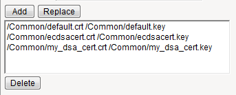 The result is that all specified key chains appear in the text box.
 - For theOCSP Staplingsetting, select the check box.This setting is optional. To enable OCSP stapling, you must first create an OCSP Stapling profile.
- Using theCertificate Key Chainsetting, specify a certificate key chain:
- From theCertificatelist, select a certificate name.This is the name of an RSA certificate that you installed on the BIG-IP system. If you have not generated a certificate request nor installed a certificate on the BIG-IP system, you can specify the name of an existing certificate,default.
- From theKeylist, select a key name.This is the name of an RSA key that you installed on the BIG-IP system. If you have not installed a key on the BIG-IP system, you can specify the name of an existing key,default.
- From theChainlist, select the chain that you want to include in the certificate key chain.A certificate chain can contain either a series of public key certificates in Privacy Enhanced Mail (PEM) format or a series of one or more PEM files. A certificate chain can contain certificates for Intermediate certificate Authorities (CAs).The default self-signed certificate and the default CA bundle certificate are not appropriate for use as a certificate chain.
- For thePassphrasefield, type a string that enables access to the SSL certificate/key pair.This setting is optional. For added security, the BIG-IP system automatically encrypts the pass phrase itself. This pass phrase encryption process is invisible to BIG-IP system administrative users.
- ClickAdd.The result is that the specified key chain appears in the text box.
- From theConfigurationlist, selectAdvanced.
- For theCipherssetting, clickCipher Group, and from the list, choose a cipher group.
- For theCipherssetting, specify a cipher group or cipher string by choosing one of these options.If you specified an ECDSA certificate key chain in theCertificate Key Chainsetting, you must include the cipher stringECDHE_ECDSAin the cipher group or cipher string that you specify in theCipherssetting. (At a minimum, you should specify a cipher group or string such asDEFAULT:ECDHE_ECDSA.) This is necessary to ensure successful cipher negotiation when the BIG-IP system is offered an ECDSA-based certificate only.OptionDescriptionCipher GroupSelect an existing cipher group from the list when you want to use a system-defined or custom cipher group to define the ciphers that the BIG-IP system uses for negotiating SSL connections. Here's an example of theCipherssetting where we've selected a custom cipher group that we created earlier.
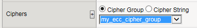 Cipher StringType a cipher string in the box if you want to manually specify a cipher string instead of selecting a cipher group. For security and performance reasons, consider following these recommendations:
- Always append ciphers to theDEFAULTcipher string.
- Type a cipher string that includes the ECC key type, because its shorter length speeds up encryption and decryption while still offering virtually the same level of security.
- Disable ADH ciphers but also include the keywordHIGH. To do this, just include both!ADHand:HIGHin your cipher string.
- For AES, DES, and RC4 encryption types, make sure you specify the DHE key exchange method. DHE usesForward Privacy, which creates a key that it throws away after each session so that the same session key never gets used twice. When you use DHE, make sure that the SSL private key isn't being shared with a monitoring system or a security device like an intrusion detection or prevention system. Also, diagnostic tools likessldumpwon't work when you're using Forward Secrecy.
- Disable EXPORT ciphers by including!EXPORTin the cipher string.
- If you can live with removing support for the SSLv3 protocol version, do it. This protocol version is not secure. Simply include:!SSLv3in any cipher string you type.
Here's an example of theCipherssetting where we have opted to manually type the cipher stringDEFAULT:ECDHE-RSA-AES-128-GCM-SHA256:!ADH:!EXPORT:HIGH: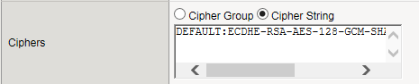
- For theCipherssetting, clickCipher Groupand from the list, select a custom cipher group.This shows a custom cipher group selected for theCipherssetting:
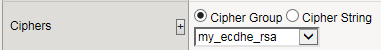
- For theCipherssetting, clickCipher Groupand from the list, select a cipher group.
- To specify DHE ciphers:
- From theConfigurationlist, selectAdvanced.
- For theCipherssetting, clickCipher Stringand typeDHE:DHE_DSS.
- To specify ECDHE ciphers:
- From theConfigurationlist, selectAdvanced.
- In theCiphersfield, typeECDHE.
- Configure all profile settings as needed.
- ClickFinished.
- From thePersistence Typelist, selectSSL.
- Configure settings as needed.
- From theGeneral Propertieslist, selectAdvanced.
- In theNamefield, type a unique name for the OCSP stapling profile.
- In theProxy Server Pool/DNS Resolverfield, select the proxy server pool/DNS resolver used for fetching the OCSP response.
- For theUse Proxy Servercheck box, select one of the following options:OptionDescriptionSelectIf you want the BIG-IP system to use theProxy Server Pool. Use when there are one or more servers that can proxy an HTTP request to an external server and fetch the response.Clear (default)If you want to use theDNS Resolver. Use when the OCSP responder can be reached on one of the BIG-IP interfaces.
- In theTrusted Certificate Authoritiesfield, select the name of the file containing a trusted Certificate Authority (CA) certificate used to sign the responder's certificate.
- In theTrusted Respondersfield, select the name of a certificate to use to verify the response from the OCSP responder.
- In theResponder URLfield, type the name of a URL that will override the OCSP responder URL obtained from the certificate's AIA extension. This must be an HTTP or HTTPS-based URL.
- In theSigner Certificatefield, select a certificate corresponding to the key used for signing the OCSP request.
- In theSigner Keyfield, select a key to use to sign an OCSP request.
- In theSigner Key Passphrasefield, type the passphrase of the key used to sign an OCSP request.
- In theSign Hashfield, select the hash algorithm used to sign an OCSP request. The default isSHA256.This is not the algorithm used in the certificate itself. It is what the OCSP responder will use when validating the request.
- In theTimeoutfield, type a time interval for the BIG-IP system to wait before dropping the connection to the OCSP responder.
- In theClock Skewfield, type a value for the maximum tolerable absolute difference between the clocks of the responder and the BIG-IP system.
- In theStatus Agefield, type a value for the maximum allowed lag time in the OCSP response that the BIG-IP system accepts. If you type0, the validation is skipped. The default value is86400.
- In theCache Timeoutfield, select a value that specifies the lifetime of the OCSP response. The default isIndefinite, indicating that the response validity period takes precedence.
- In theCache Error Timeoutfield, type a value for how long a BIG-IP system will cache an error response.
- In theOptionsfield, if necessary, select theStrict Responder Certificate Checkingcheck box for the system to check the responder's certificate for the OCSP signing extension.
- ClickCreate.The New SIP Profile screen opens.
- Select theSIP Firewallcheck box.When enabled, the SIP Security settings configured in the protection profile apply to the protected object that use this profile.
- If you want to enable optional subscriber ID logging:
- Select theNetwork Address Translationcheck box.
- Then in the Network Address Translation area, select theLog Subscriber IDcheck box.
- ClickNetwork Firewall.
- In the Logging Profile Properties area, select theNetwork Firewallcheck box.
- Select theNetwork Firewallcheck box.
- On the Main tab, click .The MQTT list screen opens.
- ClickCreate.The New MQTT Session profile screen opens.
- In theNamefield, type a unique name for the MQTT session profile.
- From theParent Profilelist, select a profile from which the new profile inherits properties.
- From theParent Profile,Client ID Prefix, andKeepalive Intervallists, retain the default settings.
- For theKeepalive Intervalsetting, retain the default, or type a value for theMQTT CONNECTmessage on the server-side connection.The default is60seconds.
- ClickTransport Config.The Transport Config list screen opens.
- ClickPeers.The Peers list screen opens.
- ClickStatic Routes.The Static Routes list screen opens.
- On the menu bar, clickRouter Profiles.The Router Profiles list screen opens.
- ClickCreate.The New Transport Config screen opens.
- ClickCreate.The New Peer screen opens.
- ClickCreate.The New Route screen opens.
- ClickCreate.The New MQTT Router Profile screen opens.
- In theNamefield, type a unique name for the Transport Config profile.
- In theNamefield, type a unique name for the Peer profile.
- In theNamefield, type a unique name for the Route profile.
- In theNamefield, type a unique name for the Router profile.
- For theProfilessetting, select the profile(s) you want from theAvailablelist, and move it to theSelectedfield.
- In the Settings area, for theClient ID Prefixfield, type a prefix to add to theclient-idfor the server-side connection.
- For theiRulessetting, select the name of the server-side iRule from theAvailablelist, and move it to theSelectedlist.
- If you want to use peered client-side and server-side connections, select thePeered Session Modecheck box.The default is not to use peered connection (the checkbox is cleared); the BIG-IP system uses the MQTT message routing.
- In theProxy Topic Prefixfield, type a prefix to add to the MQTT topics sent on the server-side connection.
- From theClient Will Handling Modelist:
- To disable forwarding of the client will message, selectIgnore.
- To control thewillaction for the ungraceful shutdown of the client-side connection, retain the default.
The default isSend-Local-Copy. - From theServer Will Handling Modelist:
- To exclude the server side connection, selectIgnore.
- To control thewillaction for the ungraceful shutdown of the server-side connection, retain the default.
The default isCopy-From-Client. - Retain the default settings for the remaining settings in the Configuration area.
- From thePoollist, select the name of the pool you created previously.
- From theTransport Configlist, select the name of the Transport Config you created previously.
- From theVirtual Serverlist, select the name of the virtual server you created previously.
- From thePeerlist, select the name of a peer you created previously.
- From theStatic Routelist, select the name of a static route you created previously.
- ClickFinished.The screen refreshes, and you see the new Transport Config profile in the Transport Config list.
- ClickFinished.The screen refreshes, and you see the new MQTT session profile in the MQTT list.
- ClickFinished.The screen refreshes, and you see the new Peer profile in the Peers list.
- ClickFinished.The screen refreshes, and you see the new Route profile in the Static Routes list.
- ClickFinished.The screen refreshes, and you see the new Route profile in the Static Routes list.


