Updated Date: 07/07/2026
Using CGNAT Translation Modes
NAPT mode provides standard address and port translation allowing multiple clients in a private network to access remote networks using the single IP address assigned to their router. For outbound packets, NAPT translates the source IP address and source transport identifier. For inbound packets, NAPT translates the destination IP address, the destination transport identifier, and the IP and transport header checksums. This mode is beneficial for remote access users.
-
NAPT log examples
The following examples describe typical NAPT log messages -
NAPT log examples with timestamp
The following examples describe typical NAPT log messages with timestamp.
The following examples describe typical NAPT log messages
Mar 27 11:17:39 10.10.10.200 lsn_event="LSN_ADD",cli="10.10.10.1: 33950",nat="5.5.5.1:10000"
Mar 27 11:17:39 10.10.10.200 "LSN_ADD""10.10.10.1: 33950""5.5.5.1:10000"
Mar 27 11:23:17 localhost info tmm[32683]: "LSN_ADD""10.10.10.1:33950""5.5.5.1:10000"
Mar 27 11:17:39 10.10.10.200 lsn_event="LSN_DELETE",cli="10.10.10.1: 33950",nat="5.5.5.1:10000"
Mar 27 11:17:39 10.10.10.200 "LSN_DELETE""10.10.10.1: 33950""5.5.5.1:10000"
Mar 27 11:23:17 localhost info tmm[32683]: "LSN_DELETE""10.10.10.1:33950""5.5.5.1:10000"Mar 28 08:34:12 10.10.21.200 lsn_event="LSN_ADD",cli="10.10.10.1%11: 59187",nat="5.5.5.1%22:10000"
Mar 28 08:34:12 10.10.21.200 "LSN_ADD""10.10.10.1%11: 59187""5.5.5.1%22:10000"
Mar 28 08:34:12 10.10.21.200 lsn_event="LSN_DELETE",cli="10.10.10.1%11: 59187",nat="5.5.5.1%22:10000"
Mar 28 08:34:12 10.10.21.200 "LSN_DELETE""10.10.10.1%11: 59187""5.5.5.1%22:10000"Mar 27 11:18:20 10.10.10.200 lsn_event="LSN_ADD",cli="2701: 1:12:123:1234:432:43:100.39900",nat="5.5.5.1:10000"
Mar 27 11:18:20 10.10.10.200 "LSN_ADD""2701: 1:12:123:1234:432:43:100.39900""5.5.5.1:10000"
Mar 27 11:23:57 localhost info tmm[32683]: "LSN_ADD""2701:1:12:123:1234:432:43:100.39900""5.5.5.1:10000"
Mar 27 11:18:23 10.10.10.200 lsn_event="LSN_DELETE",cli="2701: 1:12:123:1234:432:43:100.39900",nat="5.5.5.1:10000"
Mar 27 11:18:23 10.10.10.200 "LSN_DELETE""2701: 1:12:123:1234:432:43:100.39900""5.5.5.1:10000"
Mar 27 11:24:00 localhost info tmm[32683]: "LSN_DELETE""2701:1:12:123:1234:432:43:100.39900""5.5.5.1:10000"Mar 28 14:50:56 10.10.21.200 lsn_event="LSN_ADD",cli="2701: 1:12:123:1234:432:43:100%11.45000",nat="5.5.5.1%22:10000"
Mar 28 14:50:56 10.10.21.200 "LSN_ADD""2701: 1:12:123:1234:432:43:100%11.45000""5.5.5.1%22:10000"
Mar 28 14:50:56 10.10.21.200 lsn_event="LSN_DELETE",cli="2701: 1:12:123:1234:432:43:100%11.45000",nat="5.5.5.1%22:10000"
Mar 28 14:50:56 10.10.21.200 "LSN_DELETE""2701: 1:12:123:1234:432:43:100%11.45000""5.5.5.1%22:10000"Mar 27 11:19:14 10.10.10.200 lsn_event="LSN_ADD",cli="10.10.31.4: 52240",nat="5.5.5.1:10000",dslite="2701::200"
Mar 27 11:19:14 10.10.10.200 "LSN_ADD""10.10.31.4: 52240""5.5.5.1:10000""2701::200"
Mar 27 11:24:52 localhost info tmm[32682]: "LSN_ADD""10.10.31.4:52240""5.5.5.1:10000""2701::200"
Mar 27 11:19:18 10.10.10.200 lsn_event="LSN_DELETE",cli="10.10.31.4: 52240",nat="5.5.5.1:10000",dslite="2701::200"
Mar 27 11:19:18 10.10.10.200 "LSN_DELETE""10.10.31.4: 52240""5.5.5.1:10000""2701::200"
Mar 27 11:24:55 localhost info tmm[32682]: "LSN_DELETE""10.10.31.4:52240""5.5.5.1:10000""2701::200"Mar 28 15:03:40 10.10.21.200 lsn_event="LSN_ADD",cli="10.10.31.4%11: 51942",nat="5.5.5.1%22:10000",dslite="2701::200%11"
Mar 28 15:03:40 10.10.21.200 "LSN_ADD""10.10.31.4%11: 51942""5.5.5.1%22:10000""2701::200%11"
Mar 28 15:03:40 10.10.21.200 lsn_event="LSN_DELETE",cli="10.10.31.4%11: 51942",nat="5.5.5.1%22:10000",dslite="2701::200%11"
Mar 28 15:03:40 10.10.21.200 "LSN_DELETE""10.10.31.4%11: 51942""5.5.5.1%22:10000""2701::200%11"The following examples describe typical NAPT log messages with timestamp.
"LSN_ADD""10.10.10.15:51326""TCP""5.5.5.0:80""1436465636143"
"LSN_DELETE""10.10.10.15:51326""TCP""5.5.5.0:80""1436465636143""4"
"LSN_ADD""10.10.10.15:51326""UDP""5.5.5.0:514""1436465636143"
"LSN_DELETE""10.10.10.15:51326""UDP""5.5.5.0:514""1436465636143""4"
"LSN_ADD""10.10.10.15:51326""ICMP""5.5.5.0:0""1436465636143"
"LSN_DELETE""10.10.10.15:51326""ICMP""5.5.5.0:0""1436465636143""4"ip_protocol="TCP",lsn_event="LSN_ADD",start="1436465636143", cli="10.10.10.15:51326",nat="5.5.5.0:80"
ip_protocol="TCP",lsn_event="LSN_DELETE",start="1436465636143", cli="10.10.10.15:51326",nat="5.5.5.0:80",duration="4"
ip_protocol="UDP",lsn_event="LSN_ADD",start="1436465636143", cli="10.10.10.15:51326",nat="5.5.5.0:514"
ip_protocol="UDP",lsn_event="LSN_DELETE",start="1436465636143", cli="10.10.10.15:51326",nat="5.5.5.0:514",duration="4"
ip_protocol="ICMP",lsn_event="LSN_ADD",start="1436465636143", cli="10.10.10.15:51326",nat="5.5.5.0:0"
ip_protocol="ICMP",lsn_event="LSN_DELETE",start="1436465636143", cli="10.10.10.15:51326",nat="5.5.5.0:0",duration="4"<134>Jul 09 11:13:56 victoria-5 tmm[11075]: "LSN_ADD""10.10.10.15:51326""TCP""4.4.0.0:80""1436465636143"
<134>Jul 09 11:13:56 victoria-5 tmm[11075]: "LSN_DELETE""10.10.10.15:51326""TCP""4.4.0.0:80""1436465636143""4"
<134>Jul 09 11:13:56 victoria-5 tmm[11075]: "LSN_ADD""10.10.10.15:51326""UDP""4.4.0.0:514""1436465636143"
<134>Jul 09 11:13:56 victoria-5 tmm[11075]: "LSN_DELETE""10.10.10.15:51326""UDP""4.4.0.0:514""1436465636143""4"
<134>Jul 09 11:13:56 victoria-5 tmm[11075]: "LSN_ADD""10.10.10.15:51326""ICMP""4.4.0.0:0""1436465636143"
<134>Jul 09 11:13:56 victoria-5 tmm[11075]: "LSN_DELETE""10.10.10.15:51326""ICMP""4.4.0.0:0""1436465636143""4"'Jul 9 11:13:56 slot3/victoria-5 info tmm[11075]: "LSN_ADD""10.10.10.15:51326""TCP""4.4.0.0:80""1436465636143"'
'Jul 9 11:13:56 slot3/victoria-5 info tmm[11075]: "LSN_DELETE""10.10.10.15:51326""TCP""4.4.0.0:80""1436465636143""4"
'Jul 9 11:13:56 slot3/victoria-5 info tmm[11075]: "LSN_ADD""10.10.10.15:51326""UDP""4.4.0.0:514""1436465636143"'
'Jul 9 11:13:56 slot3/victoria-5 info tmm[11075]: "LSN_DELETE""10.10.10.15:51326""UDP""4.4.0.0:514""1436465636143""4"
'Jul 9 11:13:56 slot3/victoria-5 info tmm[11075]: "LSN_ADD""10.10.10.15:51326""ICMP""4.4.0.0:0""1436465636143"'
'Jul 9 11:13:56 slot3/victoria-5 info tmm[11075]: "LSN_DELETE""10.10.10.15:51326""ICMP""4.4.0.0:0""1436465636143""4"- The CGNAT module must be provisioned before LSN pools can be configured.
- Before associating a LSN pool with a log publisher, ensure that at least one log publisher exists on the BIG-IP system.
Large Scale NAT (LSN) pools are used by the CGNAT module to allow efficient configuration of translation prefixes and parameters.
-
On the Main tab, click Carrier Grade NAT > LSN Pools.
The LSN Pool List screen opens.
-
Click Create.
-
In the Name field, type a unique name.
-
In the Description field, type a description.
-
Select NAPT for the pool’s translation Mode.
-
Click Finished.
Your NAPT LSN pool is now ready and you can continue to configure your CGNAT.
VLANs represent a logical collection of hosts that can share network resources, regardless of their physical location on the network. You create a VLAN to associate physical interfaces with that VLAN.
-
On the Main tab, click Network > VLANs.
The VLAN List screen opens.
-
Click Create.
The New VLAN screen opens.
-
In the Name field, type a unique name for the VLAN.
-
In the Tag field, type a numeric tag, between 1-4094, for the VLAN, or leave the field blank if you want the BIG-IP system to automatically assign a VLAN tag.
The VLAN tag identifies the traffic from hosts in the associated VLAN.
-
For the Interfaces setting:
-
From the Interface list, select an interface number or trunk name.
-
From the Tagging list, select Tagged or Untagged.
Select Tagged when you want traffic for that interface to be tagged with a VLAN ID.
-
If you specified a numeric value for the Customer Tag setting and from the Tagging list you selected Tagged, then from the Tag Mode list, select a value.
-
Click Add.
-
Repeat these steps for each interface or trunk that you want to assign to the VLAN.
-
-
From the Configuration list, select Advanced.
-
If you want the system to verify that the return route to an initial packet is the same VLAN from which the packet originated, select the Source Check check box.
-
In the MTU field, retain the default number of bytes (1500).
-
If you want to base redundant-system failover on VLAN-related events, select the Fail-safe check box.
-
From the Auto Last Hop list, select a value.
-
From the CMP Hash list, select Source if this VLAN is the subscriber side or Destination Address if this VLAN is the Internet side.
-
To enable the DAG Round Robin setting, select the check box.
-
For the Hardware SYN Cookie setting, select or clear the check box.
When you enable this setting, the BIG-IP system triggers hardware SYN cookie protection for this VLAN.
Enabling this setting causes additional settings to appear. These settings appear on specific BIG-IP platforms only.
-
For the Syncache Threshold setting, retain the default value or change it to suit your needs.
The Syncache Threshold value represents the number of outstanding SYN flood packets on the VLAN that will trigger the hardware SYN cookie protection feature.
When the Hardware SYN Cookie setting is enabled, the BIG-IP system triggers SYN cookie protection in either of these cases, whichever occurs first:
- The number of TCP half-open connections defined in the LTM setting Global SYN Check Threshold is reached.
- The number of SYN flood packets defined in this Syncache Threshold setting is reached.
-
For the SYN Flood Rate Limit setting, retain the default value or change it to suit your needs.
The SYN Flood Rate Limit value represents the maximum number of SYN flood packets per second received on this VLAN before the BIG-IP system triggers hardware SYN cookie protection for the VLAN.
-
Click Finished.
The screen refreshes, and displays the new VLAN in the list.
You now have one of two VLANs for your deterministic or PBA NAT. Repeat these steps to create a second VLAN to act as the destination if the first VLAN is the source or vice versa.
Virtual servers are matched based on source (client) addresses. Define a NAT64 virtual server that references the CGNAT profile and the LSN pool.
-
On the Main tab, click Carrier Grade NAT > Virtual Servers.
The Virtual Server List screen opens.
-
Click Create.
The New Virtual Server screen opens.
-
In the Name field, type a unique name for the virtual server.
-
From the Type list, select Performance (Layer 4).
-
In the Destination Address/Mask field, type the IPv6 address in CIDR format.
The supported format is address/prefix, where the prefix length is in bits. For example, an IPv6 address/prefix is
64:ff9b::/64or2001:ed8:77b5:2::/64. -
In the Service Port field, type
*or select * All Ports from the list. -
From the Configuration list, select Advanced.
-
From the Protocol list, select * All Protocols.
-
For the LSN Pool setting, select the pool that this server will draw on for translation addresses.
-
For the Address Translation setting, select the Enabled check box to enable address translation.
-
For the Port Translation setting, clear the Enabled check box.
-
For the NAT64 setting, select the Enabled check box.
-
In the Resources area of the screen, for the iRules setting, select the name of the iRule that you want to assign and using the Move button, move the name from the Available list to the Enabled list.
-
Click Finished.
The custom CGNAT NAT64 virtual server now appears in the CGNAT Virtual Servers list.
Port block allocation (PBA) mode is a translation mode option that reduces CGNAT logging, by logging only the allocation and release of each block of ports. When a subscriber first establishes a network connection, the BIG-IP® system reserves a block of ports on a single IP address for that subscriber. The system releases the block when no more connections are using it. This reduces the logging overhead because the CGNAT logs only the allocation and release of each block of ports.
Note: When a subscriber first connects, the PBA translation mode applies client port block limits, which the subscriber uses as long as it has addresses allocated. For each subscriber, PBA mode compares the subscriber’s allocated number of port blocks to the port block limit for the currently connected pool. If the allocated number of port blocks exceeds the port block limit, then the connection is denied. For example, if a subscriber’s allocated number of port blocks is 2, and the port block limit for the currently connected pool is 1, then the connection is denied.
-
PBA log examples
Following are some examples of the elements that comprise a typical Port Block Allocation (PBA) mode log entry.
Port Block Allocation (PBA) mode provides you with the ability to log only the allocation and release of port blocks for a subscriber, instead of separately logging each network address translation (NAT) session as a separate translation event, as with network address and port translation (NAPT), thus reducing the number of log entries while maintaining legal mapping and reverse mapping requirements.
Configuration restrictions for PBA mode include these constraints.
- PBA mode is compatible only with SP-DAG. If a VLAN is used that is not compatible with SP-DAG, then NAPT mode becomes active and an error is logged.
- You can configure overlapping LSN prefixes only between pools of the same type. LSN prefixes are not overlapping when the port ranges for the prefixes do not overlap.
- The system allocates one primary port block for each subscriber, with the allocation of an additional overflow port block, as necessary.
- The Client Connection Limit (CCL) value constrains the number of subscriber connections, preventing any one subscriber from using an excessive number of connections.
- PBA mode is available with NAT44, NAT64, and DS-Lite.
PBA mode manages connections by means of the following characteristics.
- Port allocation within an active port block occurs until all available ports become allocated, or until the Block Lifetime limit is exceeded.
- The Block Idle Timeout value specifies the period between when the last connection using a port block is freed and when the port block can be reused.
Important: A zombie port block, which is a port block that has reached the Block Lifetime limit but cannot be released due to active connections, is released when all active connections become inactive, or when the Zombie Timeout value is reached.
When you use PBA mode, a log entry is sent when a block of ports is allocated for a subscriber, and again when a block of ports is released. Log entries include the range of ports (that is, the port block) from the start port through the end port. Several logging destinations are available for PBA mode, including Syslog, Splunk, and IPFIX.
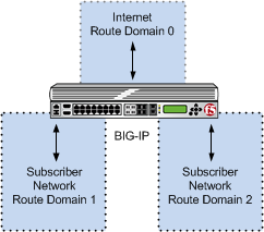
Port block allocation (PBA) mode can be used with route domains to configure multiple subscriber networks in separate route domains. You can also partition subscriber networks and the Internet by using route domains.
A route domain that is used for the translation entry is not the subscriber route domain. The subscriber route domain is, instead, applied to the egress interface.
In the following configuration, multiple subscribers can connect to servers in Internet route domain 0. The BIG-IP system allocates, to each subscriber, available port blocks from Internet route domain 0 that include unique addresses and ports.
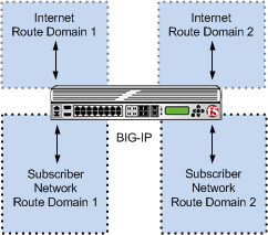
In the next configuration, multiple subscribers can connect to servers in respective Internet route domains. The BIG-IP system allocates available port blocks from the respective Internet route domain to the corresponding subscriber. Allocated port blocks can differ only by route domain, and use identical address and port ranges; consequently, for this configuration, a service provider must provide a means to distinguish the connections of different route domains, as necessary.
Following are some examples of the elements that comprise a typical Port Block Allocation (PBA) mode log entry.
PBA log messages include several elements of interest. The following examples show typical log messages, and the table describes common information types.
Jul 23 09:33:42 www.siterequest.com "LSN_PB_ALLOCATED""10.10.10.1""5.5.5.9: 5555-6666"
Jul 23 09:33:42 www.siterequest.com "LSN_PB_RELEASED""10.10.10.1""5.5.5.9: 5555-6666"Jul 23 09:33:42 www.siterequest.com "LSN_PB_ALLOCATED""10.10.10.1%55""5.5.5.9%22: 5555-6666"
Jul 23 09:33:42 www.siterequest.com "LSN_PB_RELEASED""10.10.10.1%55""5.5.5.9%22: 5555-6666"Jul 23 10:46:31 www.siterequest.com "LSN_PB_ALLOCATED""2701: :200""5.5.5.9:5555-6666"
Jul 23 10:46:31 www.siterequest.com "LSN_PB_RELEASED""2701: :200""5.5.5.9:5555-6666"Jul 23 09:36:33 www.siterequest.com "LSN_PB_ALLOCATED""2701: :200%11""5.5.5.9%22:5555-6666"
Jul 23 09:36:33 www.siterequest.com "LSN_PB_RELEASED""2701: :200%11""5.5.5.9%22:5555-6666"Jul 23 09:36:33 www.siterequest.com "LSN_PB_ALLOCATED""2701: :200""5.5.5.9:5555-6666"
Jul 23 09:36:33 www.siterequest.com "LSN_PB_RELEASED""2701: :200"5.5.5.9:5555-6666"Jul 23 09:36:33 www.siterequest.com "LSN_PB_ALLOCATED""2701: :200%33""5.5.5.9%22:5555-6666"
Jul 23 09:36:33 www.siterequest.com "LSN_PB_RELEASED""2701: :200%33""5.5.5.9%22:5555-6666"Jul 23 10:56:13 www.siterequest.com lsn_event="LSN_PB_ALLOCATED",lsn_client="10.10.10.1",lsn_pb="5.5.5.9: 5555-6666"
Jul 23 10:56:13 www.siterequest.com lsn_event="LSN_PB_RELEASED",lsn_client="10.10.10.1",lsn_pb="5.5.5.9: 5555-6666"Jul 23 10:56:13 www.siterequest.com lsn_event="LSN_PB_ALLOCATED",lsn_client="10.10.10.1%55",lsn_pb="5.5.5.9%22: 5555-6666"
Jul 23 10:56:13 www.siterequest.com lsn_event="LSN_PB_RELEASED",lsn_client="10.10.10.1%55",lsn_pb="5.5.5.9%22: 5555-6666"Jul 23 10:57:08 www.siterequest.com lsn_event="LSN_PB_ALLOCATED",lsn_dslite_client="2701: :200",lsn_pb="5.5.5.9:5555-6666"
Jul 23 10:57:08 www.siterequest.com lsn_event="LSN_PB_RELEASED",lsn_dslite_client="2701: :200",lsn_pb="5.5.5.9:5555-6666"Jul 23 10:57:08 www.siterequest.com lsn_event="LSN_PB_ALLOCATED",lsn_dslite_client="2701: :200%11",lsn_pb="5.5.5.9%22:5555-6666"
Jul 23 10:57:08 www.siterequest.com lsn_event="LSN_PB_RELEASED",lsn_dslite_client="2701: :200%11",lsn_pb="5.5.5.9%22:5555-6666"Jul 23 10:57:08 www.siterequest.com lsn_event="LSN_PB_ALLOCATED",lsn_client="2701: :200",lsn_pb="5.5.5.9:5555-6666"
Jul 23 10:57:08 www.siterequest.com lsn_event="LSN_PB_RELEASED",lsn_client="2701: :200",lsn_pb="5.5.5.9:5555-6666"Jul 23 10:57:08 www.siterequest.com lsn_event="LSN_PB_ALLOCATED",lsn_client="2701: :200%33",lsn_pb="5.5.5.9%22:5555-6666"
Jul 23 10:57:08 www.siterequest.com lsn_event="LSN_PB_RELEASED",lsn_client="2701: :200%33",lsn_pb="5.5.5.9%22:5555-6666"|
Information Type |
Example Value |
Description |
|---|---|---|
|
Timestamp |
|
Specifies the time and date that the system logged the event message. |
|
Domain name |
|
Specifies the domain name of the client. |
|
LSN event |
|
Specifies the allocation or release of the port block. Note: |
|
Client address |
|
Specifies the address of the client. |
|
Port block address |
|
Specifies the address of the port block. |
|
Port range start |
|
Specifies the start of the port range. |
|
Port range end |
|
Specifies the end of the port range. |
- The CGNAT module must be provisioned before LSN pools can be configured.
- Before associating a LSN pool with a log publisher, ensure that at least one log publisher exists on the BIG-IP system.
You configure Large Scale NAT (LSN) pools for the CGNAT module to use in allowing efficient configuration of translation prefixes and parameters.
-
On the Main tab, click Carrier Grade NAT > LSN Pools.
The LSN Pool List screen opens.
-
Click Create.
-
In the Name field, type a unique name.
-
In the Description field, type a description.
-
For the Mode setting, select PBA for the pool’s translation.
Note that PBA mode for DS-lite is same as for NAT44, except that all clients behind the DS-Lite tunnel are managed as one subscriber. Port block limits are in accordance with each DS-lite tunnel.
-
For the Port Block Allocation setting, specify your preferred PBA configuration.
-
In the Block Size field, type the number of ports designated for a block.
-
In the Block Lifetime field, type the number of seconds before a port block times out.
Note: If you type a timeout other than
0, you can also specify a Zombie Timeout. A Block Lifetime value that is less than the Persistence Timeout value minimizes the number of zombie port blocks. The default value of0specifies no lifetime limit and indefinite use of the port block. -
In the Block Idle Timeout field, enter the timeout (in seconds) for after the port block becomes idle.
Note: Typically, you want to use a Block Idle Timeout value less than the Persistence Timeout value, to minimize the number of zombie port blocks.
-
In the Client Block Limit field, type the number of blocks that can be assigned to a single subscriber IP address.
-
In the Zombie Timeout field, type the number of seconds before port block times out.
A zombie port block is a timed out port block with one or more active connections. The default value of
0specifies no timeout and an indefinite zombie state for the port block, as long as connections remain active. A value other than0specifies a timeout expiration, upon which existing connections are terminated, and the port block is released and returned to the pool.
-
-
In the Configuration area, for the Member List setting, type an address and a prefix length in the Address/Prefix Length field, and click Add.
-
Click Finished.
Your PBA LSN pool is now ready, and you can continue to configure your CGNAT.
VLANs represent a logical collection of hosts that can share network resources, regardless of their physical location on the network. You create a VLAN to associate physical interfaces with that VLAN.
-
On the Main tab, click Network > VLANs.
The VLAN List screen opens.
-
Click Create.
The New VLAN screen opens.
-
In the Name field, type a unique name for the VLAN.
-
In the Tag field, type a numeric tag, between 1-4094, for the VLAN, or leave the field blank if you want the BIG-IP system to automatically assign a VLAN tag.
The VLAN tag identifies the traffic from hosts in the associated VLAN.
-
For the Interfaces setting:
-
From the Interface list, select an interface number or trunk name.
-
From the Tagging list, select Tagged or Untagged.
Select Tagged when you want traffic for that interface to be tagged with a VLAN ID.
-
If you specified a numeric value for the Customer Tag setting and from the Tagging list you selected Tagged, then from the Tag Mode list, select a value.
-
Click Add.
-
Repeat these steps for each interface or trunk that you want to assign to the VLAN.
-
-
From the Configuration list, select Advanced.
-
If you want the system to verify that the return route to an initial packet is the same VLAN from which the packet originated, select the Source Check check box.
-
In the MTU field, retain the default number of bytes (1500).
-
If you want to base redundant-system failover on VLAN-related events, select the Fail-safe check box.
-
From the Auto Last Hop list, select a value.
-
From the CMP Hash list, select Source if this VLAN is the subscriber side or Destination Address if this VLAN is the Internet side.
-
To enable the DAG Round Robin setting, select the check box.
-
For the Hardware SYN Cookie setting, select or clear the check box.
When you enable this setting, the BIG-IP system triggers hardware SYN cookie protection for this VLAN.
Enabling this setting causes additional settings to appear. These settings appear on specific BIG-IP platforms only.
-
For the Syncache Threshold setting, retain the default value or change it to suit your needs.
The Syncache Threshold value represents the number of outstanding SYN flood packets on the VLAN that will trigger the hardware SYN cookie protection feature.
When the Hardware SYN Cookie setting is enabled, the BIG-IP system triggers SYN cookie protection in either of these cases, whichever occurs first:
- The number of TCP half-open connections defined in the LTM setting Global SYN Check Threshold is reached.
- The number of SYN flood packets defined in this Syncache Threshold setting is reached.
-
For the SYN Flood Rate Limit setting, retain the default value or change it to suit your needs.
The SYN Flood Rate Limit value represents the maximum number of SYN flood packets per second received on this VLAN before the BIG-IP system triggers hardware SYN cookie protection for the VLAN.
-
Click Finished.
The screen refreshes, and displays the new VLAN in the list.
You now have one of two VLANs for your deterministic or PBA NAT. Repeat these steps to create a second VLAN to act as the destination if the first VLAN is the source or vice versa.
Virtual servers are matched based on source (client) addresses. Define a virtual server that references the CGNAT profile and the LSN pool.
-
On the Main tab, click Carrier Grade NAT > Virtual Servers.
The Virtual Server List screen opens.
-
Click Create.
The New Virtual Server screen opens.
-
In the Name field, type a unique name for the virtual server.
-
From the Type list, select Performance (Layer 4).
-
For a network, in the Destination Address/Mask field, type an IPv4 or IPv6 address in CIDR format to allow all traffic to be translated.
The supported format is address/prefix, where the prefix length is in bits. For example, an IPv4 address/prefix is
0.0.0.0/0, and an IPv6 address/prefix is::/0. -
In the Service Port field, type
*or select * All Ports from the list. -
From the VLAN and Tunnel Traffic list, select Enabled on. Then, for the VLANs and Tunnels setting, move the VLAN or VLANs on which you want to allow the virtual servers to share traffic from the Available list to the Selected list.
-
For the LSN Pool setting, select the pool that this server will draw on for translation addresses.
-
In the Resources area of the screen, for the iRules setting, select the name of the iRule that you want to assign and using the Move button, move the name from the Available list to the Enabled list.
-
Click Finished.
The custom CGNAT virtual server now appears in the CGNAT Virtual Servers list.
Deterministic address translation mode provides address translation that eliminates logging of every address mapping, while still allowing internal client address tracking using only an external address and port, and a destination address and port. Reverse mapping allows BIG-IP® CGNAT operators to respond to legal requests revealing the identity of the originator of a specific communication. A typical example is revealing the identity of file sharers or P2P network users accused of copyright theft.
Deterministic mode allows unique identification of internal client address based on:
- External address and port (the address and port visible to the destination server)
- Destination address and port (the service accessed by the client)
- Time
Deterministic mode has these configuration restrictions:
-
Only NAT44 can use deterministic mode.
-
The subscriber (client-side) and Internet (server-side) interfaces (VLANs) must be set either as a source or destination address in the CMP Hashsetting.
-
The complete set of all internal client addresses that will ever communicate through the CGNAT must be entered at configuration time.
Note: This means that all virtual servers referring to an LSN pool through deterministic NAT mode must specify the source attribute with a value other than 0.0.0.0/0 or ::/0 (any/0, any6/0).
-
Use only the most specific address prefixes covering all customer addresses.
-
Members of two or more deterministic LSN pools must not overlap; in other words, every external address used for deterministic mapping must occur in only one LSN pool.
-
Deterministic mode does not support IPFIX.
As an alternative to per-connection logging, deterministic mode maps internal addresses to external addresses algorithmically to calculate the mapping without relying on per-connection logging. Deterministic mode significantly reduces the logging burden while mapping a subscriber’s inside IP address with an outside Internet address and port.
To decipher mapping generated by LSN pools using deterministic mode, you must use the DNAT utility that can be run from the system’s tmsh command prompt.
The CGNAT module must be provisioned before you can configure LSN pools.
Large Scale NAT (LSN) pools are used by the CGNAT module to allow efficient configuration of translation prefixes and parameters.
-
On the Main tab, click Carrier Grade NAT > LSN Pools.
The LSN Pool List screen opens.
-
Click Create.
-
In the Name field, type a unique name.
-
For the Mode setting, select Deterministic for the pool’s translation.
Note that deterministic mode does not support DS-lite tunneling or NAT64.
-
From the Log Publisher list, select the publisher that includes the destinations to which you want to send log messages.
-
In the Configuration area, for the Member List setting, type an address and a prefix length in the Address/Prefix Length field, and click Add.
If your pool uses deterministic mode, ensure that any address ranges you enter as a member do not overlap another member’s prefix address ranges. For example, the address and prefix
10.10.10.0/24overlaps10.10.10.0/23. -
For deterministic mode, the Backup Member List must have at least one member, so type an address in the Address/Prefix Length field and click Add.
-
Click Finished.
Your deterministic LSN pool is now ready, and you can continue to configure your CGNAT.
VLANs represent a logical collection of hosts that can share network resources, regardless of their physical location on the network. You create a VLAN to associate physical interfaces with that VLAN.
-
On the Main tab, click Network > VLANs.
The VLAN List screen opens.
-
Click Create.
The New VLAN screen opens.
-
In the Name field, type a unique name for the VLAN.
-
In the Tag field, type a numeric tag, between 1-4094, for the VLAN, or leave the field blank if you want the BIG-IP system to automatically assign a VLAN tag.
The VLAN tag identifies the traffic from hosts in the associated VLAN.
-
For the Interfaces setting:
-
From the Interface list, select an interface number or trunk name.
-
From the Tagging list, select Tagged or Untagged.
Select Tagged when you want traffic for that interface to be tagged with a VLAN ID.
-
If you specified a numeric value for the Customer Tag setting and from the Tagging list you selected Tagged, then from the Tag Mode list, select a value.
-
Click Add.
-
Repeat these steps for each interface or trunk that you want to assign to the VLAN.
-
-
From the Configuration list, select Advanced.
-
If you want the system to verify that the return route to an initial packet is the same VLAN from which the packet originated, select the Source Check check box.
-
In the MTU field, retain the default number of bytes (1500).
-
If you want to base redundant-system failover on VLAN-related events, select the Fail-safe check box.
-
From the Auto Last Hop list, select a value.
-
From the CMP Hash list, select Source if this VLAN is the subscriber side or Destination Address if this VLAN is the Internet side.
-
To enable the DAG Round Robin setting, select the check box.
-
For the Hardware SYN Cookie setting, select or clear the check box.
When you enable this setting, the BIG-IP system triggers hardware SYN cookie protection for this VLAN.
Enabling this setting causes additional settings to appear. These settings appear on specific BIG-IP platforms only.
-
For the Syncache Threshold setting, retain the default value or change it to suit your needs.
The Syncache Threshold value represents the number of outstanding SYN flood packets on the VLAN that will trigger the hardware SYN cookie protection feature.
When the Hardware SYN Cookie setting is enabled, the BIG-IP system triggers SYN cookie protection in either of these cases, whichever occurs first:
- The number of TCP half-open connections defined in the LTM setting Global SYN Check Threshold is reached.
- The number of SYN flood packets defined in this Syncache Threshold setting is reached.
-
For the SYN Flood Rate Limit setting, retain the default value or change it to suit your needs.
The SYN Flood Rate Limit value represents the maximum number of SYN flood packets per second received on this VLAN before the BIG-IP system triggers hardware SYN cookie protection for the VLAN.
-
Click Finished.
The screen refreshes, and displays the new VLAN in the list.
You now have one of two VLANs for your deterministic or PBA NAT. Repeat these steps to create a second VLAN to act as the destination if the first VLAN is the source or vice versa.
Virtual servers are matched based on source (client) addresses. Define a virtual server that references the CGNAT profile and the LSN pool.
-
On the Main tab, click Carrier Grade NAT > Virtual Servers.
The Virtual Server List screen opens.
-
Click Create.
The New Virtual Server screen opens.
-
In the Name field, type a unique name for the virtual server.
-
From the Type list, select Performance (Layer 4).
-
For a network, in the Destination Address/Mask field, type an IPv4 or IPv6 address in CIDR format to allow all traffic to be translated.
The supported format is address/prefix, where the prefix length is in bits. For example, an IPv4 address/prefix is
0.0.0.0/0, and an IPv6 address/prefix is::/0. -
In the Service Port field, type
*or select * All Ports from the list. -
From the VLAN and Tunnel Traffic list, select Enabled on. Then, for the VLANs and Tunnels setting, move the VLAN or VLANs on which you want to allow the virtual servers to share traffic from the Available list to the Selected list.
-
For the LSN Pool setting, select the pool that this server will draw on for translation addresses.
-
In the Resources area of the screen, for the iRules setting, select the name of the iRule that you want to assign and using the Move button, move the name from the Available list to the Enabled list.
-
Click Finished.
The custom CGNAT virtual server now appears in the CGNAT Virtual Servers list.
BIG-IP® deterministic NAT (DNAT) mode allows conservation of log storage for service providers by mapping subscribers to public translation addresses and ports algorithmically so that very little data needs to be stored in logs. The DNAT utility (dnatutil) is necessary for identifying subscribers through calculation of reverse source address and port mapping of deterministic-mode LSN pools, by using the states stored in the log files.
The DNAT utility can interpret logs from version 11.4.0 and later, correctly reverse mapping subscribers, or forward mapping possible end-points of the subscriber. DNAT, as of version 11.5 of the BIG-IP system, supports multiple log destinations including, LTM, Remote Syslog, and Splunk. The DNAT utility can parse logs from any supported DNAT log destination.
The DNAT utility binary can be run either on the BIG-IP system or on any supported Linux host. The DNAT utility package currently supports CentOS 64 and Ubuntu 64 for deployment on Linux systems to support reverse mappings on archived logs. The package is available from the F5 Downloads site (http://support.f5.com/kb/en-us.html).
-
DNAT utility example commands
This list provides examples of the syntax used in commands fordnatutil. -
Using DNAT utility to look up deterministic NAT mappings on the BIG-IP system
This list provides examples of the syntax used in commands for dnatutil.
| Command | Response |
|---|---|
dnatutil 10.0.0.1 --action forward |
Shows a list of translation address/port pairs that might be used for a subscriber at 10.0.0.1, using the DNAT states contained in /var/log/ltm. |
dnatutil 173.240.102.139:5678 |
Performs a reverse mapping back to the subscriber address for the connection from 173.240.102.139:5678, using the DNAT states contained in /var/log/ltm. |
dnatutil --start_time ’2012-09-27 06:30:00’ --end_time ’2012-09-27 12:10:00’ 173.240.102.139:5678 |
Performs a reverse mapping back to the subscriber address for the connection from 173.240.102.139:5678, but only shows the subscriber addresses that used the translation within the specified time range. |
dnatutil --start_time ’2012-09-27 06:30:00’ --end_time ’2012-09-27 12:10:00’ --file ltmlog-21102013 173.240.102.139:5678 |
Performs a reverse mapping back to the subscriber address for the connection from 173.240.102.139:5678, showing the subscriber addresses that used the translation within the specified time range, and using the DNAT states contained in /var/log/test. |
dnatutil --file /var/log/test |
Shows summary information, using the DNAT states contained in /var/log/test. |
dnatutil --action summary --start_time ’2012-09-27 06:30:00’ --end_time ’2012-09-27 12:10:00’ |
Shows summary information, using the DNAT states within the specified time range. |
dnatutil --action reverse_addr 1.2.3.4 |
Shows a list of possible subscriber addresses for the provided client address. |
| `dnatutil –help | grep DAG_ID` |
The deterministic NAT (DNAT) reverse mapping tool can run independently from the BIG-IP system. Follow these steps to download the dnatutil RPM or Debian file from the F5 Downloads site.
-
Access the F5 Downloads site at
http://downloads.f5.com. -
From the Downloads Overview page, click Find a Download.
The Select a Product Line page displays.
-
Under Product Line, click the BIG-IP software branch BIG-IP v12.x.
-
Select BIG-IP version 12.x from the drop-down menu.
The system selects the most recent version of software, by default.
-
From the Name column, select DNAT-Utility.
A Software Terms and Conditions page appears.
-
Read the End User Software License Agreement (EULA) and either accept the license by clicking I Accept, or cancel the process by clicking Cancel.
If you accept the EULA, the Select a Download page appears with a table detailing the file name, product description, and size of the file. You should see three files:
- dnatutil.rpm
- dnatutil.deb
- readme.txt
-
Select the file you would like to download.
Now that you have downloaded the DNAT utility RPM/Debian package, you can now use dnatutil for forward and reverse mappings.
To discover the subscriber address, you need to have at least the NAT/public address you would like to translate. It is preferable to have the date, time, and NAT/public address, port, and the archived logs with the state information you wish to use.
Deterministic NATs (DNATs) can reduce total log file size but require use of the DNAT utility (dnatutil) to decipher the mapping. With dnatutil, you can calculate forward end-points and reverse client address and port mapping of an LSN pool using deterministic mode based on the state stored in the specified log file.
-
Download the BIG-IP version 11.x RPM or Debian file from the F5 Downloads web site (
https://downloads.f5.com) to a preferred location. -
Using the command line, type
install -Uvh <rpm>to install the RPM file. -
Type
dnatutilwith the date, time, NAT/public address, and port that you want to translate.dnatutil –-file /var/log/messages --start_time "2013-10-02 15:21:12" –-end_time "2013-10-02 15:22:42" 1.1.1.1:1234 -
Press enter.
If the BIG-IP platform is located in a different time zone than the receiving log server, messages might not be correctly interpreted.
TZis an environmental variable that specifies the timezone. If not specified, the local timezone is used.# dnatutil --file ltm 1.1.7.1:1025 From (1365014711): 2013-04-03 18:45:11 GMT Reverse mapping for ::,80 -> 1.1.7.1,1025 Using cmp-hash 'dst-ip' and TMM 1:10.10.10.11The log entry will show the source prefix, destination prefix (public address), and the subscriber IP address for the time range.
You now have the basic details for deciphering deterministic log files using the DNAT utility.
You should know how to navigate in tmsh before using the DNAT utility (dnatutil). For detailed information about navigating in tmsh, see the Traffic Management Shell (tmsh) Reference Guide.
Deterministic NATs can reduce total log file size but require use of the dnatutil (available in tmsh) to decipher the mapping. With the dnatutil, you can calculate forward and reverse source address and port mapping of an LSN pool using deterministic mode based on the state stored in the specified TMM log file.
-
Use an SSH tool to access the BIG-IP system from the command line.
-
At the command line, type:
tmsh.This starts
tmshin interactive shell mode and displays the prompt:(tmos)#. -
Note: If you do not provide a file and you are on a BIG-IP system, it will default to the LTM log.
To show a list of translation address/port pairs used for a subscriber at
10.0.0.1:4321connecting to65.61.115.222:80, using the deterministic NAT states contained in/var/log/ltm, type the command:run util dnat --file /var/log/ltm --client_addr 10.0.0.1 --client_port 4321 --server_addr 65.61.115.222 --action forwardReplace these example addresses with your actual client and server.
This displays a list of the address/port pairs.
-
To calculate a reverse mapping back to the subscriber address for the connection between 173.240.102.139:5678 and 65.61.115.222:80, using the DNAT states contained in
/var/log/ltm.1, type the command:run util dnat --file /var/log/ltm.1 --server_addr 65.61.115.222 --client_addr 173.240.102.139 --client_port 5678 --action reverseThis displays the reverse mapping.
-
For more information about the DNAT utility, type the command:
help util dnatat thetmshprompt.The help file for the DNAT utility is displayed.
You now have the basic details for deciphering deterministic log files using the DNAT utility in tmsh.
Port Control Protocol (PCP) clients can request specific NAT/CGNAT mappings for themselves and/or for third-party devices. This allows the PCP clients to set their own public-side IP addresses (also called translation addresses) in a network that uses CGNAT. In cases where the BIG-IP® system assigns a translation address or port other than the one requested, the client is at least aware of their assigned address or port.
You apply a PCP profile to a Large Scale NAT (LSN) pool of translation addresses. A client that uses the LSN pool can also send PCP requests to the BIG-IP system to request a particular address/port from the pool. RFC 6887 defines PCP.
Someone must license the CGNAT module through System > License, and enable it through System > Resource Provisioning before you can create a PCP profile.
A PCP profile defines limitations for PCP-client requests.
-
On the Main tab, click Carrier Grade NAT > PCP Profiles > +.
The New PCP Profile screen opens.
-
In the Name field, type a unique name.
-
You can accept the defaults in this profile, or you can select the check box next to any setting that you want to change.
The online help describes each field.
-
Click Finished.
Your PCP profile is now ready to be used in one or more LSN pools.
An LSN Pool is a group of addresses and ports to be used as translation addresses by a virtual server’s clients. If one of those clients sends a PCP request (for example, to map the client’s private IP address to a particular translation address), the LSN pool’s PCP profile determines the ranges and limits allowed for the request.
You assign a PCP profile to an LSN pool in the pool’s configuration screen. You also designate the IP address and/or DS-Lite tunnel to which the virtual server’s clients can send their PCP requests.
-
On the Main tab, click Carrier Grade NAT > LSN Pools.
The LSN Pool List screen opens.
-
Click the name of an LSN pool.
-
From the PCP Profile list, select a pre-created PCP profile.
If you have not yet created a customized profile, you can use the default PCP profile pcp.
The other two PCP-related settings become active.
-
Type a self IP address or a DS-Lite tunnel where the virtual server’s clients can send their PCP requests. You can use either field:
- Use the PCP Server IP list to select one of the existing self IP addresses on the system, or
- Use the PCP DS-LITE Tunnel Name - IPv6 list to select an existing DS-Lite tunnel The virtual server’s clients can send PCP requests to the self-IP address or through the DS-Lite tunnel you selected.
After you perform this task, any virtual server with this LSN pool can support PCP. The virtual server’s clients can send PCP MAP requests to the address or tunnel you specified here.
No client can use this PCP configuration unless the LSN pool is assigned to at least one virtual server. Go to Carrier Grade NAT > Virtual Servers > Virtual Server List for a list of servers. Look for the LSN pool’s name in the LSN Pool column. Confirm that at least one virtual server uses this LSN pool.