Updated Date: 07/07/2026
Configuring BIG-IP DNS on a Network with Multiple Route Domains
You can deploy BIG-IP® DNS (formerly GTM) on a network where BIG-IP Local Traffic Manager (LTM) systems are configured with multiple route domains and overlapping IP addresses.
Important: On a BIG-IP® system that includes both Local Traffic Manager (LTM) and Global Traffic Manager™ (now BIG-IP ® DNS), all IP addresses that BIG-IP DNS references (virtual IP addresses, link addresses, and so on) must be associated with route domain 0.
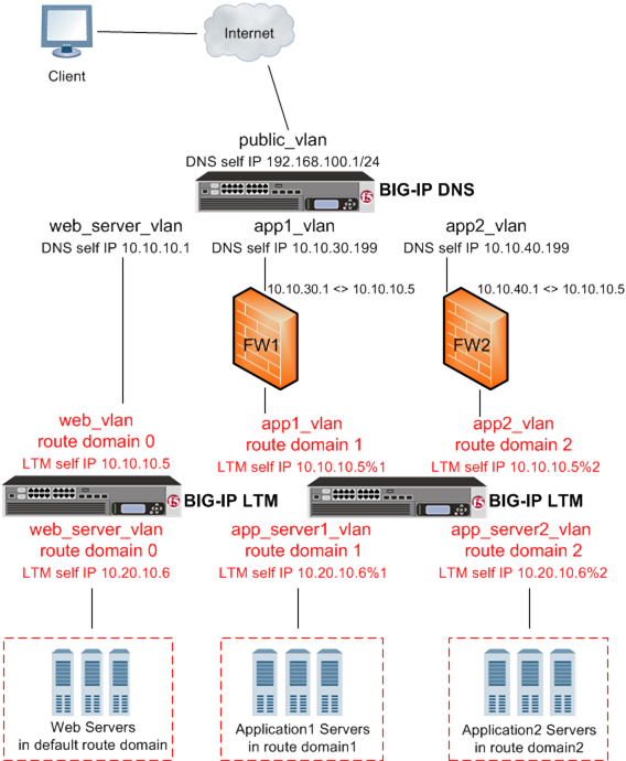
The following figure shows BIG-IP DNS deployed in a network with multiple BIG-IP Local Traffic Manager (LTM) systems, one configured with the default route domain (zero), and one configured with two additional route domains. BIG-IP DNS can monitor the Application1 and Application2 servers that have overlapping IP addresses and reside in different route domains. The firewalls perform the required address translation between the BIG-IP DNS and BIG-IP LTM addresses; you must configure the firewalls to segment traffic and avoid improperly routing packets between route domain 1 and route domain 2.
Before BIG-IP® DNS can gather status and statistics for the virtual servers hosted on BIG-IP LTM systems that are configured with route domains, you must configure the following on each BIG-IP LTM that handles traffic for route domains:
- VLANs through which traffic for your route domains passes
- Route domains that represent each network segment
- Self IP addresses that represent the address spaces of the route domains
Additionally, configure a BIG-IP DNS server object on BIG-IP DNS to represent each LTM system device.
Perform the following tasks to configure BIG-IP DNS to monitor BIG-IP LTM systems with route domains.
Create two VLANs on BIG-IP LTM through which traffic can pass to a route domain.
-
On the Main tab, click Network > VLANs.
The VLAN List screen opens.
-
Click Create.
The New VLAN screen opens.
-
In the Name field, type
external. -
In the Tag field, type a numeric tag, between 1-4094, for the VLAN, or leave the field blank if you want the BIG-IP system to automatically assign a VLAN tag.
The VLAN tag identifies the traffic from hosts in the associated VLAN.
-
If you want to use Q-in-Q (double) tagging, use the Customer Tag setting to perform the following two steps. If you do not see the Customer Tag setting, your hardware platform does not support Q-in-Q tagging and you can skip this step.
-
From the Customer Tag list, select Specify.
-
Type a numeric tag, from 1-4094, for the VLAN.
The customer tag specifies the inner tag of any frame passing through the VLAN.
-
-
For the Interfaces setting:
-
From the Interface list, select an interface number or trunk name.
-
From the Tagging list, select Tagged or Untagged.
Select Tagged when you want traffic for that interface to be tagged with a VLAN ID.
-
If you specified a numeric value for the Customer Tag setting and from the Tagging list you selected Tagged, then from the Tag Mode list, select a value.
-
Click Add.
-
Repeat these steps for each interface or trunk that you want to assign to the VLAN.
-
-
If you want the system to verify that the return route to an initial packet is the same VLAN from which the packet originated, select the Source Check check box.
-
For the Hardware SYN Cookie setting, select or clear the check box.
When you enable this setting, the BIG-IP system triggers hardware SYN cookie protection for this VLAN.
Enabling this setting causes additional settings to appear. These settings appear on specific BIG-IP platforms only.
-
For the Syncache Threshold setting, retain the default value or change it to suit your needs.
The Syncache Threshold value represents the number of outstanding SYN flood packets on the VLAN that will trigger the hardware SYN cookie protection feature.
When the Hardware SYN Cookie setting is enabled, the BIG-IP system triggers SYN cookie protection in either of these cases, whichever occurs first:
- The number of TCP half-open connections defined in the LTM setting Global SYN Check Threshold is reached.
- The number of SYN flood packets defined in this Syncache Threshold setting is reached.
-
For the SYN Flood Rate Limit setting, retain the default value or change it to suit your needs.
The SYN Flood Rate Limit value represents the maximum number of SYN flood packets per second received on this VLAN before the BIG-IP system triggers hardware SYN cookie protection for the VLAN.
-
Click Finished.
The screen refreshes, and displays the new VLAN in the list.
Repeat this procedure, but in Step 3, name the VLAN internal.
Ensure that VLANs exist on BIG-IP LTM, before you create a route domain.
You can create a route domain on a BIG-IP system to segment (isolate) network traffic on your network.
-
On the Main tab, click Network > Route Domains.
The Route Domain List screen opens.
-
Click Create.
The New Route Domain screen opens.
-
In the ID field, type an ID number for the route domain.
This ID must be unique on the BIG-IP system; that is, no other route domain on the system can have this ID.
An example of a route domain ID is
1. -
In the Description field, type a description of the route domain.
For example:
This route domain applies to application traffic for Customer A. -
For the Strict Isolation setting, select the Enabled check box to restrict traffic in this route domain from crossing into another route domain.
-
For the Parent Name setting, retain the default value.
-
For the VLANs setting, move the external and internal VLANs from the Available list, to the Members list.
Configuring this setting ensures that the BIG-IP system immediately associates any self IP addresses pertaining to the selected VLANs with this route domain.
-
Click Finished.
The system displays a list of route domains on the BIG-IP system.
Create additional route domains based on your network configuration.
Ensure that VLANs exist on BIG-IPLTM, before you begin creating a self IP address for a route domain.
Create a self IP address on the BIG-IP system that resides in the address space of the route domain.
-
On the Main tab, click Network > Self IPs.
-
Click Create.
The New Self IP screen opens.
-
In the Name field, type a unique name for the self IP address.
-
In the IP Address field, type an IP address.
This IP address must represent a self IP address in a route domain. Use the format
x.x.x.x%n, wherenis the route domain ID, for example, 10.1.1.1%1.The system accepts IPv4 and IPv6 addresses.
-
In the Netmask field, type the network mask for the specified IP address.
For example, you can type
255.255.255.0. -
From the VLAN/Tunnel list, select the VLAN that you assigned to the route domain that contains this self IP address.
-
From the Port Lockdown list, select Allow Default.
-
Click Finished.
The screen refreshes, and displays the new self IP address.
Create additional self IP addresses based on your network configuration.
Ensure that at least one data center exists in the configuration.
On a BIG-IP DNS system, define a server that represents the route domain.
-
On the Main tab, click DNS > GSLB > Servers.
The Server List screen opens.
-
Click Create.
The New Server screen opens.
-
In the Name field, type a name for the server.
Important: Server names are limited to 63 characters.
-
From the Product list, select BIG-IP System.
-
From the Data Center list, select the data center where the server resides.
-
From the Prober Preference list, select the preferred type of prober(s).
|
Inherit From Data Center |
By default, a server inherits the prober preference selection assigned to the data center in which the server resides. |
|
Inside Data Center |
A server selects the probers from inside the data center where the server resides. |
|
Outside Data Center |
A server selects the probers from outside the data center where the server resides. |
|
Specific Prober Pool |
Select one of the Prober pools from the drop-down list. When assigning the Prober pool at the server level.Note:Prober pools are not used by the bigip monitor. |
- From the Prober Fallback list, select the type of prober(s) to be used if insufficient numbers of the preferred type are available.
|
Inherit From Data Center |
By default, a server inherits the prober fallback selection assigned to the data center in which the server resides. |
|
Any Available |
For selecting any available prober. |
|
Inside Data Center |
A server selects probers from inside the data center where the server resides. |
|
Outside Data Center |
A server selects probers from outside the data center where the server resides. |
|
None |
No fallback probers are selected. Prober fallback is disabled. |
|
Specific Prober Pool |
Select one of the Probers from the drop-down list. When you want to assign a Prober pool at the server level. |
-
In the BIG-IP System devices area, add the self IP address that you assigned to the VLAN that you assigned to the route domain.
Important: Do not include the route domain ID in this IP address. Use the format x.x.x.x, for example, 10.10.10.1.
-
In the Health Monitors area, assign the bigip monitor to the server by moving it from the Available list to the Selected list.
-
From the Availability Requirements list, select one of the following and enter any required values.
|
All Health Monitors |
By default, specifies that all of the selected health monitors must be successful before the server is considered up (available). |
|
At Least |
The minimum number of selected health monitors that must be successful before the server is considered up. |
|
Require |
The minimum number of successful probes required from the total number of probers requested. |
-
From the Virtual Server Discovery list, select how you want virtual servers to be added to the system.
Virtual server discovery is supported when you have only one route domain.
|
Disabled |
Use this option when you plan to manually add virtual servers to the system, or if your network uses multiple route domains. This is the default value. |
|
Enabled |
The system automatically adds virtual servers using the discovery feature. |
|
Enabled (No Delete) |
The system uses the discovery feature and does not delete any virtual servers that already exist. |
-
Click Finished.
The Server List screen opens displaying the new server in the list.
Determine the self IP addresses of the BIG-IP systems that you want to upgrade with the latest big3d agent. Ensure that port 22 is open on these systems.
Run the big3d_install script on the DNS system you are adding to your network. This upgrades the big3d agents on the other BIG-IP systems on your network. It also instructs these systems to authenticate with the other BIG-IP systems through the exchange of SSL certificates. For additional information about running the script, see K13312 on AskF5.com (www.askf5.com).
Note: You must perform this task from the command-line interface.
Important: All target BIG-IP systems must be running the same or an older version of BIG-IP software.
-
Log in as
rootto the BIG-IP DNS system you are adding to your network. -
Run this command to access
tmsh:tmsh -
Run this command to run the
big3d_installscript:run gtm big3d_install *<IP\_addresses\_of\_target BIG-IP\_systems>*The script instructs BIG-IP DNS to connect to each specified BIG-IP system.
-
If prompted, enter the
rootpassword for each system.
The SSL certificates are exchanged, authorizing communications between the systems. The big3d agent on each system is upgraded to the same version as is installed on the BIG-IP DNS system from which you ran the script.
You must determine the self IP addresses of the LTM systems that you want to communicate with BIG-IP DNS before you start this task.
You run the bigip_add script on the BIG-IP DNS system you are installing on a network that includes other BIG-IP systems of the same version. This script exchanges SSL certificates so that each system is authorized to communicate with the other. For additional information about running the script, see K13312 on AskF5.com (www.askf5.com).
Note: The BIG-IP DNS and BIG-IP LTM systems must have TCP port 22 open for the script to work. You must perform this task from the command-line interface.
-
Log in as
rootto the BIG-IP DNS system you are installing on your network. -
Run this command to access
tmsh.tmsh -
Run this command to run the
bigip_addutility:run gtm bigip_add *<IP\_addresses\_of\_BIG-IP\_LTM\_systems>*The utility exchanges SSL certificates so that each system is authorized to communicate with the other.
The specified BIG-IP systems can now communicate with BIG-IP DNS.
You now have an implementation in which BIG-IP DNS monitors BIG-IP LTM virtual servers on the various route domains in your network.