Updated Date: 07/07/2026
Creating an Active-Standby Link Controller Configuration
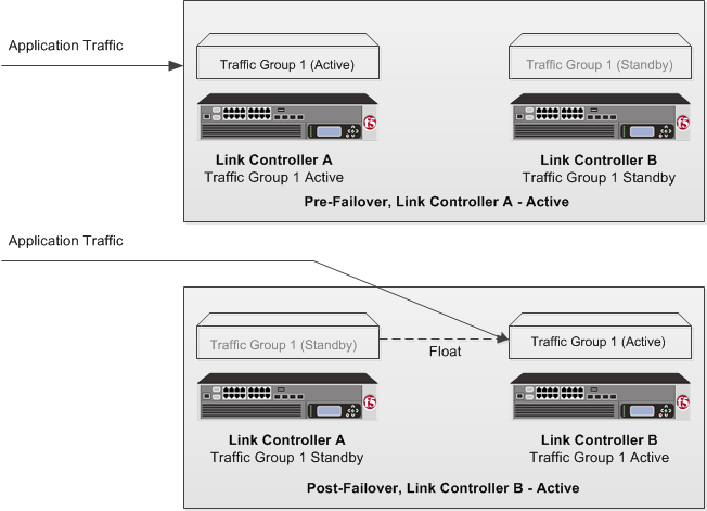
You can configure BIG-IP® Link Controller™ in an active-standby configuration, which is a set of two Link Controller systems: one operating as the active unit, the other operating as the standby unit. If the active unit in the active traffic group goes offline, the standby unit immediately assumes responsibility for managing traffic. The new active unit remains active until another event occurs that would cause the unit to go offline, or you manually reset the status of each unit.
This illustration shows Link Controller devices in an active-standby configuration.
Before you set up an active-standby BIG-IP®Link Controller™ configuration, you must configure these BIG-IP components on each device that you intend to include in the device group.
|
Configuration component |
Considerations |
|---|---|
|
Hardware, licensing, and provisioning |
Devices in a device group must match with respect to product licensing and module provisioning. Heterogeneous hardware platforms within a device group are supported. |
|
BIG-IP software version |
Each device must be running BIG-IP version 11.x. This ensures successful configuration synchronization. |
|
Management IP addresses |
Each device must have a management IP address, a network mask, and a management route defined. |
|
FQDN |
Each device must have a fully-qualified domain name (FQDN) as its host name. |
|
User name and password |
Each device must have a user name and password defined on it that you will use when logging in to the BIG-IP Configuration utility. |
|
|
The platform properties for the |
|
VLANs |
You must create these VLANs on each device, if you have not already done so:- A VLAN for the internal network, named
|
|
Self IP addresses |
You must create these self IP addresses on each device, if you have not already done so:- Two self IP addresses (floating and non-floating) on the same subnet for VLAN
Note: When you create floating self IP addresses, the BIG-IP system automatically adds them to the default floating traffic group, Important: If the BIG-IP device you are configuring is accessed using Amazon Web Services, then the IP address you specify must be the floating IP address for high availability fast failover that you configured for the EC2 instance. |
|
Port lockdown |
For self IP addresses that you create on each device, you should verify that the Port Lockdown setting is set to Allow All, All Default, or Allow Custom. Do not specify None. |
|
Application-related objects |
You must create any virtual IP addresses and optionally, SNAT translation addresses, as part of the local traffic configuration. You must also configure any iApp® application services if they are required for your application. When you create these addresses or services, the objects automatically become members of the default traffic group |
|
Time synchronization |
The times set by the NTP service on all devices must be synchronized. This is a requirement for configuration synchronization to operate successfully. |
|
Device certificates |
Verify that each device includes an x509 device certificate. Devices with device certificates can authenticate, and thus, trust one another, which is a prerequisite for device-to-device communication and data exchange. |
Before you begin this task, verify that:
- Each BIG-IP device that is to be part of the local trust domain has a device certificate installed on it.
- The local device is designated as a certificate signing authority.
Establish trust among devices on one or more network segments to constitute the local trust domain.
Note: A device must be a member of the local trust domain prior to joining a device group.
By default, the BIG-IP software includes a local trust domain with one member, which is the local device. You can choose any one of the BIG-IP devices slated for a device group and log into that device to add other devices to the local trust domain.
-
On the Main tab, click Device Management > Device Trust > Device Trust Members.
-
Click Add.
-
Type a device IP address, administrator user name, and administrator password for the remote BIG-IP device with which you want to establish trust. The IP address you specify depends on the type of BIG-IP device:
- If the BIG-IP device is an appliance, type a management IP address (IPv4 or IPv6) for the device.
- If the BIG-IP device is a VIPRION device that is not licensed and provisioned for vCMP, type a primary cluster management IP address (IPv4 or IPv6) for the cluster.
- If the BIG-IP device is a VIPRION device that is licensed and provisioned for vCMP, then type a cluster management IP address (IPv4 or IPv6) for the guest.
- If the BIG-IP device is an Amazon Web Services EC2 device, type one of the Private IP addresses created for this EC2 instance.
-
Click Retrieve Device Information.
-
Verify that the certificate of the remote device is correct, and then click Device Certificate Matches.
-
In the Name field, verify that the name of the remote device is correct.
-
Click Finished.
As a result of these steps, the local device is now a member of the local trust domain. Also, the BIG-IP system automatically creates a special Sync-Only device group for the purpose of synchronizing trust information among the devices in the local trust domain, on an ongoing basis.
Repeat these steps to specify each device that you want to add to the local trust domain.
Before configuring the config sync address, verify that all devices in the device group are running the same version of BIG-IP system software.
You perform this task to specify the IP address on the local device that other devices in the device group will use to synchronize their configuration objects to the local device.
Note: You must perform this task locally on each device in the device group.
-
Confirm that you are logged in to the device you want to configure.
-
On the Main tab, click Device Management > Devices.
This displays a list of device objects discovered by the local device.
-
In the Name column, click the name of the device to which you are currently logged in.
-
Near the top of the screen, click ConfigSync.
-
From the Local Address list, retain the displayed IP address or select another address from the list.
F5 Networks recommends that you use the default value, which is the self IP address for the internal VLAN. This address must be a non-floating (static) self IP address and not a management IP address.
Important: If the BIG-IP device you are configuring is accessed using Amazon Web Services, then the internal self IP address that you select must be an internal private IP address that you configured for this EC2 instance as the Local Address.
-
Click Update.
After performing this task, the other devices in the device group can synchronize their configurations to the local device whenever a sync operation is initiated.
Specify the local self IP address that you want other devices in a device group to use when mirroring their connections to this device. Connection mirroring ensures that in-process connections for an active traffic group are not dropped when failover occurs.
Note: You must perform these steps locally on each device in the device group.
-
Confirm that you are logged in to the device you want to configure.
-
On the Main tab, click Device Management > Devices.
This displays a list of device objects discovered by the local device.
-
In the Name column, click the name of the device to which you are currently logged in.
-
In the Name column, click the name of the device to which you are currently logged in.
-
Near the top of the screen, click Mirroring.
-
For the Primary Local Mirror Address setting, retain the displayed IP address or select another address from the list.
The recommended IP address is the self IP address for either VLAN
HAor VLANinternal.Important: If the BIG-IP device you are configuring is accessed using Amazon Web Services, then the self IP address you specify must be one of the private IP addresses that you configured for this EC2 instance as the Primary Local Mirror Address.
-
For the Secondary Local Mirror Address setting, retain the default value of None, or select an address from the list.
This setting is optional. The system uses the selected IP address in the event that the primary mirroring address becomes unavailable.
-
Click Update.
In addition to specifying an IP address for mirroring, you must also enable connection mirroring on the relevant virtual servers on this device.
Specify the local IP addresses that you want other devices in the device group to use for continuous health-assessment communication with the local device. You must perform the steps locally on each device in the device group.
Note: The IP addresses that you specify must belong to route domain 0.
-
Confirm that you are logged in to the device you want to configure.
-
On the Main tab, click Device Management > Devices.
This displays a list of device objects discovered by the local device.
-
In the Name column, click the name of the device to which you are currently logged in.
-
Near the top of the screen, click Failover Network.
-
For the Failover Unicast Configuration settings, click Add for each IP address on this device that other devices in the device group can use to exchange failover messages with this device. The unicast IP addresses you specify depend on the type of device:
Platform Action Appliance without vCMP Type a static self IP address associated with an internal VLAN (preferably VLAN HA) and the static management IP address currently assigned to the device.Appliance with vCMP Type a static self IP address associated with an internal VLAN (preferably VLAN HA) and the unique management IP address currently assigned to the guest.VIPRION without vCMP Type a static self IP address associated with an internal VLAN (preferably VLAN HA). If you choose to specify unicast addresses only (and not a multicast address), you must also type the existing, static management IP addresses that you previously configured for all slots in the cluster. If you choose to specify one or more unicast addresses and a multicast address, then you do not need to specify the existing, per-slot static management IP addresses when configuring addresses for failover communication.VIPRION with vCMP Type a self IP address that is defined on the guest and associated with an internal VLAN on the host (preferably VLAN HA). If you choose to specify unicast failover addresses only (and not a multicast address), you must also type the existing, virtual static management IP addresses that you previously configured for all slots in the guest’s virtual cluster. If you choose to specify one or more unicast addresses and a multicast address, you do not need to specify the existing, per-slot static and virtual management IP addresses when configuring addresses for failover communication.Important: Failover addresses should always be static, not floating, IP addresses.
-
To enable the use of a failover multicast address on a VIPRION platform (recommended), then for the Use Failover Multicast Address setting, select the Enabled check box.
-
If you enabled Use Failover Multicast Address, either accept the default Address and Port values, or specify values appropriate for the device.
If you revise the default Address and Port values, but then decide to revert to the default values, click Reset Defaults.
-
Click Update.
After you perform these steps, other devices in the device group can send failover messages to the local device using the specified IP addresses.
This task establishes failover capability between two or more BIG-IP devices. If an active device in a Sync-Failover device group becomes unavailable, the configuration objects fail over to another member of the device group and traffic processing is unaffected. You perform this task on any one of the authority devices within the local trust domain.
Repeat this task for each Sync-Failover device group that you want to create for your network configuration.
-
On the Main tab, click Device Management > Device Groups.
-
On the Device Groups list screen, click Create.
The New Device Group screen opens.
-
Type a name for the device group, select the device group type Sync-Failover, and type a description for the device group.
-
From the Configuration list, select Advanced.
-
For the Members setting, select a host name from the Available list for each BIG-IP device that you want to include in the device group, including the local device. Use the Move button to move the host name to the Includes list.
The Available list shows any devices that are members of the device’s local trust domain but not currently members of a Sync-Failover device group. A device can be a member of one Sync-Failover group only. Also, for vCMP-provisioned systems on platforms that contain a hardware security module (HSM) supporting FIPS multi-tenancy, the FIPS partitions on the guests in the device group must be identical with respect to the number of SSL cores allocated to the guest’s FIPS partition and the maximum number of private SSL keys that the guest can store on the HSM.
-
For the Network Failover setting, select or clear the check box:
- Select the check box if you want device group members to handle failover communications by way of network connectivity. This is the default value and is required for active-active configurations.
- Clear the check box if you want device group members to handle failover communications by way of serial cable (hard-wired) connectivity. For active-active configurations, you must select network failover, as opposed to serial-cable (hard-wired) connectivity.
-
For the Automatic Sync setting, specify whether configuration synchronization occurs manually or automatically:
- Select the check box when you want the BIG-IP system to automatically sync the BIG-IP configuration data whenever a config sync operation is required. In this case, the BIG-IP system syncs the configuration data whenever the data changes on any device in the device group.
- Clear the check box when you want to manually initiate each config sync operation. In this case, F5 networks recommends that you perform a config sync operation whenever configuration data changes on one of the devices in the device group.
-
For the Full Sync setting, specify whether the system synchronizes the entire configuration during synchronization operations:
- Select the check box when you want all sync operations to be full syncs. In this case, every time a config sync operation occurs, the BIG-IP system synchronizes all configuration data associated with the device group. This setting has a performance impact and is not recommended for most customers.
- Clear the check box when you want all sync operations to be incremental (the default setting). In this case, the BIG-IP system syncs only the changes that are more recent than those on the target device. When you select this option, the BIG-IP system compares the configuration data on each target device with the configuration data on the source device and then syncs the delta of each target-source pair. If you enable incremental synchronization, the BIG-IP system might occasionally perform a full sync for internal reasons. This is a rare occurrence and no user intervention is required.
-
In the Maximum Incremental Sync Size (KB) field, retain the default value of
1024, or type a different value.This value specifies the total size of configuration changes that can reside in the incremental sync cache. If the total size of the configuration changes in the cache exceeds the specified value, the BIG-IP system performs a full sync whenever the next config sync operation occurs.
-
Click Finished.
You now have a Sync-Failover type of device group containing BIG-IP devices as members.
Verify new traffic group membership to ensure that the IP addresses in the traffic group failover. Confirm that the same traffic group (typically the default traffic group, traffic-group-1) has all the the appropriate floating IP addresses, such as the internal and external self IP addresses, and a virtual IP address.
Note: You must perform these steps on each Link Controller device.
-
On the Main tab, click Device Management > Traffic Groups.
-
In the Name column, click the name of the traffic group for which you want to view the associated objects.
This displays a list of all failover objects for the traffic group.
-
In the Address column, for the traffic group selected, verify the listing of all of the appropriate floating IP addresses, including the internal and external self IP addresses, and a virtual IP address. If a SNAT address was created, also verify it is listed.
Before you sync the configuration, verify that the BIG-IP Link Controller devices targeted for config sync are members of a device group and that device trust is established.
Synchronize the BIG-IP configuration data from a local device to devices in a device group to ensure that all devices operate properly. When synchronizing self IP addresses, the BIG-IP system synchronizes floating self IP addresses only.
Important: You can perform these steps on either of the two devices, but not both.
-
On the Main tab, click Device Management > Overview.
-
In the Device Groups area of the screen, click the arrow next to the name of the relevant device group.
The screen expands to show a summary and details of the sync status of the selected device group, as well as a list of the individual devices within the device group.
-
In the Devices area of the screen, choose the device that shows a sync status of
Changes Pending. -
In the Sync Options area of the screen, select Push the selected device configuration to the group.
-
Click Sync.
The BIG-IP system syncs the configuration data of the selected device to the other members of the device group.
Except for non-floating self IP addresses, the entire set of BIG-IP configuration data is replicated on each device in the device group.
Enable global traffic synchronization options and create a name for the global traffic synchronization group.
Important: Perform these following steps only on the active system. The BIG-IP system will then synchronize the configuration data to the standby system.
-
On the Main tab, click System > Configuration > Global Traffic > General.
The General configuration screen opens.
-
Select the Synchronize check box.
-
Select the Synchronize DNS Zone Files check box.
-
In the Group Name field, type the name of the synchronization group.
-
Click Update.
Before you run the gtm_add script, make sure that the TCP port 4353 is available on both the active and standby systems.
Run the gtm_add script for the standby system to acquire the configuration established on the active system.
-
On the standby system, log in to the command-line interface.
-
Type
gtm_add, and press Enter. -
Press the y key to start the
gtm_addscript. -
Type the IP address of the active system.
-
Press Enter.
The
gtm_addprocess begins, acquiring configuration data from the active system.