


Updated Date: 07/07/2026
Manipulating HTTPS Traffic by Using a Third-Party Device
You can configure a BIG-IP® device to manage HTTPS traffic by using a third-party device that can intercept and modify the traffic, as necessary. This configuration provides SSL decryption, manipulation, and re-encryption while appearing relatively transparent at layer 2.
When you configure a virtual server to use the Transparent Nexthop control, traffic matching the virtual server is sent to the specified interface and the layer 2 addressing on the ingress packet is preserved. Configuring the Transparent Nexthop to specify the VLAN that is configured with the inspection device eliminates the need to configure a pool, NAT, SNAT, or other load balancing functionality to the inspection device.
Important: Transparent Nexthop functionality requires a license that supports that functionality. If the Transparent Nexthop control does not appear on the New Virtual Server screen, contact your F5 Networks support representative to acquire the necessary license.
The basic process used in this configuration is as follows:
- A client sends an HTTPS request to a server by means of the BIG-IP device.
- The BIG-IP device intercepts the request, decrypts it, and forwards the request as cleartext to the inspection device.
- The inspection device receives and, as necessary, modifies the cleartext request.
- The inspection device forwards the cleartext request to the server by means of the BIG-IP device.
- The BIG-IP device re-encrypts the cleartext request and sends the ciphertext request to the server.
- The server sends a response to the client by means of the BIG-IP device.
- The BIG-IP device receives the response, decrypts it, and forwards the response as cleartext to the inspection device.
- The inspection device receives and, as necessary, modifies the cleartext response.
- The inspection device forwards the cleartext response to the client by means of the BIG-IP device.
- The BIG-IP device re-encrypts the cleartext response and sends the ciphertext response to the client.
The following illustration shows an example of a BIG-IP device that manages HTTPS traffic modified by a third-party device.
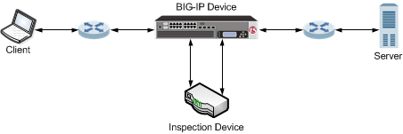
Complete these tasks to configure a BIG-IP® device to manage HTTPS traffic by using a third-party device that can intercept and modify the traffic, as necessary.
VLANs represent a logical collection of hosts that can share network resources, regardless of their physical location on the network. You create a VLAN to associate physical interfaces with that VLAN.
-
On the Main tab, click Network > VLANs.
The VLAN List screen opens.
-
Click Create.
The New VLAN screen opens.
-
In the Name field, type a unique name for the VLAN.
-
In the Tag field, type a numeric tag, between 1-4094, for the VLAN, or leave the field blank if you want the BIG-IP system to automatically assign a VLAN tag.
The VLAN tag identifies the traffic from hosts in the associated VLAN.
-
If you want to use Q-in-Q (double) tagging, use the Customer Tag setting to perform the following two steps. If you do not see the Customer Tag setting, your hardware platform does not support Q-in-Q tagging and you can skip this step.
-
From the Customer Tag list, select Specify.
-
Type a numeric tag, from 1-4094, for the VLAN.
The customer tag specifies the inner tag of any frame passing through the VLAN.
-
-
For the Interfaces setting,
-
From the Interface list, select an interface number.
-
From the Tagging list, select Untagged.
-
Click Add.
-
-
For the Hardware SYN Cookie setting, select or clear the check box.
When you enable this setting, the BIG-IP system triggers hardware SYN cookie protection for this VLAN.
Enabling this setting causes additional settings to appear. These settings appear on specific BIG-IP platforms only.
-
For the Syncache Threshold setting, retain the default value or change it to suit your needs.
The Syncache Threshold value represents the number of outstanding SYN flood packets on the VLAN that will trigger the hardware SYN cookie protection feature.
When the Hardware SYN Cookie setting is enabled, the BIG-IP system triggers SYN cookie protection in either of these cases, whichever occurs first:
- The number of TCP half-open connections defined in the LTM setting Global SYN Check Threshold is reached.
- The number of SYN flood packets defined in this Syncache Threshold setting is reached.
-
For the SYN Flood Rate Limit setting, retain the default value or change it to suit your needs.
The SYN Flood Rate Limit value represents the maximum number of SYN flood packets per second received on this VLAN before the BIG-IP system triggers hardware SYN cookie protection for the VLAN.
-
Click Finished.
The screen refreshes, and displays the new VLAN in the list.
You create a custom Client SSL profile when you want the BIG-IP system to terminate client-side SSL traffic for the purpose of:
- Authenticating and decrypting ingress client-side SSL traffic
- Re-encrypting egress client-side traffic
By terminating client-side SSL traffic, the BIG-IP system offloads these authentication and decryption/encryption functions from the destination server.
-
On the Main tab, click Local Traffic > Profiles > SSL > Client.
The Client SSL profile list screen opens.
-
Click Create.
The New Client SSL Profile screen opens.
-
In the Name field, type a unique name for the profile.
-
Select clientssl in the Parent Profile list.
-
Select the Proxy SSL check box (the rest of the UI will collapse following this setting).
-
Optionally, select the Proxy SSL Passthrough check box.
Note: This option is often not needed. Review the Knowledge Center article K13385: Overview of the Proxy SSL feature for guidelines on when to enable this setting and its implications.
-
Configure the Certificate Key Chain.
Note: The Certificate and Key under ClientSSL profile are not used in Proxy SSL (since the client and the server will eventually verify each other). F5 recommends leaving the default F5 cert/key pair.
-
Click Finished.
Create a custom server SSL profile to support SSL forward proxy.
-
On the Main tab, click Local Traffic > Profiles > SSL > Server.
The Server SSL profile list screen opens.
-
Click Create.
The New Server SSL Profile screen opens.
-
In the Name field, type a unique name for the profile.
-
For Parent Profile, retain the default selection, serverssl.
-
Select the Proxy SSL check box (the rest of the UI will collapse following this setting).
-
Optionally, select the Proxy SSL Passthrough check box.
Note: This option is often not needed. Review the Knowledge Center article K13385: Overview of the Proxy SSL feature for guidelines on when to enable this setting and its implications.
-
Configure the Certificate and Key using the identical Certificate and Key details configured on the server.
Note: Import the details to the BIG-IP system prior to configuring Proxy SSL.
-
Click Finished.
The custom Server SSL profile is now listed in the SSL Server profile list.
Complete these tasks to configure a BIG-IP® device to manage HTTPS traffic by using a third-party device that can intercept and modify the traffic, as necessary.
You can specify a virtual server that manages clientside HTTPS traffic sent to a third-party device to manipulate traffic.
-
On the Main tab, click Local Traffic > Virtual Servers.
The Virtual Server List screen opens.
-
Click Create.
The New Virtual Server screen opens.
-
In the Name field, type a unique name for the virtual server.
-
From the Type list, select Standard.
-
For the Destination Address/Mask setting, confirm that the Host button is selected, and type the IP address in CIDR format.
The supported format is address/prefix, where the prefix length is in bits. For example, an IPv4 address/prefix is
10.0.0.1or10.0.0.0/24, and an IPv6 address/prefix isffe1::0020/64or2001:ed8:77b5:2:10:10:100:42/64. When you use an IPv4 address without specifying a prefix, the BIG-IP system automatically uses a/32prefix.Note: The IP address you type must be available and not in the loopback network.
-
For the Service Port setting, type
443in the field, or select HTTPS from the list. -
From the Protocol Profile (Client) list, select splitsession-default-tcp.
-
From the Configuration list, select Advanced.
-
From the HTTP Profile list, select http.
-
For the SSL Profile (Client) setting, from the Available list, select a Client SSL profile, and using the Move button, move the name to the Selected list.
-
From the VLAN and Tunnel Traffic list, select Enablerd on.
-
For the VLANs and Tunnels setting, move the clientside VLAN to the Selected list.
-
From the Transparent Nexthop list, select the VLAN that you created for the inspection device.
-
Click Finished.
The clientside HTTPS virtual server appears in the Virtual Server List screen.
You can specify a virtual server that manages serverside traffic sent from a third-party device to manipulate traffic.
-
On the Main tab, click Local Traffic > Virtual Servers.
The Virtual Server List screen opens.
-
Click Create.
The New Virtual Server screen opens.
-
In the Name field, type a unique name for the virtual server.
-
From the Type list, select Standard.
-
For the Destination Address/Mask setting, confirm that the Host button is selected, and type the IP address in CIDR format.
The supported format is address/prefix, where the prefix length is in bits. For example, an IPv4 address/prefix is
10.0.0.1or10.0.0.0/24, and an IPv6 address/prefix isffe1::0020/64or2001:ed8:77b5:2:10:10:100:42/64. When you use an IPv4 address without specifying a prefix, the BIG-IP system automatically uses a/32prefix.Note: The IP address you type must be available and not in the loopback network.
-
For theService Port setting, type
80in the field, or select HTTP from the list. -
From the Configuration list, select Advanced.
-
From the Protocol Profile (Server) list, select splitsession-default-tcp.
-
From the HTTP Profile list, select http.
-
For the SSL Profile (Server) setting, from the Available list, select a Server SSL profile, and using the Move button, move the name to the Selected list.
-
From the VLAN and Tunnel Traffic list, select Enabled on.
-
For the VLANs and Tunnels setting, move the VLAN that you created for the inspection device to the Selected list.
-
From the Transparent Nexthop list, select the serverside VLAN.
-
Click Finished.
The serverside HTTPS virtual server appears in the Virtual Server List screen.
VLAN groups consolidate Layer 2 traffic from two or more separate VLANs.
-
On the Main tab, click Network > VLANs > VLAN Groups.
The VLAN Groups list screen opens.
-
From the VLAN Groups menu, choose List.
-
Click Create.
The New VLAN Group screen opens.
-
In the General Properties area, in the VLAN Group field, type a unique name for the VLAN group.
-
For the VLANs setting, from the Available field select the internal and external VLAN names, and click << to move the VLAN names to the Members field.
-
Click Finished.