Updated Date: 07/07/2026
Configuring the BIG-IP System for Passive Monitoring
You can configure a physical interface on a BIG-IP system to operate in passive mode. In this mode, the interface accepts mirrored traffic from another device to collect data for analysis and intrusion detection.
Important: The following hardware platform series do not support passive monitoring: 2000, 4000, i2000 and i4000.
The BIG-IP system analyzes the mirrored traffic, drops it, and then sends the resulting analytics data and log messages to a remote analytics and logging server. The mirrored traffic never leaves the system, and the BIG-IP system never acts on the headers and payload.
You don’t need to deploy the BIG-IP system in line with your BIG-IP application delivery controller (ADC), which means there’s no need to make changes to your network infrastructure.
This illustration shows a configuration that includes a BIG-IP passive monitoring system.
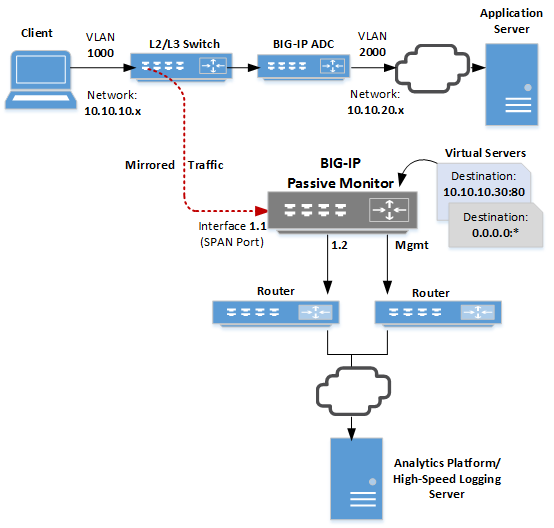
As we see in the illustration, a Layer 2/Layer 3 switch receives client traffic on the 10.10.10.x network. The traffic comes into the switch, which mirrors it to a SPAN port on the BIG-IP system. A SPAN port is an interface that can receive traffic mirrored to it from another device.
After analyzing the traffic, the BIG-IP system forwards all analytics data and log messages through interface 1.2 to a remote analytics and logging server and then discards its copy of the application traffic.
We’ve also configured two virtual servers to listen on the SPAN port. One virtual server listens for any mirrored HTTP traffic destined for a particular destination address on port 80, while the other listens for any traffic not caught by the HTTP virtual server.
Typical reasons for deploying a BIG-IP system as a passive monitoring device are:
- To collect HTTP analytics data
- To analyze mirrored traffic using a configured Application Security Manager (ASM) security policy. For more information, see the guide titled BIG-IP Application Security Manager: Implementations on the F5 website
http://support.f5.com. - To collect application analytics data along with Subscriber-awareness made available by BIG-IP Policy Enforcement Manager™ (PEM™)
- To enable firewall services that report on possible infringements
- To detect denial-of-service attacks with signaling to some external entity for triggering actions
- To perform intrusion detection services
- To perform behavioral analysis
Before you set up a BIG-IP system as a passive monitoring system, make sure you have:
- Configured a network device, such as a Layer 2/Layer 3 switch, configured to receive client application traffic and mirror it to the BIG-IP passive monitoring system.
- Created a user account with a user role that grants permission to perform all tasks (Administrator, Resource Administrator, or Manager).
- Provisioned the optional BIG-IP AVR module.
- A BIG-IP system operating in passive mode can accept mirrored traffic either raw or tunneled. In the case of tunneled traffic, the tunnel must be terminated on the BIG-IP system prior to the system analyzing the traffic.
- Global statistics do not differentiate between mirrored traffic and active traffic. However, statistics for an individual virtual server do differentiate between mirrored and active traffic because a virtual server applies to one type of traffic only.
- The following hardware platform series do not support passive monitoring: 2000, 4000, i2000 and i4000.
- A trunk on which Link Aggregation Control Protocol (LACP) is enabled cannot operate as a passive monitoring interface.
- When you assign a passive monitoring interface to a BIG-IP VLAN, any self IP addresses associated with that VLAN will no longer respond to ARP requests.
To configure the BIG-IP system to do passive monitoring, you designate an interface on the BIG-IP passive monitoring system as a SPAN port and assign the interface to the ingress VLAN. Then, you create a Fast L4 profile and a TCP profile to disable SYN cookie support and/or Packet Velocity Asic (PVA) acceleration. Finally, you set up two virtual servers, a standard virtual server to listen for mirrored HTTP traffic, and a Performance (Layer 4) virtual server to listen for all other mirrored traffic.
The result is that the system analyzes ingress traffic and sends log messages and analytics data to a remote analytics and high-speed logging server.
Important: The following hardware platform series do not support passive monitoring: 2000, 4000, i2000 and i4000.
You can designate a physical interface on the BIG-IP ® system as a SPAN port. A SPAN port receives mirrored traffic for the purpose of doing passive monitoring of that traffic. Through passive monitoring, the system can collect data for the purpose of analytics or intrusion detection.
Note: You can configure a trunk for passive monitoring. In this case, you must set the Forwarding Mode to Passive separately on each link of the trunk.
-
On the Main tab, click Network > Interfaces > Interface List.
The Interface List screen displays the list of interfaces on the system.
-
In the Name column, click an interface number.
This displays the properties of the interface.
-
For the State setting, verify that the interface is set to Enabled.
-
From the Forwarding Mode list, select Passive.
If you do not see the Passive option, your hardware platform does not support passive monitoring. The following hardware platform series do not support passive monitoring: 2000, 4000, i2000 and i4000.
-
Click the Update button.
Before performing this task, make sure that you have configured a VLAN with a tagged interface on the upstream switch that will mirror ingress application traffic and send it to this BIG-IP system.
For any BIG-IP interface that you’ve configured to receive mirrored application traffic, you must create a VLAN and assign the interface to the VLAN.
-
On the Main tab, click Network > VLANs.
The VLAN List screen opens.
-
Click Create.
-
In the Name field, type a name for the VLAN.
-
In the VLAN ID field, type the same VLAN ID that you configured on the VLAN of the upstream switch that will send mirrored traffic to this BIG-IP system.
-
For the Interfaces setting:
-
From the Interface list, select the interface that you previously set to Passive forwarding mode.
Be sure to do this step; otherwise, the interface remains in an uninitialized state.
-
From the Tagging list, select Tagged.
Important: This is the recommended configuration.
-
Click Add.
-
-
Click Finished.
The BIG-IP system now has a VLAN capable of receiving mirrored application traffic from an an upstream switch on the network.
You create a Fast L4 profile to disable the Packet Velocity® ASIC settings and disable the SYN Challenge Handling setting.
-
On the Main tab, click Local Traffic > Profiles > Protocol > Fast L4.
The screen displays a list of Fast L4 profiles.
-
Click Create.
-
In the Name field, type a name for the profile.
An example of a profile name is
my_fastl4_profile. -
On the right side of the screen, select the Custom check box.
-
From the PVA Acceleration list, select None.
If you do not see this setting, your hardware platform does not support Packet Velocity ASIC, and you can skip this step.
-
For the PVA Offload Dynamic setting, clear the check box.
If you do not see this setting, your hardware platform does not support Packet Velocity ASIC, and you can skip this step.
-
From the SYN Challenge Handling list, select Disable Challenges.
-
Click Finished.
After completing these steps, the BIG-IP system has a Fast L4 profile for filtering mirrored traffic coming into the system through a SPAN port.
You create an HTTP virtual server on a BIG-IP passive monitoring device to intercept specific mirrored HTTP traffic. This is traffic that you want to collect analytics and intrustion detection data on and then forward the data to a remote server.
-
On the Main tab, click Local Traffic > Virtual Servers.
The Virtual Server List screen opens.
-
Click Create.
The New Virtual Server screen opens.
-
In the Name field, type a unique name for the virtual server.
-
From the Type list, select Performance (Layer 4).
-
In the Source Address field, type
0.0.0.0/0. -
In the Destination Address/Mask field, type the destination address found in the destination IP address header of specific HTTP traffic that gets mirrored to the BIG-IP passive monitoring system.
For example, if client traffic is destined for the IP address
10.10.10.30, the BIG-IP passive monitoring system can listen for mirrored traffic with this destination address in its header in order to receive and analyze the mirrored traffic. -
In the Service Port field, type
80, or select HTTP from the list. -
From the Configuration list, select Advanced.
-
From the Protocol list, select TCP.
-
From the Protocol Profile (Client) list, select the name of the Fast L4 profile you created earlier.
-
From the HTTP Profile list, select the default HTTP profile named http.
If you’d rather assign a custom profile, create a new HTTP profile before you create this virtual server, and then select the profile from this list.
-
From the VLAN and Tunnel Traffic list, retain the default selection, All VLANs and Tunnels.
-
For the Address Translation setting, verify that the check box is cleared.
-
For the Port Translation setting, verify that the check box is cleared.
-
From the HTTP Analytics Profile list, select analytics.
-
From the TCP Analytics Profile list, select tcp-analytics.
-
Click Finished.
You now have a virtual server configured to accept specific mirrored HTTP traffic coming into the interface designated as a SPAN port.
You can create a wildcard virtual server (also known as a listener) on the BIG-IP® passive monitoring device. The purpose of a wildcard virtual server is to intercept any mirrored traffic that the other virtual servers on the BIG-IP passive monitoring device don’t already intercept. Once the wildcard virtual server receives the traffic, it can monitor the traffic for analytics and intrusion detection.
-
On the Main tab, click Local Traffic > Virtual Servers.
The Virtual Server List screen opens.
-
Click Create.
The New Virtual Server screen opens.
-
In the Name field, type a unique name for the virtual server.
-
From the Type list, select Performance (Layer 4).
-
In the Source Address field, type
0.0.0.0/0. -
In the Destination Address/Mask field, type
0.0.0.0to accept any IPv4 traffic. -
In the Service Port field, type
*or select * All Ports from the list. -
From the Configuration list, select Advanced.
-
From the Protocol list, select TCP.
-
From the Protocol Profile (Client) list, select the name of the Fast L4 profile you created for filtering mirrored traffic.
-
From the VLAN and Tunnel Traffic list, retain the default selection, All VLANs and Tunnels.
-
For the Address Translation setting, verify that the check box is cleared.
-
For the Port Translation setting, verify that the check box is cleared.
-
From the HTTP Analytics Profile list, select analytics.
-
From the TCP Analytics Profile list, select tcp-analytics.
-
Click Finished.
You now have a virtual server configured to accept all traffic coming in through the interface designated as a SPAN port, except for traffic that specifically matches another virtual server on the system.
Before creating a pool of log servers, gather the IP addresses of the servers that you want to include in the pool. Ensure that the remote log servers are configured to listen to and receive log messages from the BIG-IP® system.
You create a pool of remote log servers to which the BIG-IP system can send log messages.
-
On the Main tab, click the applicable path.
- DNS > Delivery > Load Balancing > Pools
- Local Traffic > Pools The Pool List screen opens.
-
Click Create.
The New Pool screen opens.
-
In the Name field, type a unique name for the pool.
-
Using the New Members setting, add the IP address for each remote logging server that you want to include in the pool:
-
Type an IP address in the Address field, or select a node address from the Node List.
-
Type a service number in the Service Port field, or select a service name from the list.
Note: Typical remote logging servers require port
514. -
Click Add.
-
-
Click Finished.
Before creating a remote high-speed log destination, ensure that at least one pool of remote log servers exists on the BIG-IP system.
You create a log destination of the Remote High-Speed Log type to specify that log messages are sent to a pool of remote log servers.
-
On the Main tab, click System > Logs > Configuration > Log Destinations.
The Log Destinations screen opens.
-
Click Create.
-
In the Name field, type a unique, identifiable name for this destination.
-
From the Type list, select Remote High-Speed Log.
Important: If you use log servers such as Remote Syslog, Splunk, or ArcSight, which require data be sent to the servers in a specific format, you must create an additional log destination of the required type, and associate it with a log destination of the Remote High-Speed Log type. With this configuration, the BIG-IP system can send data to the servers in the required format.
The BIG-IP system is configured to send an unformatted string of text to the log servers.
-
From the Pool Name list, select the pool of remote log servers to which you want the BIG-IP system to send log messages.
-
From the Protocol list, select the protocol used by the high-speed logging pool members.
-
Click Finished.
Before you start this task, ensure that at least one remote high-speed log destination exists on the BIG-IP® system.
You create a formatted logging destination to specify that log messages are sent to a pool of remote log servers, such as Remote Syslog, Splunk, or ArcSight servers.
-
On the Main tab, click System > Logs > Configuration > Log Destinations.
The Log Destinations screen opens.
-
Click Create.
-
In the Name field, type a unique, identifiable name for this destination.
-
From the Type list, select a formatted logging destination, such as IPFIX, Remote Syslog, Splunk, or ArcSight.
Important: ArcSight formatting is only available for logs coming from Advanced Firewall Manager (AFM), Application Security Manager (ASM), and the Secure Web Gateway component of Access Policy Manager (APM). IPFIX is not available for Secure Web Gateway. Remote Syslog formatting is the only type supported for logs coming from APM. The Splunk format is a predefined format of key value pairs.
The BIG-IP system is configured to send a formatted string of text to the log servers.
-
If you selected Remote Syslog, then from the Syslog Format list select a format for the logs, and then from the High-Speed Log Destination list, select the destination that points to a pool of remote Syslog servers to which you want the BIG-IP system to send log messages.
Important: For logs coming from Access Policy Manager (APM), only the BSD Syslog format is supported.
-
If you selected Splunk or IPFIX, then from the Forward To list, select the destination that points to a pool of high-speed log servers to which you want the BIG-IP system to send log messages.
-
Click Finished.
Before you start this task, ensure that at least one destination associated with a pool of remote log servers exists on the BIG-IP system.
You can create a publisher to specify where the BIG-IP system sends log messages for specific resources.
-
On the Main tab, click System > Logs > Configuration > Log Publishers.
The Log Publishers screen opens.
-
Click Create.
-
In the Name field, type a unique, identifiable name for this publisher.
-
For the Destinations setting, select a destination from the Available list, and move the destination to the Selected list.
Note: If you are using a formatted destination, select the destination that matches your log servers, such as Remote Syslog, Splunk, or ArcSight.
-
Click Finished.
Before you start this task, ensure that at least one log publisher is configured on the BIG-IP system.
You create a custom log filter to specify the system log messages that you want to publish to a particular log.
-
On the Main tab, click System > Logs > Configuration > Log Filters.
The Log Filters screen opens.
-
Click Create.
-
In the Name field, type a unique, identifiable name for this filter.
-
From the Severity list, select the level of alerts that you want the system to use for this filter.
Note: The severity level that you select includes all of the severity levels that display above your selection in the list. For example, if you select Emergency, the system publishes only emergency messages to the log. If you select Critical, the system publishes critical, alert, and emergency-level messages in the log.
-
From the Source list, select the system processes from which messages will be sent to the log.
-
In the Message ID field, type the first eight hex-digits of the specific message ID that you want the system to include in the log. Use this field when you want a log to contain only each instance of one specific log message.
Note: BIG-IP system log messages contain message ID strings in the format:
xxxxxxxx:x:. For example, in this log message:Oct 31 11:06:27 olgavmmgmt notice mcpd[5641]: 01070410:5: Removed subscription with subscriber id lind, the message ID string is:01070410:5:. You enter only the first eight hex-digits:01070410. -
From the Log Publisher list, select the publisher that includes the destinations to which you want to send log messages.
-
Click Finished.
When you no longer want the BIG-IP system to log information about its internal systems, you can delete the log filter that you created. For example, when mitigating a DoS attack, if you created a log filter that includes only one specific message in the log, you can delete that log filter once you handle the attack.
-
On the Main tab, click System > Logs > Configuration > Log Filters.
The Log Filters screen opens.
-
Select the check box next to the name of the log filter that you want to delete. Click Delete, and then click Delete again.