Updated Date: 07/07/2026
Initial VIPRION Setup
After hardware installation is completed, you are ready to create a basic BIG-IP® software configuration.
Important: Prior to configuring the BIG-IP software, verify that you have cabled the management interfaces of all slots to all of the blades, to minimize any interruption in service if a blade becomes unavailable.
The first step in configuring the BIG-IP software is to run the Setup utility to perform tasks such as activating the BIG-IP system license and provisioning BIG-IP modules. You then set up a base BIG-IP system network consisting of trunks, VLANs, and self IP addresses, as well as a management IP address for each blade in the VIPRION® cluster. You also define your Domain Name System (DNS) servers and your NTP servers.
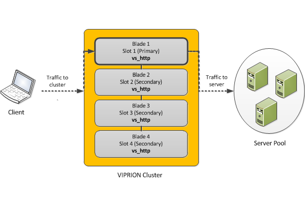
This illustration shows a basic VLAN and trunk configuration for a standalone VIPRION system. In the illustration, the VIPRION chassis is configured with a cluster containing two active blades. Note that each VLAN consists of two interfaces, one per slot. After setting up this basic configuration, you can adjust the configuration later as needed.
During VIPRION® setup, before you provision the system, you must decide:
- If you’re going to provision the system to run the Virtual Clustered Multiprocessing (vCMP®) feature
- Whether you want vCMP to consume the standard amount of disk space for vCMP on each blade
The total disk space that the system normally allocates to vCMP is determined by the size of each application volume (one per blade) that the system creates during vCMP provisioning.
By default, the BIG-IP system allocates all but 30 gigabytes of reserve disk space per blade to vCMP. Reserve disk space is the amount of disk space that the system reserves for other uses during provisioning, such as for installing other versions of the BIG-IP® system in the future. The reserved disk space also protects against any potential resizing of the file system.
Important: You can change the reserve disk space for a vCMP application volume if you think that 30 gigabytes won’t be sufficient, but you must do this before you provision the system for vCMP.
Use this procedure to increase the amount of reserve disk space on a vCMP application volume. Increasing reserve disk space allows you to install additional versions of the BIG-IP system, and protects against any potential resizing of the file system. The default reserve disk space is 30 gigabytes.
Important: You must do this task before you provision the system for vCMP.
Note: When increasing the reserve disk space for additional BIG-IP installations, we recommend that you reserve 8 gigabytes per installation.
-
In the URL field, type the management IP address that you previously assigned to the system.
https://*<ip\_address>*The browser displays the login screen for the BIG-IP Configuration utility.
-
On the Main tab, click System > Disk Management.
The display shows the logical disks and application volumes from the perspective of the vCMP host.
-
Click the logical disk for which you want to reserve disk space.
An example of a logical disk is
HD1. -
On the menu bar, click Image List if displayed.
The screen displays a list of the installed images on the system.
-
If a list of images appears, locate the relevant image, and in the Disk column, click the logical disk name.
-
In the Reserved (MB) field, increase the amount of disk space that you want to reserve for the logical disk.
The more space you reserve, the less disk space there is available for the vCMP application volume.
-
Click Update.
Before you begin, confirm that you have done the following:
- Cabled the management interfaces of all slots in the chassis to all blades.
- Obtained the BIG-IP® base registration key.
- If you intend to provision the system for vCMP®, verified that the vCMP application volume has adequate reserve disk space for your system needs; you cannot adjust the reserve disk space after provisioning the system for vCMP.
Use this procedure to open the Setup utility and perform some basic, system- and network-level setup tasks. These tasks are a required part of initially configuring the BIG-IP software on the VIPRION® platform.
-
From a workstation attached to the management network, type the management IP address, using the following URL syntax:
https://*<management\_IP\_address>* -
At the login prompt, type the default user name
admin, and passwordadmin, and click Log in.The Setup utility screen opens.
-
Click Next.
The General Properties screen opens.
-
Click Activate.
The License screen opens.
-
In the Base Registration Key field, paste the registration key.
You received your registration key when you purchased the BIG-IP device or module.
-
Click Next.
-
Provision the selected BIG-IP modules (or the vCMP feature) to Nominal.
If you are provisioning the vCMP feature, the BIG-IP® system allocates disk space for vCMP. By default, reserves 30 gigabytes of the total disk space for other uses, such as for installing additional versions of the BIG-IP system in the future. Before you provision vCMP, make sure the default reserved disk space is adequate for your needs; you cannot adjust the reserve disk space after provisioning the system for vCMP.
Important: When increasing the reserve disk space for additional BIG-IP installations, the recommended amount of space to reserve is 8 gigabytes per installation.
-
Click Next.
The device certificate is displayed.
-
Click Next.
The General Properties and User Administration screen opens.
-
For the Management Port 1 Configuration setting, confirm that Manual is selected.
Note: The VIPRION platform does not support automatic assignment of primary management IP addresses.
-
For the Cluster IP Address fields, confirm that one of the fields displays the floating primary cluster management IP address that you assigned with the LCD panel when setting up the VIPRION hardware.
Note: These addresses are used to log in to the VIPRION system to manage the system as a whole. If the primary blade goes down, this address floats to an available blade in the chassis. You have the option to reconfigure these addresses on the next screen of the Setup utility.
-
In the Host Name field, type the host name of this BIG-IP system.
For example,
www.siterequest.com. -
For the Time Zone setting, ensure that the correct time zone is selected.
-
For the Root Account setting, type and confirm a password for the root account.
-
Click Next.
-
For the Management IP Address setting, configure the value of the IP Address, Network Mask, and Management Route fields.
Note: This is a floating primary cluster management IP address.
-
For the Cluster Member IP Address setting, specify or confirm a management IP address for each slot in the chassis.
F5 Networks recommends that you specify an address for every slot in the chassis, regardless of the number of active cluster members. Doing so provides an IP address for any additional blades that you might install in the future. Also, make sure that these addresses are on the same subnet as the floating primary cluster management IP address.
-
For the Alternate Management IP Address setting (optional), configure alternate values for the IP Address, Network Mask, and Management Route fields.
Note: This is an alternate floating primary cluster mangement IP address.
-
If you configured the Alternate Management IP Address setting, then for the Alternate Cluster Member IP Address setting, specify an alternate management IP address for each slot in the chassis.
-
Click Next.
-
Click Finished.
For VIPRION® platforms, F5 Networks® strongly recommends that you create a trunk for each of the BIG-IP® system internal and external networks, and that each trunk contains interfaces from all slots in the cluster.
For example, a trunk for the external network should contain the external interfaces of all blades in the cluster. Configuring a trunk in this way prevents interruption in service if a blade in the cluster becomes unavailable and minimizes use of the high-speed backplane when processing traffic.
Also, you should connect the links in a trunk to a vendor switch on the relevant network.
Important: When processing egress packets, including those of vCMP® guests, the BIG-IP system uses trunk member interfaces on local blades whenever possible. This behavior ensures efficient use of the backplane, thereby conserving backplane bandwidth for processing ingress packets.
You create a trunk on the BIG-IP® system so that the system can then aggregate the links to enhance bandwidth and ensure link availability.
The maximum number of interfaces that you can configure in a trunk is 16 or 32, depending on your specific BIG-IP platform and software version. For optimal performance, you should aggregate links in powers of two.
-
On the Main tab, click Network > Trunks.
The Trunk List screen opens.
-
Click Create.
-
Name the trunk.
-
For the Interfaces setting, in the Available field, select an interface, and using the Move button, move the interface to the Members field. Repeat this action for each interface that you want to include in the trunk.
Trunk members must be untagged interfaces and cannot belong to another trunk. Therefore, only untagged interfaces that do not belong to another trunk appear in the Available list.
-
Select the LACP check box.
-
Click Finished.
After you create a trunk, the BIG-IP system aggregates the links to enhance bandwidth and prevent interruption in service.
For the most basic BIG-IP® system configuration with redundancy enabled, you typically create multiple VLANs. That is, you create a VLAN for each of the internal and external networks, as well as a VLAN for high availability communications. You then associate each VLAN with the relevant interfaces of all cluster members on that network.
For example, for a system with a two-slot cluster, you might associate the external VLAN with interfaces 2.1/1 and 2.1/2, where 2.1/1 is on slot 1 and 2.1/2 is on slot 2.
If your hardware platform supports ePVA, you have the additional option of configuring double tagging (also known as Q-in-Q tagging) for a VLAN.
VLANs represent a logical collection of hosts that can share network resources, regardless of their physical location on the network. You create a VLAN to associate physical interfaces with traffic destined for a specific address space. For the most basic BIG-IP® system configuration with redundancy enabled, you typically create multiple VLANs. That is, you create a VLAN for each of the internal and external networks, as well as a VLAN for high availability communications. If your hardware platform supports ePVA, you have the additional option of configuring double tagging (also known as Q-in-Q tagging) for a VLAN.
-
On the Main tab, click Network > VLANs.
The VLAN List screen opens.
-
Click Create.
The New VLAN screen opens.
-
In the Name field, type a unique name for the VLAN.
-
In the Tag field, type a numeric tag, between 1-4094, for the VLAN, or leave the field blank if you want the BIG-IP system to automatically assign a VLAN tag.
The VLAN tag identifies the traffic from hosts in the associated VLAN.
-
From the Customer Tag list:
-
Retain the default value of None or select Specify.
-
If you chose Specify in the previous step, type a numeric tag, between 1-4094, for the VLAN.
The customer tag specifies the inner tag of any frame passing through the VLAN.
-
-
For the Interfaces setting:
-
From the Interface list, select an interface number or trunk name.
-
From the Tagging list, select Tagged or Untagged.
Select Tagged when you want traffic for that interface to be tagged with a VLAN ID.
-
If you specified a numeric value for the Customer Tag setting and from the Tagging list you selected Tagged, then from the Tag Mode list, select a value.
-
Click Add.
-
Repeat these steps for each interface or trunk that you want to assign to the VLAN.
-
-
If you want the system to verify that the return route to an initial packet is the same VLAN from which the packet originated, select the Source Check check box.
-
In the MTU field, retain the default number of bytes (1500).
-
From the Configuration list, select Advanced.
-
If you want to base redundant-system failover on VLAN-related events, select the Fail-safe check box.
-
From the Auto Last Hop list, select a value.
-
From the CMP Hash list, select a value.
-
To enable the DAG Round Robin setting, select the check box.
-
For the Hardware SYN Cookie setting, select or clear the check box.
When you enable this setting, the BIG-IP system triggers hardware SYN cookie protection for this VLAN.
Enabling this setting causes additional settings to appear. These settings appear on specific BIG-IP platforms only.
-
For the Syncache Threshold setting, retain the default value or change it to suit your needs.
The Syncache Threshold value represents the number of outstanding SYN flood packets on the VLAN that will trigger the hardware SYN cookie protection feature.
When the Hardware SYN Cookie setting is enabled, the BIG-IP system triggers SYN cookie protection in either of these cases, whichever occurs first:
- The number of TCP half-open connections defined in the LTM setting Global SYN Check Threshold is reached.
- The number of SYN flood packets defined in this Syncache Threshold setting is reached.
-
For the SYN Flood Rate Limit setting, retain the default value or change it to suit your needs.
The SYN Flood Rate Limit value represents the maximum number of SYN flood packets per second received on this VLAN before the BIG-IP system triggers hardware SYN cookie protection for the VLAN.
-
Configure the sFlow settings or retain the default values.
-
Click Finished.
The screen refreshes, and displays the new VLAN in the list.
After you create the VLAN, you can assign the VLAN to a self IP address.
After creating the VLAN, ensure that you repeat this task to create as many VLANs as needed.
When you do not intend to provision the vCMP® feature, you typically create self IP addresses when you initially configure the BIG-IP® system on the VIPRION® platform.
If you plan to provision vCMP, you do not need to create self IP addresses during initial BIG-IP configuration. Instead, the host administrator creates VLANs for use by guests, and the guest administrators create self IP addresses to associate with those VLANs.
Before you create a self IP address, ensure that you have created a VLAN that you can associate with the self IP address.
A self IP address that you create within a guest enables the guest to route application traffic through the associated VLAN or VLAN group. On vCMP systems, a guest administrator creates self IP addresses and associates them with VLANs created on the host that a host administrator published to the guest during initial guest creation.
-
On the Main tab, click Network > Self IPs.
-
Click Create.
The New Self IP screen opens.
-
In the Name field, type a unique name for the self IP address.
-
In the IP Address field, type an IPv4 or IPv6 address.
This IP address should represent the address space of the VLAN that you specify with the VLAN/Tunnel setting.
-
In the Netmask field, type the network mask for the specified IP address.
For example, you can type
255.255.255.0. -
From the VLAN/Tunnel list, select the VLAN to associate with this self IP address.
- On the internal network, select the internal or high availability VLAN that is associated with an internal interface or trunk.
- On the external network, select the external VLAN that is associated with an external interface or trunk.
-
From the Port Lockdown list, select Allow Default.
-
From the Traffic Group list, select traffic-group-local-only (non-floating).
-
From the Service Policy list, retain the default value of None, or select a policy to associate with the self IP address.
A service policy contains a timer policy, which defines custom timeouts for matched traffic types.
-
Click Finished.
The screen refreshes, and displays the new self IP address.
After creating a self IP address, a vCMP guest can send and receive traffic through the specified VLAN.
Use this procedure to specify the IP addresses of DNS servers on your network.
-
On the Main tab, click System > Configuration > Device > DNS
-
For each setting, in the Address field, type one or more IP addresses and click Add.
-
Click Update.
Network Time Protocol (NTP) synchronizes the clocks on a network by means of a defined NTP server. You can specify a list of IP addresses of the servers that you want the BIG-IP® system to use when updating the time on network systems.
-
On the Main tab, click System > Configuration > Device > NTP.
The NTP Device configuration screen opens.
-
- For the Time Server List setting, in the Address field, type the IP address of the NTP server that you want to add. Then click Add.
Note: If you did not disable DHCP before the first boot of the BIG-IP system, and if the DHCP server provides the information about your NTP server, then this field is automatically populated.
-
Click Update.
After you perform initial BIG-IP ®configuration, you have a standalone VIPRION® system that contains these configuration items:
- An active license
- One or more BIG-IP modules, or the vCMP® feature, provisioned
- A host name, management IP address, and management gateway defined
- Passwords for the
rootandadminpasswords - A valid device certificate
- A primary cluster IP address and a management IP address per slot
- Trunks for the external and internal networks
- VLANs for the external and internal networks that include all relevant interfaces for active blades
- A VLAN for high availability if redundancy is enabled
- Self IP addresses for the external and internal VLANs (if vCMP is not enabled)
Important: When you ran the Setup utility, you enabled the local system for redundancy, but you did not actually configure redundancy with a VIPRION peer (by establishing device trust, creating a device group, and so on). You can configure redundancy with a peer system after you have repeated the initial VIPRION setup tasks on the peer system. For more information, see the F5 Networks® Knowledge web site at http://support.f5.com.
After the VIPRION is configured with a base BIG-IP® network, the next step depends on whether you intend to use the vCMP feature:
- If you do not intend to use vCMP, you can proceed with configuring any BIG-IP modules that you have provisioned. For example, for BIG-IP Local Traffic Manager, you can start by configuring various traffic profiles, creating a server pool, and creating a virtual server. You can then configure redundancy with a peer system and sync the BIG-IP configuration to the peer.
- If you intend to use vCMP, you must provision the system for vCMP only, create vCMP guests, and then configure redundancy with a peer system.
For more information on configuring the vCMP feature, BIG-IP product modules, and redundancy, access the AskF5 customer support portal, https://support.f5.com..