Updated Date: 07/07/2026
Creating an Active-Active Configuration Using the Setup Utility
This implementation describes how to use the Setup utility to configure two new BIG-IP® devices that function as an active-active pair. An active-active pair is a pair of BIG-IP devices configured so that both devices are actively processing traffic and are ready to take over one another if failover occurs. The two devices synchronize their configuration data to one another.
Note: Access Policy Manager (APM) is not supported in an Active-Active configuration. APM is supported in an Active-Standby configuration with two BIG-IP systems only.
Note: Policy Enforcement Manager (PEM) is not supported in an Active-Active configuration. PEM is supported in an Active-Standby configuration with two BIG-IP systems only.
Important: The same version of BIG-IP system software must be running on all devices in the device group.
Using this implementation, you begin by running the Setup utility on each device to configure its base network components. Base network components include a management port, administrative passwords, and default VLANs and their associated self IP addresses. You also use Setup to configure configuration synchronization and high availability.
You then use the BIG-IP® Configuration utility to:
- Establish trust between the two devices
- Create a Sync-Failover type of device group that contains two member devices
- Create a second traffic group
- Create two iApp™ application services
In this configuration, both devices actively process application traffic, each for a different application. One device processes its application traffic using the configuration objects associated with the default floating traffic group, traffic-group-1. By default, this traffic group contains the floating self IP addresses of the default VLANs. The other device processes its application traffic using a second traffic group that you create.
If one of the devices becomes unavailable for any reason, the other device automatically begins processing traffic for the unavailable peer, while continuing to process the traffic for its own application.
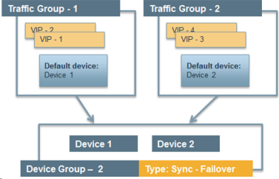
This illustration shows an example of the device group that this implementation creates, named Device Group A. This device group contains two BIG-IP devices, Device 1 and Device 2.
The configuration shows two traffic groups, traffic-group-1 and traffic-group-2, each containing failover objects. For traffic-group-1, Device 1 is the default device. For traffic-group-2, Device 2 is the default device. If Device 1 becomes unavailable, traffic-group-1 floats to Device 2. If Device 2 becomes unavailable, traffic-group-2 floats to Device 1.
By implementing this configuration, you ensure that:
- Each device has base network components configured.
- Any objects on a BIG-IP device that you configure for synchronization remain synchronized between the two devices.
- Failover capability and connection mirroring are enabled on each device.
Important: For active-active configurations, you must enable network failover instead of hard-wired serial failover.
Using the Setup utility, you can activate the license and provision the BIG-IP system.
-
From a workstation attached to the network on which you configured the management interface, type the following URL syntax where
<management_IP_address>is the address you configured for device management:https://<management_IP_address> -
At the login prompt, type the default user name
admin, and passwordadmin, and click Log in.The Setup utility screen opens.
-
Click Next.
-
Click Activate.
The License screen opens.
-
In the Base Registration Key field, paste the registration key.
-
Click Next and follow the process for licensing and provisioning the system.
Note: When you perform the licensing task so that you can run the F5 cloud ADC, you can accept the default provisioning values.
-
Click Next.
This displays the screen for configuring general properties and user administration settings.
The BIG-IP system license is now activated, and the relevant BIG-IP modules are provisioned.
Import or verify the certificate for the BIG-IP device.
-
Do one of the following:
- Click Import, import a certificate, click Import, and then click Next.
- Verify the displayed information for the certificate and click Next.
Configure the management port, time zone, and the administrative user names and passwords.
-
On the screen for configuring general properties, for the Management Port Configuration setting, select Manual.
-
For the Management Port 1 setting, specify an IP address, network mask, and default gateway.
You can leave the Management Port 2 setting blank.
-
In the Host Name field, type a fully-qualified domain name (FQDN) for the system.
The FQDN can consist of letters, numbers, and/or the characters underscore ( _ ), dash ( - ), or period ( . ).
-
For the Host IP Address setting, retain the default value Use Management Port IP Address.
-
From the Time Zone list, select a time zone.
The time zone you select typically reflects the location of the F5 system.
-
For the Root Account setting, type and confirm a password for the
rootaccount.The
rootaccount provides console access only. -
For the Admin Account setting, type and confirm a password.
Typing a password for the
adminaccount causes the system to terminate the login session. When this happens, log in to the F5 Configuration utility again, using the new password. The system returns to the appropriate screen in the Setup utility. -
For the SSH Access setting, select or clear the check box.
-
Click Next.
-
In the Standard Network Configuration area of the screen, click Next.
This displays the screen for enabling configuration synchronization and high availability.
When you perform this task, you set up config sync and connection mirroring, and you can specify the failover method (network, serial, or both).
-
For the Config Sync setting, select the Display configuration synchronization options check box.
This causes an additional ConfigSync screen to be displayed later.
-
For the High Availability setting, select the Display failover and mirroring options check box.
This displays the Failover Method list and causes additional failover screens to be displayed later.
-
From the Failover Method list, select Network and serial cable.
If you have a VIPRION system, select Network.
-
Click Next.
This displays the screen for configuring the default VLAN internal.
You can use the Setup utility to specify self IP addresses and settings for a VLAN on the BIG-IP internal network. The default VLAN for the internal network is named internal.
-
Specify the Self IP setting for the internal network:
-
In the Address field, type a self IP address.
-
In the Netmask field, type a network mask for the self IP address.
-
For the Port Lockdown setting, retain the default value.
-
-
Specify the Floating IP setting:
-
In the Address field, type a floating IP address.
This address should be distinct from the address you type for the Self IP setting.
Important: If the BIG-IP device you are configuring is accessed using Amazon Web Services and the device needs to failover to a device group peer, use the second, Secondary Private IP address for the floating IP address.
-
For the Port Lockdown setting, retain the default value.
-
-
For the VLAN Tag ID setting, retain the default value, auto.
This is the recommended value.
-
For the Interfaces setting:
-
From the Interface list, select an interface number.
-
From the Tagging list, select Tagged or Untagged.
Select Tagged when you want traffic for that interface to be tagged with a VLAN ID.
-
Click Add.
-
-
Click Next.
This completes the configuration of the internal self IP addresses and VLAN, and displays the screen for configuring the default VLAN external.
You can use the Setup utility to specify self IP addresses and settings for a VLAN on the BIG-IP external network. The default VLAN for the external network is named external.
-
Specify the Self IP setting for the external network:
-
In the Address field, type a self IP address.
-
In the Netmask field, type a network mask for the self IP address.
-
For the Port Lockdown setting, retain the default value.
-
-
In the Default Gateway field, type the IP address that you want to use as the default gateway to VLAN external.
-
Specify the Floating IP setting:
-
In the Address field, type a floating IP address.
This address should be distinct from the address you type for the Self IP setting.
Important: If the BIG-IP device you are configuring is accessed using Amazon Web Services and the device needs to failover to a device group peer, use the second, Secondary Private IP address for the floating IP address.
-
For the Port Lockdown setting, retain the default value.
-
-
For the VLAN Tag ID setting, retain the default value, auto.
This is the recommended value.
-
For the Interfaces setting:
-
From the Interface list, select an interface number.
-
From the Tagging list, select Tagged or Untagged.
Select Tagged when you want traffic for that interface to be tagged with a VLAN ID.
-
Click Add.
-
-
Click Next.
This completes the configuration of the external self IP addresses and VLAN, and displays the screen for configuring the default VLAN HA.
To configure a network for high availability, specify self IP addresses and settings for VLAN HA, which is the VLAN that the system will use for failover and connection mirroring.
-
For the High Availability VLAN setting, retain the default value, Create VLAN HA.
-
Specify the Self IP setting for VLAN HA:
-
In the Address field, type a self IP address.
-
In the Netmask field, type a network mask for the self IP address.
-
-
For the VLAN Tag ID setting, retain the default value, auto.
This is the recommended value.
-
For the Interfaces setting,
-
From the Interface list, select an interface number.
-
From the Tagging list, select Untagged.
-
Click Add.
-
-
Click Next.
This configures the self IP address and VLAN that the system will use for high availability and displays the default IP address that the system will use for configuration synchronization.
Use this task to specify the address that you want the system to use for configuration synchronization.
-
From the Local Address list, select a self IP address.
Do not select a management IP address.
-
Click Next.
This displays the screen for configuring unicast and multicast failover addresses.
Follow these task steps to specify the unicast IP addresses of the local device that you want the system to use for failover. Typically, you specify the self IP address for the local VLAN HA, as well as the IP address for the management port of the local device. If you are configuring a VIPRION system, configure a multicast failover address as well.
Important: When configuring failover and mirroring IP addresses, you select addresses of the local device only. Later, during the process of device discovery, the two devices in the device group discover each other’s addresses.
-
Locate the Failover Unicast Configuration area of the screen.
-
Under Local Address, confirm that there are entries for the self IP addresses that are assigned to the HA and internal VLANs and for the local management IP address for this device. If these entries are absent, click the Add button to add the missing entries to the list of Failover Unicast Addresses.
-
For the Address setting, select the address for the VLAN you need to add (either
HAorinternal). -
In the Port field, type a port number or retain the default port number,
1026. -
Click Repeat to add additional self IP addresses, or click Finished.
-
Repeat these steps to add a management IP address.
-
-
Click Next.
-
From the Primary Local Mirror Address list, retain the default value, which is the self IP address for VLAN
HA. -
From the Secondary Local Mirror Address list, select the address for VLAN
internal. -
Click Finished.
This causes you to leave the Setup utility.
Before you begin this task, verify that:
- Each BIG-IP device that is to be part of the local trust domain has a device certificate installed on it.
- The local device is designated as a certificate signing authority.
You perform this task to establish trust among devices on one or more network segments. Devices that trust each other constitute the local trust domain. A device must be a member of the local trust domain prior to joining a device group.
By default, the BIG-IP software includes a local trust domain with one member, which is the local device. You can choose any one of the BIG-IP devices slated for a device group and log into that device to add other devices to the local trust domain. For example, devices Bigip_1, Bigip_2, and Bigip_3 each initially shows only itself as a member of the local trust domain. To configure the local trust domain to include all three devices, you can simply log into device Bigip_1 and add devices Bigip_2 and Bigip_3 to the local trust domain; there is no need to repeat this process on devices Bigip_2 and Bigip_3.
-
On the Main tab, click Device Management > Device Trust > Device Trust Members.
-
Click Add.
-
From the Device Type list, select Peer or Subordinate.
-
Type a device IP address, administrator user name, and administrator password for the remote BIG-IP device with which you want to establish trust. The IP address you specify depends on the type of BIG-IP device:
- If the BIG-IP device is an appliance, type a management IP address (IPv4 or IPv6) for the device.
- If the BIG-IP device is a VIPRION device that is not licensed and provisioned for vCMP, type a primary cluster management IP address (IPv4 or IPv6) for the cluster.
- If the BIG-IP device is a VIPRION device that is licensed and provisioned for vCMP, then type a cluster management IP address (IPv4 or IPv6) for the guest.
- If the BIG-IP device is an Amazon Web Services EC2 device, type one of the Private IP addresses created for this EC2 instance.
-
Click Retrieve Device Information.
-
Verify that the certificate of the remote device is correct, and then click Device Certificate Matches.
-
In the Name field, verify that the name of the remote device is correct.
-
Click Add Device.
After you perform this task, the local device is now a member of the local trust domain. Also, the BIG-IP system automatically creates a special Sync-Only device group for the purpose of synchronizing trust information among the devices in the local trust domain, on an ongoing basis.
Repeat this task to specify each device that you want to add to the local trust domain.
This task establishes failover capability between two or more BIG-IP devices. If an active device in a Sync-Failover device group becomes unavailable, the configuration objects fail over to another member of the device group and traffic processing is unaffected. You perform this task on any one of the authority devices within the local trust domain.
Repeat this task for each Sync-Failover device group that you want to create for your network configuration.
-
On the Main tab, click Device Management > Device Groups.
-
On the Device Groups list screen, click Create.
The New Device Group screen opens.
-
In the Name field, type a name for the device group.
-
From the Group Type list, select Sync-Failover.
-
In the Description field, type a description of the device group.
This setting is optional.
-
From the Configuration list, select Advanced.
-
For the Members setting, select a host name from the Available list for each BIG-IP device that you want to include in the device group, including the local device. Use the Move button to move the host name to the Includes list.
The Available list shows any devices that are members of the device’s local trust domain but not currently members of a Sync-Failover device group. A device can be a member of one Sync-Failover group only. Also, for vCMP-provisioned systems on platforms that contain a hardware security module (HSM) supporting FIPS multi-tenancy, the FIPS partitions on the guests in the device group must be identical with respect to the number of SSL cores allocated to the guest’s FIPS partition and the maximum number of private SSL keys that the guest can store on the HSM.
-
From the Sync Type list:
- Select Automatic with Incremental Sync when you want the BIG-IP system to automatically sync the most recent BIG-IP configuration changes from a device to the other members of the device group. In this case, the BIG-IP system syncs the configuration data whenever the data changes on any device in the device group.
- Select Manual with Incremental Sync when you want to manually initiate a config sync operation. In this case, the BIG-IP system syncs the latest BIG-IP configuration changes from the device you choose to the other members of the device group. We strongly recommend that you perform a config sync operation whenever configuration data changes on one of the devices in the device group.
- Select Manual with Full Sync when you want to manually initiate a config sync operation. In this case, the BIG-IP system syncs the full set of BIG-IP configuration data from the device you choose to the other members of the device group. We strongly recommend that you perform a config sync operation whenever configuration data changes on one of the devices in the device group.
-
In the Maximum Incremental Sync Size (KB) field, retain the default value of
1024, or type a different value.This value specifies the total size of configuration changes that can reside in the incremental sync cache. If the total size of the configuration changes in the cache exceeds the specified value, the BIG-IP system performs a full sync whenever the next config sync operation occurs.
-
For the Network Failover setting, select or clear the check box:
- Select the check box if you want device group members to handle failover communications by way of network connectivity. This is the default value and is required for active-active configurations.
- Clear the check box if you want device group members to handle failover communications by way of serial cable (hard-wired) connectivity. For active-active configurations, you must select network failover, as opposed to serial-cable (hard-wired) connectivity.
-
In the Link Down Time on Failover field, use the default value of
0.0, or specify a new value.This setting specifies the amount of time, in seconds, that interfaces for any external VLANs are down when a traffic group fails over and goes to the standby state. Specifying a value other than
0.0for this setting causes other vendor switches to use the specified time to learn the MAC address of the newly-active device.Important: This setting is a system-wide setting, and does not apply to this device group only. Specifying a value in this field causes the BIG-IP system to assign this value to the global bigdb variable failover.standby.linkdowntime.
-
Click Finished.
Use this procedure to create a set of related configuration objects on the system (that is, an application).
-
On the Main tab, click iApp > Application Services.
-
Click Create.
-
In the Name field, type the name for your application service.
-
From the Template list, select a template.
-
From the Template Selection list, select Advanced.
This causes additional settings to appear.
-
For the
Configure Sync and/or Failover for this application?setting, select Yes. -
For the
Traffic Groupsetting, ensure that the Inherit traffic group from current partition / path field and traffic-group-1 are selected. -
Configure remaining settings as needed.
-
At the bottom of the screen click Finished to save your changes.
You now have an iApp application service, which is associated with the traffic group assigned to the root folder, traffic-group-1.
If you intend to specify a MAC masquerade address when creating a traffic group, you must first create the address, using an industry-standard method for creating a locally-administered MAC address.
Perform this procedure to create a traffic group to run on the remote BIG-IP device. You create this traffic group on the local device. Later, you move the traffic group to the remote device by forcing this traffic group on the local device to a standby state.
-
On the Main tab, click Device Management > Traffic Groups.
-
On the lower half of the screen, verify that the list shows the default floating traffic group (
traffic-group-1) for the local device. -
On the Traffic Groups screen, click Create.
-
Type the name
traffic-group-2for the new traffic group. -
Type a description of the new traffic group.
-
Click Next.
-
In the MAC Masquerade Address field, type a MAC masquerade address.
When you specify a MAC masquerade address, you reduce the risk of dropped connections when failover occurs. This setting is optional.
-
Click Next.
-
Select or clear the check box Always Failback to First Device if it is Available:
- Select the check box to cause the traffic group, after failover, to fail back to the first device in the traffic group’s ordered list when that device (and only that device) is available. If that device is unavailable, no failback occurs and the traffic group continues to run on the current device.
- Clear the check box to cause the traffic group, after failover, to remain active on its current device until failover occurs again.
-
Click Next.
-
Make sure that the displayed traffic group settings are correct.
-
Click Finished.
You now have a floating traffic group for which the default device is the peer device.
Use this procedure when you want to create an application to run on a remote device and associate it with the traffic group named traffic-group-2 that you previously created.
-
On the Main tab, click iApp > Application Services.
-
Click Create.
-
From the Template list, select a template.
-
From the Template Selection list, select Advanced.
This causes additional settings to appear.
-
In the Name field, type the name for your application service.
-
For the
Configure Sync and/or Failover for this application?setting, select Yes. -
For the
Traffic Groupsetting, clear the Inherit traffic group from current partition / path field and from the list, select traffic-group-2. -
Configure remaining settings as needed.
-
At the bottom of the screen click Finished to save your changes.
You now have an iApp application associated with traffic-group-2.
You perform this task when you want the selected traffic group on the local device to fail over to another device (that is, switch to a Standby state). Users typically perform this task when no automated method is configured for a traffic group, such as auto-failback or an HA group. By forcing the traffic group into a Standby state, the traffic group becomes active on another device in the device group. For device groups with more than two members, you can choose the specific device to which the traffic group fails over.
-
Log in to the device on which the traffic group is currently active.
-
On the Main tab, click Device Management > Traffic Groups.
-
In the Name column, locate the name of the traffic group that you want to run on the peer device.
-
Select the check box to the left of the traffic group name.
If the check box is unavailable, the traffic group is not active on the device to which you are currently logged in. Perform this task on the device on which the traffic group is active.
-
Click Force to Standby.
This displays target device options.
-
Choose one of these actions:
- If the device group has two members only, click Force to Standby. This displays the list of traffic groups for the device group and causes the local device to appear in the Next Active Device column.
- If the device group has more than two members, then from the Target Device list, select a value and click Force to Standby.
The selected traffic group is now in a standby state on the local device and active on another device in the device group.
Before you sync the configuration, verify that the devices targeted for config sync are members of a device group and that device trust is established.
This task synchronizes the BIG-IP configuration data from the local device to the devices in the device group. This synchronization ensures that devices in the device group operate properly. When synchronizing self IP addresses, the BIG-IP system synchronizes floating self IP addresses only.
Important: You perform this task on either of the two devices, but not both.
-
On the Main tab, click Device Management > Overview.
-
In the Device Groups area of the screen, click the arrow next to the name of the relevant device group.
The screen expands to show a summary and details of the sync status of the selected device group, as well as a list of the individual devices within the device group.
-
In the Devices area of the screen, choose the device that shows a sync status of
Changes Pending. -
In the Sync Options area of the screen, select Push the selected device configuration to the group.
-
Click Sync.
The BIG-IP system syncs the configuration data of the selected device to the other members of the device group.