Updated Date: 07/07/2026
Introduction to BIG-IP Service Function Chaining
A service function chain (SFC) defines an ordered set of abstract service functions and ordering constraints. These service functions and constraints are applied to packets, frames, and/or flows, as a result of traffic-flow classification.
A service chain deployment contains these logical components:
- Service Classifier Function (SCF)
- A node responsible for matching traffic flows against policies, specifying the chain, and inserting the Network Service Header (NSH) encapsulation.
- Service Function Forwarder (SFF)
- A node responsible for forwarding traffic to one or more connected service functions, according to information carried in the NSH encapsulation. An SFF also handles traffic coming back from a service function.
- Service Function (SF)
- A function responsible for specific treatment of received packets.
The current service function deployment models are relatively static, coupled to network topology and physical resources. This greatly reduces or eliminates the ability of an operator to introduce new services or dynamically create service function chains.
In the traditional operation, adding or removing a service function requires the network administrator to change the underlying network topology. Changing the topology:
- Causes downtime
- Is prone to errors
- Results in a topology that is still static
For example, consider a service provider that provides these two services to customers:
- Unlimited 4G LTE data plan
- Parental control
Here is a network topology that provides the unlimited data plan service and parental control service, but without SFC.
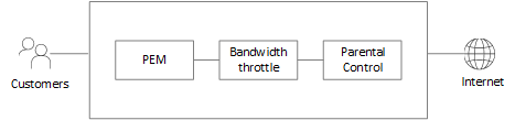
All customer traffic passes through BIG-IP Policy Enforcement Manager (PEM), followed by the node that throttles bandwidth and applies parental control before hitting the internet.
This topology has drawbacks:
- Traffic passes through all nodes, whether the service is purchased or not by the customer.
- Each service node must identify the customer and the services purchased, whether the service is to be applied or not. This results in redundant work for the service node.
- Even when the service is not applied, system resources are still consumed.
This image depicts a network topology that provides the unlimited data plan service and parental control service, but includes SFC.
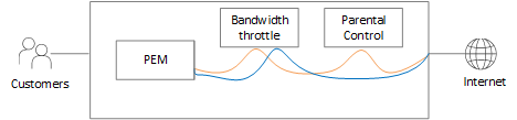
- The orange line denotes the traffic flow for customers who purchased parental control only.
- The blue line denotes the traffic flow for customers who didn’t purchase any service (the parental control or the unlimited data plan).
SFC ensures that each flow is subjected to only the services purchased for that flow.