Updated Date: 07/07/2026
Configuring an EtherIP Tunnel
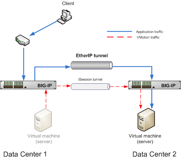
In some network configurations, the BIG-IP® system is configured to send application traffic to destination servers that are implemented as VMware® virtual machines (VMs). These VMs can undergo live migration, using VMware vMotion, across a wide area network (WAN) to a host in another data center. Optionally, an iSession® tunnel could provide WAN optimization.
To preserve any existing connections between the BIG-IP system and a virtual machine while the virtual machine migrates to another data center, you can create an EtherIP tunnel.
An EtherIP tunnel is an object that you create on each of two BIG-IP systems that sit on either side of a WAN. The EtherIP tunnel uses the industry-standard EtherIP protocol to tunnel Ethernet and IEEE 802.3 media access control (MAC) frames across an IP network. The two EtherIP tunnel objects together form a tunnel that logically connects two data centers. When the application traffic that flows between one of the BIG-IP systems and the VM is routed through the EtherIP tunnel, connections are preserved during and after the VM migration.
After you have configured the BIG-IP system to preserve connections to migrating VMs, you can create a Virtual Location monitor for the pool. A Virtual Location monitor ensures that the BIG-IP system sends connections to a local pool member rather than a remote pool one, when some of the pool members have migrated to a remote data center.
Tip: The BIG-IP system that is located on each end of an EtherIP tunnel can be part of a redundant system configuration. Make sure that both units of any redundant system configuration reside on the same side of the tunnel.
Implement an EtherIP tunneling configuration to prevent the system from dropping existing connections to migrating virtual machines in a VMware VMotion environment.
Important: Perform these tasks on the BIG-IP system in both the local data center and the remote data center.
VLANs represent a logical collection of hosts that can share network resources, regardless of their physical location on the network. You create a VLAN to associate physical interfaces with that VLAN.
-
On the Main tab, click Network > VLANs.
The VLAN List screen opens.
-
Click Create.
The New VLAN screen opens.
-
In the Name field, type a unique name for the VLAN.
-
In the Tag field, type a numeric tag, between 1-4094, for the VLAN, or leave the field blank if you want the BIG-IP system to automatically assign a VLAN tag.
The VLAN tag identifies the traffic from hosts in the associated VLAN.
-
If you want to use Q-in-Q (double) tagging, use the Customer Tag setting to perform the following two steps. If you do not see the Customer Tag setting, your hardware platform does not support Q-in-Q tagging and you can skip this step.
-
From the Customer Tag list, select Specify.
-
Type a numeric tag, from 1-4094, for the VLAN.
The customer tag specifies the inner tag of any frame passing through the VLAN.
-
-
For the Interfaces setting,
-
From the Interface list, select an interface number.
-
From the Tagging list, select Untagged.
-
Click Add.
-
-
For the Hardware SYN Cookie setting, select or clear the check box.
When you enable this setting, the BIG-IP system triggers hardware SYN cookie protection for this VLAN.
Enabling this setting causes additional settings to appear. These settings appear on specific BIG-IP platforms only.
-
For the Syncache Threshold setting, retain the default value or change it to suit your needs.
The Syncache Threshold value represents the number of outstanding SYN flood packets on the VLAN that will trigger the hardware SYN cookie protection feature.
When the Hardware SYN Cookie setting is enabled, the BIG-IP system triggers SYN cookie protection in either of these cases, whichever occurs first:
- The number of TCP half-open connections defined in the LTM setting Global SYN Check Threshold is reached.
- The number of SYN flood packets defined in this Syncache Threshold setting is reached.
-
For the SYN Flood Rate Limit setting, retain the default value or change it to suit your needs.
The SYN Flood Rate Limit value represents the maximum number of SYN flood packets per second received on this VLAN before the BIG-IP system triggers hardware SYN cookie protection for the VLAN.
-
Click Finished.
The screen refreshes, and it displays the new VLAN in the list.
Before you perform this task, you must know the self IP address of the instance of the VLAN that exists, or will exist, on the BIG-IP system in the other data center.
The purpose of an EtherIP tunnel that contains an EtherIP type of profile is to enable the BIG-IP system to preserve any current connections to a server that is using VMware vMotion for migration to another data center.
-
On the Main tab, click Network > Tunnels > Tunnel List > Create.
The New Tunnel screen opens.
-
In the Name field, type a unique name for the tunnel.
-
From the Profile list, select etherip.
-
In the Local Address field, type the self IP address of the local BIG-IP system.
-
In the Remote Address field, type the self IP address of the remote BIG-IP system.
-
If the BIG-IP system is part of an HA cluster, select the corresponding traffic group from the Traffic Group list.
-
Click Finished.
VLAN groups consolidate Layer 2 traffic from two or more separate VLANs.
-
On the Main tab, click Network > VLANs > VLAN Groups.
The VLAN Groups list screen opens.
-
From the VLAN Groups menu, choose List.
-
Click Create.
The New VLAN Group screen opens.
-
In the General Properties area, in the VLAN Group field, type a unique name for the VLAN group.
-
For the VLANs setting, from the Available field select the internal and external VLAN names, and click << to move the VLAN names to the Members field.
-
Click Finished.
Ensure that you have at least one VLAN configured before you create a self IP address.
Self IP addresses enable the BIG-IP system, and other devices on the network, to route application traffic through the associated VLAN.
-
On the Main tab, click Network > Self IPs.
-
Click Create.
The New Self IP screen opens.
-
In the Name field, type a unique name for the self IP address.
-
In the IP Address field, type an IPv4 or IPv6 address.
This IP address should represent the address space of the VLAN that you specify with the VLAN/Tunnel setting.
-
In the Netmask field, type the network mask for the specified IP address.
For example, you can type
255.255.255.0. -
From the VLAN/Tunnel list, select the VLAN to associate with this self IP address.
- On the internal network, select the internal or high availability VLAN that is associated with an internal interface or trunk.
- On the external network, select the external VLAN that is associated with an external interface or trunk.
-
Use the default values for all remaining settings.
-
Click Finished.
The screen refreshes, and displays the new self IP address.
The BIG-IP system can now send and receive TCP/IP traffic through the specified VLAN.
Before you create a self IP address, ensure that you have created at least one VLAN or VLAN group.
A self IP address enables the BIG-IP system and other devices on the network to route application traffic through the associated VLAN or VLAN group.
-
On the Main tab, click Network > Self IPs.
-
Click Create.
The New Self IP screen opens.
-
In the IP Address field, type a self IP address for the VLAN group. In the example shown, this IP address is 10.0.0.6.
-
In the Netmask field, type the network mask for the specified IP address.
For example, you can type
255.255.255.0. -
From the VLAN/Tunnel list, select the name of the VLAN group you previously created.
-
From the Port Lockdown list, select Allow Default.
-
Click Finished.
The screen refreshes, and displays the new self IP address.
The BIG-IP system can send and receive traffic through the specified VLAN or VLAN group.
When the BIG-IP system is directing application traffic to pool members that are implemented as virtual machines, you should configure a Virtual Location type of monitor on the BIG-IP system. A Virtual Location monitor determines if a pool member is local to the data center or remote, and assigns a priority group to the pool member accordingly. The monitor assigns remote pool members a lower priority than local members, thus ensuring that the BIG-IP directs application requests to local pool members whenever possible.
-
On the Main tab, click Local Traffic > Monitors.
The Monitors List screen opens.
-
Click Create.
The New Monitor screen opens.
-
Type
my_virtual_location_monitorin the Name field. -
From the Type list, select Virtual Location.
-
From the Configuration list, select Advanced.
-
Retain the default value (in seconds) of
5in the Interval field. -
Retain the default value of
Disabledin the Up Interval list. -
Retain the default value (in seconds) of
0in the Time Until Up field. -
Retain the default value (in seconds) of
16in the Timeout field. -
Type the name of the pool that you created prior to configuring EtherIP tunneling in the Pool Name field.
-
Click Finished.
After configuring the Virtual Location monitor, the BIG-IP system assigns each member of the designated pool a priority group value to ensure that incoming connections are directed to a local pool member whenever possible.
F5 Networks recommends that you verify that BIG-IP DNS has automatically assigned a BIG-IP type of monitor to BIG-IP Local Traffic Manager (LTM). A BIG-IP type of monitor can use the priority group assigned to each pool member to retrieve a gtm_score value.
Before you sync the configuration, verify that the devices targeted for config sync are members of a device group and that device trust is established.
This task synchronizes the BIG-IP configuration data from the local device to the devices in the device group. This synchronization ensures that devices in the device group operate properly. When synchronizing self IP addresses, the BIG-IP system synchronizes floating self IP addresses only.
Important: You perform this task on either of the two devices, but not both.
-
On the Main tab, click Device Management > Overview.
-
In the Device Groups area of the screen, click the arrow next to the name of the relevant device group.
The screen expands to show a summary and details of the sync status of the selected device group, as well as a list of the individual devices within the device group.
-
In the Devices area of the screen, choose the device that shows a sync status of
Changes Pending. -
In the Sync Options area of the screen, select Push the selected device configuration to the group.
-
Click Sync.
The BIG-IP system syncs the configuration data of the selected device to the other members of the device group.
After you configure EtherIP tunneling on the BIG-IP system, you must perform the same configuration procedure on the BIG-IP system in the remote data center to fully establish the EtherIP tunnel.
After the tunnel is established, the BIG-IP system preserves any open connections to migrating (or migrated) virtual machine servers.