Updated Date: 07/07/2026
Configuring Network Virtualization Tunnels
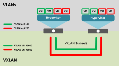
Large data centers and cloud service providers are benefiting from large scale network virtualization. Network Virtualization provides connectivity in cloud environments by overlaying Layer 2 segments over a Layer 3 infrastructure. The overlay network can be dynamically extended with multiple virtualized networks without affecting the Layer 3 infrastructure. This number of virtualized networks is typically much larger than the number of VLANS the infrastructure can support.
You can configure a BIG-IP® system to function as a gateway in a virtualized network, bridging the data center virtualized networks with the physical network (L2 gateway), or performing routing and higher L4-L7 functionality among virtual networks of different types (L3 gateway). Connecting these networks allows for expansion, and provides a mechanism to streamline the transition of data centers into a virtualized model, while maintaining connectivity.
This illustration shows the BIG-IP system as a network virtualization gateway.
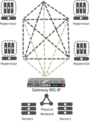
In a virtualized network, the BIG-IP system needs to learn about other virtualization tunnel endpoints. Each hypervisor has a tunnel endpoint. The hypervisor needs to locate the virtual machines it manages, by maintaining a form of the L2 location records, typically, IP addresses and MAC addresses, virtual network identifiers, and virtual tunnel endpoints.
When you configure a BIG-IP® system as a network virtualization gateway, the system represents the connection as a tunnel, which provides a Layer 2 interface on the virtual network. You can use the tunnel interface in both Layer 2 and Layer 3 configurations. After you create the network virtualization tunnels, you can use the tunnels like you use VLANs on a BIG-IP system, such as for routing, assigning self IP addresses, and associating with virtual servers.
Creating a network virtualization tunnel on a BIG-IP system provides an L2 gateway to connect the physical underlay network with a virtual overlay network.
-
On the Main tab, click Network > Tunnels > Tunnel List > Create or Carrier Grade NAT > Tunnels > Create.
The New Tunnel screen opens.
-
In the Name field, type a unique name for the tunnel.
-
From the Profile list, select the tunnel profile you created for network virtualization.
This selection must be a profile based on either the
greorvxlanparent profile, depending on your virtualized network environment. -
In the Local Address field, type the self IP address of the VLAN through which the remote hypervisor is reachable.
-
For the Remote Address list, retain the default selection, Any.
-
In the Key field, type the VNI (Virtual Network Identifier) to use for a VXLAN tunnel or the Virtual Subnet Identifier (VSID) to use for a NVGRE tunnel.
This field appears above the Profile field when you select a profile that requires this setting.
-
Click Finished.
This tunnel is now available to use in virtualized network routing configurations, depending on how you configure your network.
These terms are associated with virtualized networks.
- forwarding database (FDB)
- The FDB is the database that contains mappings between the MAC address of each virtual machine and the IP address of the hypervisor machine on which it resides.
- L2 gateway
- The Layer 2 gateway performs the bridge functionality between VLAN and virtual segments in a virtualized network.
- L3 gateway
- The Layer 3 gateway performs routing and higher L4-L7 functionality among virtualized network segments of different types.
- overlay network
- The overlay network is a virtual network of VMs built on top of a stable L2-L3 structure. The view from one VM to another is as if they were on the same switch, but, in fact, they could be far afield.
- tunnel endpoint
- A tunnel endpoint originates or terminates a tunnel. In a virtualized network environment, the tunnel IP addresses are part of the L2 underlay network. The same local IP address can be used for multiple tunnels.
- underlay network
- The underlay network is the L2 or L3 routed physical network, a mesh of tunnels.
- virtualized network
- A virtualized network is when you create a virtual L2 or L3 topology on top of a stable physical L2 or L3 network. Connectivity in the virtual topology is provided by tunneling Ethernet frames in IP over the physical network.
- VNI
- The Virtual Network Identifier (VNI) is also called the VXLAN segment ID. The system uses the VNI to identify the appropriate tunnel.
- VSID
- The Virtual Subnet Identifier (VSID) is a 24-bit identifier used in an NVGRE environment that represents a virtual L2 broadcast domain, enabling routes to be configured between virtual subnets.
- VTEP
- The VXLAN Tunnel Endpoint (VTEP) originates or terminates a VXLAN tunnel. The same local IP address can be used for multiple tunnels.
- VXLAN
- Virtual eXtended LAN (VXLAN) is a network virtualization scheme that overlays Layer 2 over Layer 3. VLXAN uses Layer 3 multicast to support the transmission of multicast and broadcast traffic in the virtual network, while decoupling the virtualized network from the physical infrastructure.
- VXLAN gateway
- A VXLAN gateway bridges traffic between VXLAN and non-VXLAN environments. The BIG-IP® system uses a VXLAN gateway to bridge a traditional VLAN and a VXLAN network, by becoming a network virtualization endpoint.
- VXLAN header
- In addition to the UDP header, encapsulated packets include a VXLAN header, which carries a 24-bit VNI to uniquely identify Layer 2 segments within the overlay.
- VXLAN segment
- A VXLAN segment is a Layer 2 overlay network over which VMs communicate. Only VMs within the same VXLAN segment can communicate with each other.
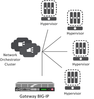
Using the BIG-IP® system as a network virtualization gateway, you can set up virtualized network segments using either a centralized or decentralized model.
In a centralized model, a network orchestrator or controller manages the virtualized network segments. The orchestrator has full view of VTEPs, L2, and L3 information in the overlay, and is responsible for pushing this information to hypervisors and gateways. Microsoft Hyper-V and VMware NSX environments use this model.
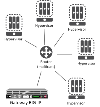
A decentralized model of network virtualization does not require a network orchestrator or controller. In this model, the router learns the tunnel endpoint and MAC address locations by flooding broadcast, multicast, and unknown destination frames over IP multicast. VMware vSphere 5.1 environments use this model.
The BIG-IP® system supports multiple network virtualization tunnel types. You can even combine virtualized network segments based on different tunnel types. This table offers a quick comparison of the tunnel types.
| VXLAN (Multicast) | VXLAN (Unicast) | NVGRE | Transparent Ethernet Bridging |
|---|---|---|---|
| Decentralized | Centralized | Centralized | Centralized |
| VMware vSphere 5.1 | VMware NSX | Microsoft SCVMM/Hyper-V | OpenStack |
| VXLAN UDP Encapsulation | VXLAN UDP Encapsulation | GRE-based Encapsulation | GRE-based Encapsulation |
| 24-bit ID | 24-bit ID | 24-bit ID | 32-bit ID |
| Endpoints discovered dynamically | Endpoints statically configured | Endpoints statically configured | Endpoints statically configured |
| Floods unknown and broadcast frames using IP multicast. | Can flood using unicast replication. | Does not flood (completely static). | Floods using unicast replication. |
In addition to the above types of tunnels, the BIG-IP system supports the creation of Geneve Network Virtualization tunnels. Like VXLAN, Geneve tunnels support multicast and multipoint flooding.
Note: IPv4 multicast addresses in the local network control block (224.0.0/24) [RFC 5771] should not be used for configuring the remote address of the VXLAN/Geneve tunnels with multicast flooding.
For the centralized model, you can use VXLAN (Unicast), NVGRE, or Transparent Ethernet Bridging, depending on the cloud environment. Using an agent or plug-in, or the tmsh command-line utility, you can statically configure the FDB and ARP forwarding table entries. Using the tmsh command-line utility or browser interface, you can create the network virtualization tunnels, which are managed by the network controller.
As you configure a BIG-IP® system to be an L2 or L3 gateway for statically configured network virtualization tunnels, keep these considerations in mind.
- The BIG-IP system must be licensed for SDN Services.
- If you have over 2000 tunnels, set the Management (MGMT) setting on the Resource Provisioning screen is to Large (System > Resource Provisioning).
Using the tmsh command-line utility, you can add static FDB records and ARP entries for each virtual tunnel endpoint.
-
Add static FDB (forwarding database) entries to associate MAC addresses with specified tunnel endpoints. For example, the following command creates an FDB entry that associates the MAC address
00:01:02:03:04:05with the tunnel endpoint10.1.1.1of the tunnelvxlan0.# tmsh modify net fdb tunnel vxlan0 records add { 00:01:02:03:04:05 { endpoint 10.1.1.1 } } -
Delete a MAC address from an FDB entry.
# tmsh modify net fdb tunnel vxlan0 records delete { 00:01:02:03:04:05 } -
Delete a static ARP.
# tmsh delete net arp 10.3.3.1 -
Add an IP address to a MAC address in the ARP table.
# tmsh create net arp 10.3.3.1 { ip-address 10.3.3.1 mac-address 00:01:02:03:04:05 }
Using the iControl/REST API, you can program a network controller to build and maintain network virtualization tunnels. This example adds an entry to the FDB table that associates the MAC address 00:01:02:03:04:05 with the tunnel endpoint 10.1.1.2 of the tunnel vxlan0-tunnel.
$ curl -u admin:f5site02 -H "Content-Type:=application/json" -k -X PUT
'https://172.30.69.69/mgmt/tm/net/fdb/tunnel/~Common~vxlan0-tunnel' -d
'{"kind":"tm:net:fdb:tunnel:tunnelstate","name":"vxlan0-tunnel","partition":"Common",
"fullPath":"/Common/vxlan0-tunnel","generation":1,
"selfLink":"https://localhost/mgmt/tm/net/fdb/tunnel/~Common~vxlan0-tunnel?
ver=11.5.0","records":[{"name":"00:01:02:03:04:05",
"endpoint":"10.1.1.2"}]}'  |python -m json.tool
{
    "fullPath": "/Common/vxlan0-tunnel",
    "generation": 1,
    "kind": "tm:net:fdb:tunnel:tunnelstate",
    "name": "vxlan0-tunnel",
    "partition": "Common",
    "records": [
        {
            "endpoint": "10.1.1.2",
            "name": "00:01:02:03:04:05"
        }
    ],
    "selfLink": "https://localhost/mgmt/tm/net/fdb/tunnel/~Common~vxlan0-tunnel?ver=11.5.0"
}
You can use the tunnel forwarding database (FDB) record type known as endpoints to configure a set of remote endpoints. The remote endpoints are used to send unknown destination, multicast, and broadcast frames. The MAC address for any endpoints record must be ff:ff:ff:ff:ff:ff.
The following commands show how to use the Traffic Management Shell (tmsh) to create and delete a record of endpoints.
Create a record of endpoints:
tmsh modify net fdb tunnel *tunnel\_name* records add { ff:ff:ff:ff:ff:ff { endpoints add { *IP\_addresses* } } }
Delete a record of endpoints:
tmsh modify net fdb tunnel *tunnel\_name* records delete { ff:ff:ff:ff:ff:ff }
This listing example illustrates the steps for creating a routing configuration that includes an NVGRE tunnel on the BIG-IP® system. F5 Networks provides an API for you to configure the F5 SCVMM Gateway Provider plug-in to build and manage NVGRE tunnels.
create net vlan wan {
    interfaces add { 1.1 }
    mtu 1550
}
create net self 10.1.1.1/24 {
    address 10.1.1.1/24
    vlan wan
}
create net tunnels gre nvgre {
    encapsulation nvgre
}
create net tunnels tunnel nvgre5000 {
    local-address 10.1.1.1
    remote-address any
    profile nvgre
    key 5000
}
create net vlan legacy5000 {
    interfaces add { 2.1 }
}
create net route-domain 5000 {
    id 5000
    vlans add { nvgre5000 legacy5000 }
}
create net self 10.3.3.1%5000/24 {
    address 10.3.3.1%5000/24
    vlan nvgre5000
}
create net self 10.4.4.1%5000/24 {
    address 10.4.4.1%5000/24
    vlan legacy5000
}
create net route 10.5.5.0%5000/24 {
    network 10.5.5.0%5000/24
    gw 10.3.3.2%5000
}
create net route 10.6.6.0%5000/24 {
    network 10.6.6.0%5000/24
    gw 10.3.3.3%5000
}
modify net fdb tunnel nvgre5000 {
    records add {
        00:FF:0A:03:03:02 { endpoint 10.1.1.2 }
        00:FF:0A:03:03:03 { endpoint 10.1.1.3 }
    }
}
create net arp 10.3.3.2%5000 {
    mac-address 00:FF:0A:03:03:02
}
create net arp 10.3.3.3%5000 {
    mac-address 00:FF:0A:03:03:03
} This example listing illustrates the steps for creating a routing configuration that includes a VXLAN tunnel on the BIG-IP® system. This configuration adds the tunnel to a route domain. You can use the iControl/REST API to configure a network controller to build and manage VXLAN (unicast) tunnels.
create net vlan wan {
    interfaces add { 1.1 }
    mtu 1550
}
create net self 10.1.1.1/24 {
    address 10.1.1.1/24
    vlan wan
}
create net tunnels vxlan vxlan-static {
    flooding-type none
}
create net tunnels tunnel vxlan5000 {
    local-address 10.1.1.1
    remote-address any
    profile vxlan-static
    key 5000
}
create net vlan legacy5000 {
    interfaces add { 2.1 }
}
create net route-domain 5000 {
    id 5000
    vlans add {vxlan5000 legacy5000 }
}
create net self 10.3.3.1%5000/24 {
    address 10.3.3.1%5000/24
    vlan vxlan5000
}
create net self 10.4.4.1%5000/24 {
    address 10.4.4.1%5000/24
    vlan legacy5000
}
create net route 10.5.5.0%5000/24 {
    network 10.5.5.0%5000/24
    gw 10.3.3.2%5000
}
create net route 10.6.6.0%5000/24 {
    network 10.6.6.0%5000/24
    gw 10.3.3.3%5000
}
modify net fdb tunnel vxlan5000 {
    records add {
        00:FF:0A:03:03:02 { endpoint 10.1.1.2 }
        00:FF:0A:03:03:03 { endpoint 10.1.1.3 }
    }
}
create net arp 10.3.3.2%5000 {
    mac-address 00:FF:0A:03:03:02
}
create net arp 10.3.3.3%5000 {
    mac-address 00:FF:0A:03:03:03
}An alternative for including a network virtualization tunnel in a routing configuration is to create a virtual server that listens for the tunnel traffic, such as in the following example.
# tmsh create ltm virtual http_virtual destination 10.3.3.15%5000:http ip-protocol tcp vlans add { vxlan5000 }The code in this example creates a virtual server http_virtual that listens for traffic destined for the IP address 10.3.3.15 on the tunnel named vxlan5000.
You can use the tmsh command-line utility to view tunnel statistics, listing either all the tunnels on the BIG-IP® system or statistics about a particular tunnel.
View per-tunnel statistics:
# tmsh show net tunnels tunnelView static and dynamic FDB entries:
# tmsh show net fdb tunnelIn a VMware vSphere 5.1 environment, you can configure VXLAN without knowing all the remote tunnel endpoints. The BIG-IP® system uses multicast flooding to learn unknown and broadcast frames. VXLAN can extend the virtual network across a set of hypervisors, providing L2 connectivity among the hosted virtual machines (VMs). Each hypervisor represents a VXLAN tunnel endpoint (VTEP). In this environment, you can configure a BIG-IP system as an L2 VXLAN gateway device to terminate the VXLAN tunnel and forward traffic to and from a physical network.
You can configure Virtual eXtended LAN (VXLAN) on a BIG-IP® system to enable a physical VLAN to communicate with virtual machines (VMs) in a virtual network.
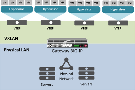
When you configure a BIG-IP system as an L2 VXLAN gateway, the BIG-IP system joins the configured multicast group, and can forward both unicast and multicast or broadcast frames on the virtual network. The BIG-IP system learns about MAC address and VTEP associations dynamically, thus avoiding unnecessary transmission of multicast traffic.
As you configure VXLAN on a BIG-IP® system, keep these considerations in mind.
- If you configure the BIG-IP device as a bridge between physical VLANs and a VXLAN tunnel, the number of virtualized network segments in the overlay is limited to the maximum number of physical VLANs (4094). This limitation does not apply to Layer 3 configurations.
- You need to configure a separate tunnel for each VNI. The tunnels can have the same local and remote endpoint addresses.
- For the Layer 2 network, you must ensure a loop-free topology.
- Do not modify the configuration of a VXLAN tunnel after it is created. Instead, delete the existing tunnel and create a new one.
You perform this task when you want to use an existing VLAN with a VXLAN tunnel that disaggregates traffic based on the inner header of the packet (hardware-disaggregated or DAG tunnel).
-
On the Main tab, click Network > VLANs.
The VLAN List screen opens.
-
In the Name column, click the relevant VLAN name.
This displays the properties of the VLAN.
-
From the DAG tunnel list, select Inner.
This disaggregates encapsulated packets based on the inner headers.
-
Click Finished.
Before you configure VXLAN, ensure that these conditions are met:
- The system must be licensed for SDN Services.
- Network connectivity exists between the BIG-IP system and the hypervisors.
- If you have over 2000 tunnels, the Management (MGMT) setting on the Resource Provisioning screen is set to Large (System > Resource Provisioning).
Before you perform this task, confirm that you have enabled the DAG Tunnel setting on the relevant VLAN.
When you enable the DAG tunnel feature on a VLAN, you must also configure a bigdb variable that specifies a port number so that associated tunnels can disaggregate based on the inner header of a packet.
-
Open the TMOS Shell (
tmsh).tmsh -
Specify a port number to be used.
modify sys db iptunnel.vxlan.udpport value <port_number>
The value that you specify with this
bigdbvariable applies to all VLANs on which the DAG Tunnel setting is enabled.Important: Typically, a tunnel uses port 4789. If you choose to use a different port number, you must ensure that the port number specified in the relevant VXLAN profile matches the value you set with this command.
Creating a VXLAN multicast tunnel on a BIG-IP system provides an L2 VXLAN gateway to connect the physical network with a virtualized network.
-
On the Main tab, click Network > Tunnels > Tunnel List > Create or Carrier Grade NAT > Tunnels > Create.
The New Tunnel screen opens.
-
In the Name field, type a unique name for the tunnel.
-
From the Profile list, select vxlan.
This setting tells the system which tunnel profile to use. The system-supplied VXLAN profile specifies port
4789. To change the port number, you can create a new VXLAN profile, which then appears in this list. -
In the Local Address field, type the self IP address of the VLAN through which the remote hypervisor is reachable.
-
In the Remote Address field, type the multicast group address associated with the VXLAN segment.
-
For the Mode list, retain the default selection, Bidirectional.
-
In the MTU field, type the maximum transmission unit of the tunnel.
The default value is 0. The valid range is from 0 to 65515.
-
For the Use PMTU (Path MTU) setting, select or clear the check box.
- If enabled and the tunnel MTU is set to 0, the tunnel will use the PMTU information.
- If enabled and the tunnel MTU is fixed to a non-zero value, the tunnel will use the minimum of PMTU and MTU.
- If disabled, the tunnel will use fixed MTU or calculate its MTU using tunnel encapsulation configurations .
-
From the TOS list, select Preserve, or select Specify and type a Type of Service (TOS) value.
The valid range is from 0 to 255.
-
From the Auto-Last Hop list, select a value.
- Choose Default if you want the system to use the global Auto Last Hop setting (if enabled).
- Choose Enabled if you want this setting to take precedence over the global Auto Last Hop setting, for this tunnel only.
- Choose Disabled if you want to disable auto last hop behavior for this tunnel only.
-
From the Traffic Group list, select the traffic group that includes the local IP address for the tunnel.
-
Click Finished.
Before you begin this task, verify that a VXLAN multicast tunnel exists on the BIG-IP system.
You can create a VLAN group to bridge the traffic between a VXLAN overlay network (Layer 3) and a non-VXLAN (Layer 2) network.
-
On the Main tab, click Network > VLANs > VLAN Groups.
The VLAN Groups list screen opens.
-
Click Create.
The New VLAN Group screen opens.
-
In the Name field, type a unique name for the VLAN group.
-
For the VLANs setting, select the VLAN that connects to the non-VXLAN Layer-2 network and the VXLAN tunnel you created, and using the Move button (<<), move your selections from the Available list to the Members list.
-
Click Finished.
By default, the BIG-IP system synchronizes all existing tunnel objects in its config sync operation. This operation requires that the local IP address of a tunnel be set to a floating self IP address. In a high availabilty (HA) configuration, any tunnel with a floating local IP address would be available only on the active device, which would prevent some features, such as health monitors, from using the tunnel on the standby device. To make a tunnel available on both the active and standby devices, you need to set the local IP address to a non-floating self IP address, which then requires that you exclude tunnels from the config sync operation. To disable the synchronization of tunnel objects, you can set a bigdb variable on both devices.
In certain cases, you might want to disable config sync behavior for tunnels, such as when you need to make VXLAN tunnels functional on all devices in a BIG-IP device group configured for high availability. The tunnel config sync setting applies to all tunnels created on the BIG-IP device.
Important: Disable config sync on both the active and standby devices before you create any tunnels.
-
Log in to the
tmshcommand-line utility for the BIG-IP system. -
Determine whether the variable is already disabled, by typing this command.
tmsh list sys db iptunnel.configsync value -
Disable the variable.
tmsh modify sys db iptunnel.configsync value disable -
Save the configuration.
tmsh save sys config -
F5 recommends that you reboot both the active and standby devices.
Now you can create tunnels with non-floating local IP addresses on both the active and standby devices.
The BIG-IP system can create and delete VXLAN tunnels in an overlay segment using the Open vSwitch Database (OVSDB) management protocol. The system does this by communicating with a software-defined networking (SDN) controller that supports OVSDB.
The BIG-IP OVSDB management component includes support for the Bidirectional Forwarding Detection protocol (BFD). With this protocol, the system can detect the failure of an active service node and remove the node from the hash algorithm that is used for forwarding broadcast packets.
For certain SDN controllers, you can use an orchestration plug-in to manage the creation and deletion of the VXLAN tunnels.
Once the plug-in creates the tunnel object, the OVSDB BIG-IP component creates and maintains any necessary L2 and L3 objects as directed by the SDN controller.
You can configure the BIG-IP system’s OVSDB management component, using the BIG-IP Configuration utility. With this component, the system can communicate with one or more OVSDB-capable software-defined networking (SDN) controllers to receive information for configuring VXLAN tunnel endpoints in an overlay segment.
-
On the Main tab, click System > Configuration > OVSDB.
-
From the OVSDB list, select Enable.
-
In the Controller Addresses field, type an OVSDB-capable controller IP address, and click Add.
Controller addresses can be in either IPv4 or IPv6 format. If you specify IPv6 addresses, confirm that an IPv6 management address is also configured on the BIG-IP system.
If the BIG-IP system is communicating with a controller cluster, repeat this step for each controller IP address.
-
From the Flooding Type list, select the flooding mechanism to be used to process unknown frames.
|
Replicator |
When you select this option, the BIG-IP system uses the default VXLAN profile |
|
Multipoint |
When you select this option, the BIG-IP system uses the default VXLAN profile |
- From the Logical Routing Type list, select whether you want the BIG-IP system to use logical routing.
|
None |
Select this option if no logical routing is to be used. |
|
Backhaul |
Select this option to use backhaul logical routing.Note: Before you can use backhaul logical routing, you must enable the BIG-IP system DB variable |
-
In the Port field, type the controller’s port or retain the default.
-
In the Tunnel Local Address field, type the IP address of the local endpoint of the tunnel.
The OVSDB management component uses this setting to configure the non-floating local address of the tunnels. This value can be either an IPv4 or IPv6 address.
-
If the BIG-IP device is a member of a Device Service Cluster (DSC) Sync-Failover device group and the tunnels need to have a floating address, then for the Tunnel Floating Addresses setting, in the Available box, select , one or more floating self IP addresses and move the addresses to the Selected box.
Note: The SDN controller uses the DSC traffic groups that contain the selected self IP addresses to populate physical switch records in the OVSDB database. The Tunnel Floating Addresses setting appears only on devices that are in DSC configurations.
-
For the Tunnel Maintenance Mode, select whether you want the BIG-IP system to create VXLAN tunnels automatically.
|
Active |
The BIG-IP system creates VXLAN tunnels automatically. |
|
Passive |
An orchestration plug-in is responsible for maintaining the VXLAN tunnel objects in the BIG-IP system. The OVSDB component will still maintain the necessary Layer 2 and Layer 3 objects as directed by the SDN controller. |
-
From the Log Level list, select the level of detail you want to display in the log file used for troubleshooting,
/var/tmp/vxland.out. -
Configure the SSL certificate settings:
-
From the Certificate File list, select a certificate file to be presented to the controller.
-
From the Certificate Key File list, select the certificate key file that has the private key.
-
From the CA Certificate File list, select the CA certificate file.
This is the file containing the CA certificate used to validate the certificates presented by the controller.
-
-
From the Bidirectional Forwarding Detection list, select Enable or Disable.
If you select Enable, the Route Domain setting appears.
-
If you chose Enable in the previous step, then from the Route Domain list, select the name of a route domain.
To use this setting, you must have at least one route domain defined on the system in addition to route domain
0. -
Click Update.
You can configure a VXLAN Generic Protocol Extension (GPE) tunnel when you want to add fields to the VXLAN header. One of these fields is Next Protocol, with values for Ethernet, IPv4, IPv6, and Network Service Header (NSH).
Creating a VXLAN Generic Protocol Extension (GPE) multicast tunnel on a BIG-IP system provides an L2 VXLAN gateway to connect the physical network with a virtualized network. Unlike a standard VXLAN tunnel, this tunnel type supports the processing of VXLAN GPE-encapsulated Ethernet frames.
-
On the Main tab, click Network > Tunnels > Tunnel List > Create or Carrier Grade NAT > Tunnels > Create.
The New Tunnel screen opens.
-
In the Name field, type a unique name for the tunnel.
-
From the Profile list, select vxlan-gpe.
This setting tells the system which tunnel profile to use. The system-supplied
vxlan-gpeprofile specifies port4790. To change the port number, you can create a new VXLAN-GPE profile, which then appears in this list. -
In the Local Address field, type the self IP address of the VLAN through which the remote hypervisor is reachable.
-
In the Remote Address field, select Any, or select Specify and type the multicast group address associated with the VXLAN-GPE segment.
-
For the Mode list, retain the default selection, Bidirectional.
-
In the MTU field, type the maximum transmission unit of the tunnel.
The default value is 0. The valid range is from 0 to 65515.
-
For the Use PMTU (Path MTU) setting, select or clear the check box.
- If enabled and the tunnel MTU is set to 0, the tunnel will use the PMTU information.
- If enabled and the tunnel MTU is fixed to a non-zero value, the tunnel will use the minimum of PMTU and MTU.
- If disabled, the tunnel will use fixed MTU or calculate its MTU using tunnel encapsulation configurations .
-
From the TOS list, select Preserve, or select Specify and type a Type of Service (TOS) value.
The valid range is from 0 to 255.
-
From the Auto-Last Hop list, select a value.
- Choose Default if you want the system to use the global Auto Last Hop setting (if enabled).
- Choose Enabled if you want this setting to take precedence over the global Auto Last Hop setting, for this tunnel only.
- Choose Disabled if you want to disable auto last hop behavior for this tunnel only.
-
From the Traffic Group list, select the traffic group that includes the local IP address for the tunnel.
-
Click Finished.