Updated Date: 07/07/2026
Configuring NVGRE Tunnels for HA-Paired Devices
You can set up Network Virtualization using Generic Routing Encapsulation (NVGRE) tunnels on an HA pair of BIG-IP® devices. For NVGRE, you are creating a tunnel interface that can process packets to and from both floating and non-floating self IP addresses. The Local Address field specifies the floating tunnel IP address, and the Secondary Address field specifies the non-floating tunnel IP address. Monitor traffic uses the non-floating tunnel IP address, while forwarded traffic uses the floating tunnel IP address.
When you specify a secondary address, ConfigSync is disabled for the tunnel.
After you configure the NVGRE tunnel, two sets of NVGRE flows are created. The floating tunnel IP address is the source of one set of flows, and the non-floating tunnel IP address is the source of the other set. The NVGRE flows that originate from the floating tunnel IP address are available only on the active device.
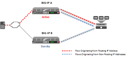
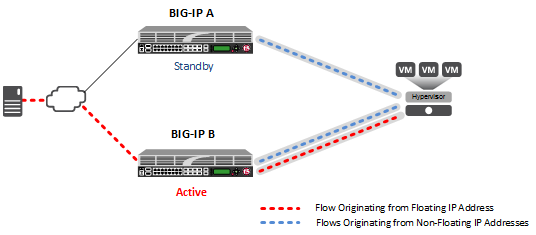
After failover, the forwarded traffic flows through the tunnel associated with the floating IP address, which is now active on the other device. Monitor traffic continues to flow through the tunnels associated with the non-floating IP addresses.
The Microsoft Hyper-V uses customer records to represent the associations of overlay addresses with remote tunnel endpoints. This information needs to be statically configured for each overlay address:
- Customer IP address (overlay address)
- Customer MAC address
- Provider IP address (underlay/tunnel endpoint)
- VSID (tunnel key)
- Routing domain
One example of overlay addresses is self IP addresses assigned to NVGRE tunnel objects on the BIG-IP system. If an address is configured as a floating self IP address, the tunnel local endpoint must also be a floating self IP address. This ensures that failover maintains the validity of the Hyper-V configuration. The traffic groups used for the overlay self IP addresses also need to be configured with a masquerading MAC address.
In an HA configuration, the config sync operation applies, by default, to all tunnel objects on all devices, regardless of whether the tunnel local endpoints are set to floating self IP addresses. This behavior restricts NVGRE tunnels to using only floating self IP addresses, unless you specify a secondary address when you create the tunnel.
The way you create an NVGRE tunnel for a pair of BIG-IP devices in an HA configuration makes the tunnel available for both forwarded and monitor traffic.
-
On the Main tab, click Network > Tunnels > Tunnel List > Create or Carrier Grade NAT > Tunnels > Create.
The New Tunnel screen opens.
-
In the Name field, type a unique name for the tunnel.
-
From the Profile list, select nvgre.
This setting tells the system which tunnel profile to use. The system-supplied NVGRE profile is adequate. To change the settings, you can create a new NVGRE profile, which then appears in this list.
-
In the Key field, type the Virtual Subnet Identifier (VSID) to use for the NVGRE tunnel.
This field appears above the Profile field when you select a profile that requires this setting.
-
In the Local Address field, type the local endpoint IP address.
This should be a floating self IP address.
-
In the Secondary Address field, select Specify, and type the non-floating local IP address of the tunnel, for use with locally initiated traffic, such as monitor traffic.
-
For the Remote Address list, retain the default selection, Any.
-
For the Mode list, retain the default selection, Bidirectional.
-
In the MTU field, type the maximum transmission unit of the tunnel.
The default value is 0. The valid range is from 0 to 65515.
-
For the Use PMTU (Path MTU) setting, select or clear the check box.
- If enabled and the tunnel MTU is set to 0, the tunnel will use the PMTU information.
- If enabled and the tunnel MTU is fixed to a non-zero value, the tunnel will use the minimum of PMTU and MTU.
- If disabled, the tunnel will use fixed MTU or calculate its MTU using tunnel encapsulation configurations .
-
From the TOS list, select Preserve, or select Specify and type a Type of Service (TOS) value.
The valid range is from 0 to 255.
-
From the Auto-Last Hop list, select a value.
- Choose Default if you want the system to use the global Auto Last Hop setting (if enabled).
- Choose Enabled if you want this setting to take precedence over the global Auto Last Hop setting, for this tunnel only.
- Choose Disabled if you want to disable auto last hop behavior for this tunnel only.
-
From the Traffic Group list, select the traffic group that includes the local IP address for the tunnel.
-
Click Finished.