Updated Date: 07/07/2026
Setting Up IPsec To Use NAT Traversal on One Side of the WAN
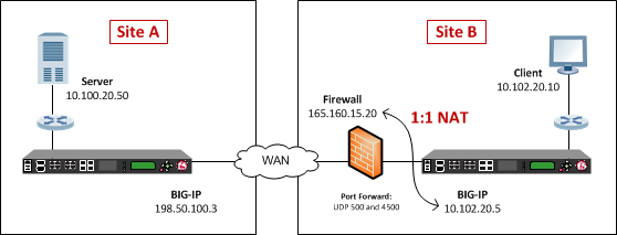
When you are using IPsec to secure WAN traffic, you can set up an IPsec tunnel with NAT traversal (NAT-T) to get around a firewall or other NAT device. This implementation describes how to set up the IPsec tunnel when you have a NAT device on one side of the tunnel.
The following illustration shows a network configuration with a firewall (NAT device) on one side of the WAN.
Before you configure IPsec on a BIG-IP® device, make sure that you have completed the following general prerequisites.
- You must have an existing routed IP network between the two locations where the BIG-IP devices will be installed.
- The BIG-IP hardware is installed with an initial network configuration applied.
- The management IP address is configured on the BIG-IP system.
- If you are using NAT traversal, forward UDP ports 500 and 4500 to the BIG-IP system behind each firewall.
- Verify the connectivity between the client or server and its BIG-IP device, and between each BIG-IP device and its gateway. You can use
pingto test connectivity.
When you are configuring an IPsec tunnel, you must repeat the configuration tasks on the BIG-IP systems on both sides of the WAN.
For IPsec, you create a forwarding (IP) type of virtual server to intercept IP traffic and direct it over the tunnel. With a forwarding (IP) virtual server, destination address translation and port translation are disabled.
-
On the Main tab, click Local Traffic > Virtual Servers.
The Virtual Server List screen opens.
-
Click Create.
The New Virtual Server screen opens.
-
In the Name field, type a unique name for the virtual server.
-
From the Type list, select Forwarding (IP).
-
In the Destination Address/Mask field, type a wildcard network address in CIDR format, such as
0.0.0.0/0for IPv4 or::/0for IPv6, to accept any traffic. -
From the Service Port list, select *All Ports.
-
From the Protocol list, select *All Protocols.
-
From the VLAN and Tunnel Traffic list, retain the default selection, All VLANs and Tunnels.
-
Click Finished.
You can create an IPsec tunnel to securely transport application traffic across the WAN. You must configure an IPsec tunnel on the BIG-IP systems on both sides of the WAN.
When you create an IKEv1 or IKEv2 peer for NAT traversal (NAT-T), the key configuration detail is that the Remote Address setting you configure on the BIG-IP system behind the firewall or other NAT device is the public IP address of the NAT device (not the IP address of the remote BIG-IP system). You can customize the remaining settings to conform to your network.
Important: For the IKE peer negotiations to be successful, the IKE Phase 1 settings (on the IKE peer) and IKE Phase 2 settings (in the IPsec policy) must be the same on the BIG-IP systems at both ends of the IPsec tunnel.
Important: You must perform this procedure twice, once on each BIG-IP system on either side of the WAN. For each step in the procedure where you need to type an IP address, the step shows two sample IP addresses – one that you configure on the BIG-IP system located in Site A and the other that you configure on the BIG-IP system located in Site B.
-
Create an IKE peer that specifies the other end of the IPsec tunnel.
-
On the Main tab, click Network > IPsec > IKE Peers.
-
Click the Create button.
-
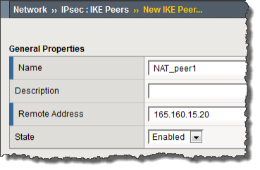
In the Name field, type a unique name for the IKE peer.
-
In the Remote Address field, type the IP address of the remote peer.
If the remote BIG-IP system is behind a firewall or other NAT device, type the public IP address of that device.
If the remote BIG-IP system is reachable directly, type the IP address of the BIG-IP system.
Note: This address must match the value of the Tunnel Remote Address of the remote site setting in the relevant IPsec policy.
For example, on Site A, you specify the translation address for the BIG-IP system in Site B. The BIG-IP system in Site B is behind the NAT device. Here are the peer remote addresses that you would configure on the BIG-IP systems in Site A and Site B, according to the previous illustration.
Location Remote (Peer) Address Site A 165.160.15.20Site B 198.50.100.3This screen snippet shows the peer Remote Address setting at Site A.
-
For the IKE Phase 1 Algorithms area, retain the default values, or select the options that are appropriate for your deployment.
-
For the IKE Phase 1 Credentials area, for the Authentication Method setting, select either Preshared Key or RSA Signature, and specify additional information in the fields that appear.
For example, if you select Preshared Key, type the key in the Preshared Key field that becomes available.
In this example, Preshared Key is selected.
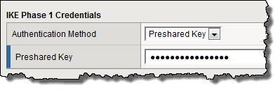
Note: The key you type must be the same at both ends of the tunnel.
-
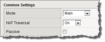
From the NAT Traversal list, select On, for Site A’s IKE peer only.
Note: Use this setting only for the IKE peer (remote BIG-IP system) that is behind a NAT device. On the Site B BIG-IP system, for the IKE peer, retain the default setting, Off.
-
Click Finished.
-
-
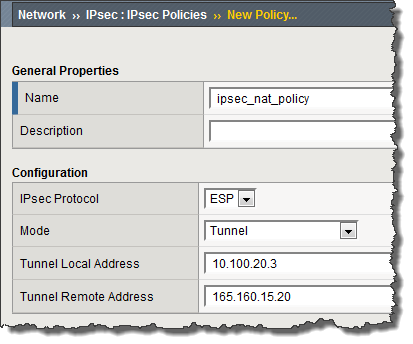
Create a custom IPsec policy that uses Tunnel mode and has the same remote IP address as the IKE peer.
-
On the Main tab, click Network > IPsec > IPsec Policies.
-
Click the Create button.
-
In the Name field, type a unique name for the policy.
-
For the IPsec Protocol setting, retain the default selection, ESP.
-
From the Mode list, select Tunnel.
The screen refreshes to show additional related settings.
-
In the Tunnel Local Address field, type the local IP address of the system you are configuring.
For example, the tunnel local addresses that you configure on the BIG-IP systems in Site A and Site B are as follows.
Location Tunnel Local Address Site A 198.50.100.3Site B 10.102.20.5 -
In the Tunnel Remote Address field, type the IP address of the remote peer.
If the remote BIG-IP system is behind a NAT device, type the public IP address of that device.
If the remote BIG-IP system is reachable directly, type the IP address of the remote BIG-IP system.
Note: This address must match the value of the Remote Address setting in the relevant IKE peer.
Based on the sample configuration in the implementation overview, the tunnel remote addresses that you configure on the BIG-IP systems in Site A and Site B are as follows.
Location Tunnel Remote Address Site A 165.160.15.20Site B 198.50.100.3This screen snippet shows the tunnel settings at Site A.
-
For the Authentication Algorithm setting, retain the default value, or select the algorithm appropriate for your deployment.
-
For the Encryption Algorithm setting, retain the default value, or select the algorithm appropriate for your deployment.
-
For the Perfect Forward Secrecy setting, retain the default value, or select the option appropriate for your deployment.
-
Click Finished.
-
-
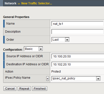
Create a bidirectional traffic selector that uses the custom IPsec policy you created.
The traffic selector filters the application traffic based on the source and destination IP addresses you specify.
-
On the Main tab, click Network > IPsec > Traffic Selectors.
-
Click Create.
-
In the Name field, type a unique name for the traffic selector.
-
For the Order setting, retain the default value.
-
For the Source IP Address setting, in the Address field, type the IP address from which the application traffic originates.
In the illustration the source IP addresses that you configure on the BIG-IP systems in Site A and Site B are as follows.
Location Source IP Address Site A 10.100.20.50Site B 10.102.20.10 -
For the Destination IP Address setting, in the Address field, type the final IP address for which the application traffic is destined.
In the illustration, the destination IP addresses that you configure on the BIG-IP systems in Site A and Site B are as follows.
Location Destination IP Address Site A 10.102.20.10Site B 10.100.20.50 -
For the Action setting, retain the default value, Protect.
-
From the IPsec Policy Name list, select the name of the custom IPsec policy that you just created.
This screen snippet is an example of the completed Traffic Selector screen at Site A.
-
Click Finished.
-
-
Repeat this task on the BIG-IP system on the other side of the WAN.
After doing this task on each BIG-IP system in the configuration, you have created an IPsec tunnel through which traffic travels in both directions across the WAN, and through a firewall on one side.
After you have configured an IPsec tunnel and before you configure additional functionality, you can verify that the tunnel is passing traffic.
Note: Only data traffic matching the traffic selector triggers the establishment of the tunnel.
-
Access the
tmshcommand-line utility. -
Before sending traffic, type this command at the prompt.
tmsh modify net ipsec ike-daemon ikedaemon log-level debugThis command increases the logging level to display the messages that you want to view.
-
Send data traffic to the destination IP address specified in the traffic selector.
-
For an IKEv1 configuration, check the IKE Phase 1 negotiation status by typing this command at the prompt.
racoonctl -l show-sa isakmpThis example shows a result of the command.
Destinationis the tunnel remote IP address.Destination Cookies ST S V E Created Phase2 165.160.15.20.500 98993e6 . . . 22c87f1 9 I 10 M 2012-06-27 16:51:19 1This table shows the legend for interpreting the result.
Column Displayed Description ST (Tunnel Status) 1 Start Phase 1 negotiation 2 msg 1 received 3 msg 1 sent 4 msg 2 received 5 msg 2 sent 6 msg 3 received 7 msg 3 sent 8 msg 4 received 9 isakmp tunnel established 10 isakmp tunnel expired S I Initiator R Responder V (Version Number) 10 ISAKMP version 1.0 E (Exchange Mode) M Main (Identity Protection) A Aggressive Phase2 <n> Number of Phase 2 tunnels negotiated with this IKE peer -
For an IKEv1 configuration, check the IKE Phase 2 negotiation status by typing this command at the prompt.
racoonctl -ll show-sa internalThis example shows a result of this command.
Sourceis the tunnel local IP address.Destinationis the tunnel remote IP address.Source Destination Status Side 10.100.20.3 165.160.15.20 sa established [R]This table shows the legend for interpreting the result.
Column Displayed Side I (Initiator) R (Responder) Status init start acquire getspi sent getspi done 1st msg sent 1st msg recvd commit bit sa added sa established sa expired -
To verify the establishment of dynamic negotiated Security Associations (SAs), type this command at the prompt.
tmsh show net ipsec ipsec-saFor each tunnel, the output displays IP addresses for two IPsec SAs, one for each direction, as shown in the example.
IPsec::SecurityAssociations 10.100.20.3 -> 165.160.15.20 SPI(0x7b438626) in esp (tmm: 6) 165.160.15.20 -> 10.100.20.3 SPI(0x5e52a1db) out esp (tmm: 5) -
To display the details of the dynamic negotiated Security Associations (SAs), type this command at the prompt.
tmsh show net ipsec ipsec-sa all-propertiesFor each tunnel, the output displays the details for the IPsec SAs, as shown in the example.
IPsec::SecurityAssociations 165.160.15.20 -> 10.100.20.3 ----------------------------------------------------------------------------- tmm: 2 Direction: out; SPI: 0x6be3ff01(1810104065); ReqID: 0x9b0a(39690) Protocol: esp; Mode: tunnel; State: mature Authenticated Encryption : aes-gmac128 Current Usage: 307488 bytes Hard lifetime: 94 seconds; unlimited bytes Soft lifetime: 34 seconds; unlimited bytes Replay window size: 64 Last use: 12/13/2012:10:42 Create: 12/13/2012:10:39 -
To display the details of the IKE-negotiated SAs (IKEv2), type this command at the prompt.
tmsh show net ipsec ike-sa all-properties -
To filter the Security Associations (SAs) by traffic selector, type this command at the prompt.
tmsh show net ipsec ipsec-sa traffic-selector ts_codecYou can also filter by other parameters, such as SPI (
spi), source address (src_addr), or destination address (dst_addr)The output displays the IPsec SAs that area associated with the traffic selector specified, as shown in the example.
IPsec::SecurityAssociations 10.100.115.12 -> 10.100.15.132 SPI(0x2211c0a9) in esp (tmm: 0) 10.100.15.132 -> 10.100.115.12 SPI(0x932e0c44) out esp (tmm: 2) -
Check the IPsec stats by typing this command at the prompt.
tmsh show net ipsec-statIf traffic is passing through the IPsec tunnel, the stats will increment.
------------------------------------------------------------------- Net::Ipsec Cmd Id Mode Packets In Bytes In Packets Out Bytes Out ------------------------------------------------------------------- 0 TRANSPORT 0 0 0 0 0 TRANSPORT 0 0 0 0 0 TUNNEL 0 0 0 0 0 TUNNEL 0 0 0 0 1 TUNNEL 353.9K 252.4M 24.9K 1.8M 2 TUNNEL 117.9K 41.0M 163.3K 12.4M -
If the SAs are established, but traffic is not passing, type one of these commands at the prompt.
tmsh delete net ipsec ipsec-sa(IKEv1)tmsh delete net ipsec ike-sa(IKEv2)This action deletes the IPsec tunnels. Sending new traffic triggers SA negotiation and establishment.
-
If traffic is still not passing, type this command at the prompt.
racoonctl flush-sa isakmpThis action brings down the control channel. Sending new traffic triggers SA negotiation and establishment.
-
View the
/var/log/racoon.logto verify that the IPsec tunnel is up.These lines are examples of the messages you are looking for.
2012-06-29 16:45:13: INFO: ISAKMP-SA established 10.100.20.3[500]-165.160.15.20[500] spi:3840191bd045fa51:673828cf6adc5c61 2012-06-29 16:45:14: INFO: initiate new phase 2 negotiation: 10.100.20.3[500]<=>165.160.15.20[500] 2012-06-29 16:45:14: INFO: IPsec-SA established: ESP/Tunnel 165.160.15.20[0]->10.100.20.3[0] spi=2403416622(0x8f413a2e) 2012-06-29 16:45:14: INFO: IPsec-SA established: ESP/Tunnel 10.100.20.3[0]->165.160.15.20[0] spi=4573766(0x45ca46 -
To turn on IKEv2 logging on a production build, complete these steps.
Important: If you are using IKEv2, you can skip these steps; the BIG-IP system enables IPsec logging by default.
-
Configure the log publisher for IPsec to use.
% tmsh create sys log-config publisher ipsec { destinations add { local-syslog }} % tmsh list sys log-config publisher ipsec sys log-config publisher ipsec { destinations { local-syslog { } } } -
Attach the log publisher to the
ike-daemonobject.tmsh modify net ipsec ike-daemon ikedaemon log-publisher ipsec
-
-
For protocol-level troubleshooting, you can increase the debug level by typing this command at the prompt.
tmsh modify net ipsec ike-daemon ikedaemon log-level debug2Important: Use this command only for debugging. It creates a large log file, and can slow the tunnel negotiation.
Note: Using this command flushes existing SAs.
-
After you view the results, return the debug level to normal to avoid excessive logging by typing this command at the prompt.
tmsh modify net ipsec ike-daemon ikedaemon log-level infoNote: Using this command flushes existing SAs.