Updated Date: 07/07/2026
Installing a BIG-IP System Without Changing the IP Network
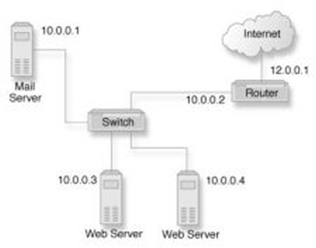
A combination of several features of the BIG-IPsystem makes it possible for you to place a BIG-IP system in a network without changing the existing IP network. The following illustration shows the data center topology before you add the BIG-IP system. The data center has one LAN, with one IP network, 10.0.0.0. The data center has one router to the Internet, two web servers, and a back-end mail server.
The existing data center structure does not support load balancing or high availability. The following illustration shows an example of the data center topology after you add the BIG-IP system.
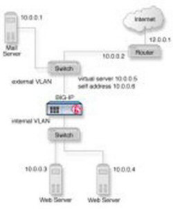
To configure the system for this implementation, you must perform a few key tasks. The example shown in the illustration is based on the use of the default internal and external VLAN configuration with self IP addresses on each of the VLANs that are on the same IP network on which you are installing the BIG-IP system.
Important: The default route on each content server should be set to the IP address of the router. In this example, you set the default route to 10.0.0.2.
Remove the self IP addresses from the individual VLANs. After you create the VLAN group, you will create another self IP address for the VLAN group for routing purposes. The individual VLANs no longer need their own self IP addresses.
-
On the Main tab, click Network > Self IPs.
-
Select the check box for each IP address and VLAN that you want to delete.
-
Click Delete.
-
Click Delete.
The self IP address is removed from the Self IP list.
VLAN groups consolidate Layer 2 traffic from two or more separate VLANs.
-
On the Main tab, click Network > VLANs > VLAN Groups.
The VLAN Groups list screen opens.
-
From the VLAN Groups menu, choose List.
-
Click Create.
The New VLAN Group screen opens.
-
In the General Properties area, in the VLAN Group field, type a unique name for the VLAN group.
-
For the VLANs setting, from the Available field select the internal and external VLAN names, and click << to move the VLAN names to the Members field.
-
Click Finished.
Before you create a self IP address, ensure that you have created at least one VLAN or VLAN group.
A self IP address enables the BIG-IP system and other devices on the network to route application traffic through the associated VLAN or VLAN group.
-
On the Main tab, click Network > Self IPs.
-
Click Create.
The New Self IP screen opens.
-
In the IP Address field, type a self IP address for the VLAN group. In the example shown, this IP address is 10.0.0.6.
-
In the Netmask field, type the network mask for the specified IP address.
For example, you can type
255.255.255.0. -
From the VLAN/Tunnel list, select the name of the VLAN group you previously created.
-
From the Port Lockdown list, select Allow Default.
-
Click Finished.
The screen refreshes, and displays the new self IP address.
The BIG-IP system can send and receive traffic through the specified VLAN or VLAN group.
You can a create pool of web servers that you group together to receive and process traffic, to efficiently distribute the load on your server resources.
-
On the Main tab, click Local Traffic > Pools.
The Pool List screen opens.
-
Click Create.
The New Pool screen opens.
-
In the Name field, type a unique name for the pool.
-
In the Resources area of the screen, use the New Members setting to add the pool members. In our example, pool members are 10.0.0.3:80 and 10.0.0.4:80.
-
Click Finished.
The load balancing pool appears in the Pools list.
A virtual server represents a destination IP address for application traffic.
-
On the Main tab, click Local Traffic > Virtual Servers.
The Virtual Server List screen opens.
-
Click Create.
The New Virtual Server screen opens.
-
In the Name field, type a unique name for the virtual server.
-
In the Destination Address/Mask field:
- If you want to specify a single IP address, confirm that the Host button is selected, and type the IP address in CIDR format.
- If you want to specify multiple IP addresses, select the Address List button, and confirm that the address list that you previously created appears in the box.
The supported format is address/prefix, where the prefix length is in bits. For example, an IPv4 address/prefix is
10.0.0.1or10.0.0.0/24, and an IPv6 address/prefix isffe1::0020/64or2001:ed8:77b5:2:10:10:100:42/64. When you use an IPv4 address without specifying a prefix, the BIG-IP system automatically uses a/32prefix.
Note: The IP address or addresses for this field must be on the same subnet as the external self-IP address.
-
From the Service Port list, select *All Ports.
-
In the Resources area of the screen, from the Default Pool list, select the relevant pool name.
You now have a destination IP address on the BIG-IP system for application traffic.