Updated Date: 07/07/2026
Deploying Stateless Network Address Translation
The 6rd (rapid deployment) feature is a solution to the IPv6 address transition. It provides a stateless protocol mechanism for tunneling IPv6 traffic from the IPv6 Internet over a service provider’s (SP’s) IPv4 network to the customer’s IPv6 networks. As specified in RFC5969, 6rd uses an SP’s own IPv6 address prefix rather than the well-known IPV6 in IPv4 prefix (2002::/16), which means that the operational domain of 6rd is limited to the SP network, and is under the SP’s control.
Fully compliant with RFC5969, the BIG-IP system supports the border relay (BR) functionality by automatically mapping the tunnel’s IPv4 address at the customer premises to IPv6 address spaces using the 6rd domain configuration information. Using a BIG-IP system, an SP can deploy a single 6rd domain or multiple 6rd domains. When supporting multiple 6rd domains, a separate tunnel is required to accommodate each 6rd domain, which is specified in the associated 6rd tunnel profile.
When you deploy 6rd using a BIG-IP system as the BR device, you need to create 6rd tunnels using wildcard remote addresses. This implementation documents the configuration of a BIG-IP device as a BR device.
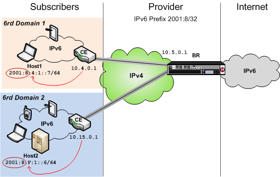
This table shows examples of 6rd parameter values, based on the illustration. You set these values in the v6rd profile you create.
| Setting | Value |
|---|---|
| IPv4 Prefix | 10 |
| IPv4 Prefix Length | 8 |
| IPv6 Prefix | 2001:8:4:1 |
| IPv6 Prefix Length | 64 |
You must create a new v6rd profile to specify the parameters for a 6rd tunnel. The system-supplied v6rd profile, v6rd provides the defaults, but does not suffice as a 6rd profile, as configured. For example, the required 6rd prefix is not specified.
-
On the Main tab, click Network > Tunnels > Profiles > v6rd > Create.
The New 6RD Profile screen opens.
-
In the Name field, type a unique name for the profile.
-
Select the Custom check box.
-
For the IPv4 Prefix setting, type the IPv4 prefix that is assumed to be the customer edge (CE) device’s IPv4 address, which is not included in the customer’s IPv6 6rd prefix. A value of
0.0.0.0indicates that all 32 bits of the CE’s IPv4 address are to be extracted from its 6rd IPv6 prefix.Note: If you do not provide an IPv4 prefix, the system derives it from the tunnel local address you specify when creating the tunnel.
-
For the IPv4 Prefix Length setting, type the number of identical high-order bits shared by all CE and BR IPv4 addresses in the 6rd domain you are configuring.
-
For the 6rd Prefix setting, type the IPv6 prefix for the 6rd domain you are configuring.
-
For the 6rd Prefix Length setting, type the length of the IPv6 prefix for the 6rd domain you are configuring.
-
Click Finished.
To apply this profile to traffic, you must associate it with a tunnel.
Before creating a 6rd tunnel on a BIG-IP system, you must have configured a v6rd tunnel profile.
You can create a 6rd tunnel on a BIG-IP system to carry IPv6 traffic over an IPv4 network, allowing your users to seamlessly access the IPv6 Internet.
-
On the Main tab, click Network > Tunnels > Tunnel List > Create or Carrier Grade NAT > Tunnels > Create.
The New Tunnel screen opens.
-
In the Name field, type a unique name for the tunnel.
-
From the Profile list, select v6rd.
-
In the Local Address field, type the IPv4 address of the BIG-IP device you are configuring.
-
For the Remote Address list, retain the default selection, Any.
-
Click Finished.
After you create the 6rd tunnel at the BR, you must configure your network routing to send remote traffic through the tunnel.
You can create a forwarding virtual server to intercept IP traffic and direct it to a tunnel.
-
On the Main tab, click Local Traffic > Virtual Servers.
The Virtual Server List screen opens.
-
Click Create.
The New Virtual Server screen opens.
-
In the Name field, type a unique name for the virtual server.
-
From the Type list, select Forwarding (IP).
-
In the Destination Address/Mask field, type
::/0to accept any IPv6 traffic. -
In the Service Port field, type
*or select * All Ports from the list. -
From the Protocol list, select * All Protocols.
-
Click Finished.
Now that you have created a virtual server to intercept the IP traffic, you need to create a route to direct this traffic to the tunnel interface.
Ensure that you have created an IP tunnel before starting this task.
Self IP addresses can enable the BIG-IP system, and other devices on the network, to route application traffic through the associated tunnel, similar to routing through VLANs and VLAN groups.
Note: If the other side of the tunnel needs to be reachable, make sure the self IP addresses that you assign to both sides of the tunnel are in the same subnet.
-
On the Main tab, click Network > Self IPs.
-
Click Create.
The New Self IP screen opens.
-
In the Name field, type a unique name for the self IP address.
-
In the IP Address field, type the IP address of the tunnel.
The system accepts IPv4 and IPv6 addresses.
Note: This is not the same as the IP address of the tunnel local endpoint.
-
In the Netmask field, type the network mask for the specified IP address.
For example, you can type
255.255.255.0. -
From the VLAN/Tunnel list, select the tunnel with which to associate this self IP address.
-
Click Finished.
The screen refreshes, and displays the new self IP address.
Assigning a self IP to a tunnel ensures that the tunnel appears as a resource for routing traffic.
To direct traffic through the tunnel, add a route for which you specify the tunnel as the resource.
Before starting this task, ensure that you have created a 6rd tunnel, and have assigned a self IP address to the tunnel.
You can route traffic through a tunnel interface, much like you use a VLAN or VLAN group.
-
On the Main tab, click Network > Routes.
-
Click Add.
The New Route screen opens.
-
In the Name field, type a unique user name.
This name can be any combination of alphanumeric characters, including an IP address.
-
In the Destination field, type the 6rd IPv6 network address.
-
In the Netmask field, type the network mask for the destination IP address.
-
From the Resource list, select Use VLAN/Tunnel.
-
From the VLAN/Tunnel list, select the name of the v6rd tunnel you created.
-
Click Finished.
Mapping of Address and Port (MAP) is an IPv4 to IPv6 transition technology. The BIG-IP system plays the role of the border relay (BR) in a MAP deployment. At the time of this writing, the implementation of MAP on the BIG-IP system complies with the IETF Standards Track draft Mapping of Address and Port with Encapsulation (MAP) draft-ietf-software-map-10.
Note: You must configure the customer edge (CE) functionality of the MAP solution on the CE device, not on the BIG-IP system.
This illustration shows the position of a BIG-IP system in a MAP configuration. As the BR device, the BIG-IP system decapsulates the encapsulated IPv6 traffic and forwards it to the public IPv4 Internet.
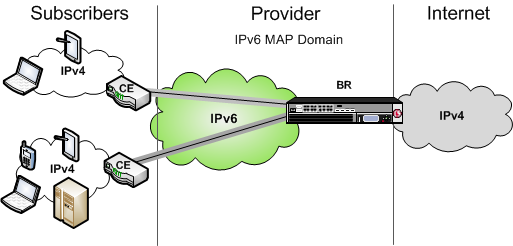
MAP is a deterministic algorithm that uses MAP-domain configuration information to map between IPv4 and IPv6 addresses to transport IPv4 traffic over the IPv6 infrastructure. MAP is nearly stateless, and it does not require the border relay (BR) device to perform NAT on the traffic. Instead, the translation of private to public IPv4 addresses is delegated to the customer edge (CE) devices, such as customer-premises equipment (CPEs). Mapping of Address and Port (MAP) uses a port mapping algorithm to provide IPv4 connectivity over an IPv6 network. The MAP implementation has two variants, which share the same architecture.
- MAP-E (Encapsulated), which uses the IPv4-in-IPv6 tunneling approach, is on the IETF standards track, and is now referred to as simply MAP.
- MAP-T (Translated), which uses the IPv4-from/to-IPv6 address translation approach, is on the IETF experimental track.
Both MAP and MAP-T assume that the service provider internal network has already been migrated to IPv6, but the CE is still running dual stack. IPv6 subscribers behind the CE can use regular addressing methods to reach the public IPv6 Internet. MAP focuses on how the CEs should forward IPv4 subscriber traffic to and from the Internet.
In a MAP-T deployment, the customer edge (CE) device implements a combination of stateful NAPT44 translation and stateless MAP translation, using a source IPv4 address and port number to forward IPv4 traffic across the upstream IPv6 network. The border relay (BR) is responsible for connecting one or more MAP domains to external IPv4 networks. It converts the inbound IPv6 packet from the CEs back to NAT’d IPv4, using the corresponding MAP configurations.
In a MAP (formerly MAP-E) deployment, the customer edge (CE) device implements a combination of NAPT44 followed by IPv4-in-IPv6 encapsulation. The source IPv6 address of the encapsulating header is derived from the source IPv4 address and port number, according to MAP configurations. At the border relay (BR), the IPv6 traffic is decapsulated to recover the NAT’d IPv4 packet, which the system then forwards to the Internet.
The MAP CE devices and BRs form a MAP domain. The MAP domain is defined by the algorithms and parameters for mapping IPv4 address and port numbers to a subscriber. All CE nodes within the same MAP domain must use the same subnet ID, as configured in the ip4-prefix attribute of the BR configuration, to correctly synthesize the MAP IPv6 address.
MAP relies on port sharing, which means that it supports only ICMP and port-based transport protocols. This excludes PPTP (which uses GRE) and any transports other than TCP, UDP, or ICMP. Because the port sharing ratio and IPv6 prefix are mathematically interdependent, you must correctly size your IPv6 network to ensure that your implementation of MAP accommodates enough subscribers.
The BR handles traffic between itself and a given MAP domain, which means that it has at least one IPv4 interface and one IPv6 interface. Its job is to aggregate the MAP tunnels. Within the MAP Domain, IPv4 traffic follows IPv6 routing, and the BR is reachable using IPv6 anycast addressing for load balancing and resiliency.
The port set ID (PSID) algorithmically represents different groups of non-overlapping, contiguous L4 ports that a CE device can use for port translation, allowing different CE devices to share the same source IPV4 address. As an anti-spoofing measure, the PSID is embedded within the IPv6 address for validation at the BR.
A MAP Domain encapsulates and decapsulates IPv4 traffic using a Basic Mapping Rule (BMR) specified in the MAP draft. The objective of a BMR is to provision a source IPv6 address that generates sets of source IPv4 translation endpoints. The embedded address (EA) bits serve to uniquely identify these endpoints.
- The BMR enables the CE to provision multiple sets of IPv4 ports (NAT pools) for subscribers to use.
- The BMR allows the CE to construct the associated upstream source MAP IPv6 address;
- The BMR must be applied consistently to all CEs and BRs within a given MAP domain.
Due to the deterministic mapping of IPv4 address and port numbers to subscribers, MAP may originate tunnels heading toward subscribers given the IPv4 flow information.
Before you configure the Mapping of Address and Port with Translation (MAP-T), ensure that you have licensed and provisioned LTM and CGNAT on the BIG-IP system.
You must create a new MAP-T profile by customizing the system-supplied profile mapt.
-
On the Main tab, click Local Traffic > Profiles > Other > MAP-T.
The MAP-T profiles list screen opens.
-
Click Create.
The New MAP-T Profile page opens.
-
In the Name field, type an unique name for the profile.
-
From the Parent Profile list, select the system-supplied profile
mapt. -
Select the Custom check box.
-
For the IPv6 Prefix field, type the Rule IPv6 prefix and netmask using CIDR notation, for example,
2014::/48. -
For the IPv4 Prefix field, type the Rule IPv4 prefix and netmask using CIDR notation, for example,
192.0.0.0/8. -
For the Embedded Address Bits Length field, type the Rule EA length of the MAP-T domain in bits.
-
For the Port Offset field, type the length of the port offset of the MAP-T domain in bits.
-
For the Border Relay Prefix field, type the Border Relay (BR) IPv6 prefix and netmask using CIDR notation, for example,
2023::/96. -
Click Finished.
After you create a MAP-T profile, you must create two virtual servers for IPv4 and IPv6 traffic.
After you create a MAP-T profile you need to create a virtual server to intercept the IPv4 traffic and forward the packets to their destinations.
-
On the Main tab, click Local Traffic > Virtual Servers > Virtual Server List.
The Virtual Server List screen opens.
-
Click Create.
The New Virtual Server screen opens.
-
In General Properties section, in the Name field, type an unique name for the virtual server.
-
From the Type list, select
Forwarding (IP). -
In the Source Address field, type the IP address from which the virtual server accepts the traffic.
-
In the Destination Address/mask field, type the IP address to which the virtual server forwards the traffic.
-
From the Service Port list, select the applicable port or select
All Ports. -
In Configuration section, from the Protocol list, select the applicable protocol or select
All Protocols. -
From the MAP-T Profile list, select the applicable profile.
-
Click Finished.
After you create a MAP-T profile you need to create a virtual server to intercept the IPv6 traffic and forward the packets to their destinations.
-
On the Main tab, click Local Traffic > Virtual Servers > Virtual Server List.
The Virtual Server List screen opens.
-
Click Create.
The New Virtual Server screen opens.
-
In General Properties section, in the Name field, type an unique name for the virtual server.
-
From the Type list, select
Forwarding (IP). -
In the Source Address field, type the IP address from which the virtual server accepts the traffic.
-
In the Destination Address/mask field, type the IP address to which the virtual server forwards the traffic.
-
From the Service Port list, select the applicable port or select
All Ports. -
In Configuration section, from the Protocol list, select the applicable protocol or select
All Protocols. -
From the MAP-T Profile list, select the applicable profile.
-
Click Finished.
Using the TMSH command-line interface, you can view statistics to help you diagnose issues with MAP-T.
-
Access the TMSH command-line utility.
-
Use the following commands:
-
tmsh show ltm profile map-t
        Use this command to display MAP-T profile port number sharing ratio, port numbers per subscriber, misdirected packets, and policy dropped packets.

        Following is an example output:

        ```
        Ltm::Profile: mapt0
        ________________________________________
        Policy-Dropped Packets 0
        Misdirected Packets 4
        Address Sharing Ratio 256
        Ports per User 256
        ```

    -   ```
tmsh show ltm profile map-t global
Use this command to display all the dynamic statistics.
Following is an example output:
```
MAP-T Profile Stats
________________________________________
Policy-Dropped Packets 0
Misdirected Packets 4
```
- ```
tmsh reset-stats ltm profile map-t
        Use this command to reset all MAP-T profile statistics.

    -   ```
tmsh reset-stats ltm profile map-t *<profile>*
Use this command to reset a particular MAP-T profile statistics.
Before you configure the BIG-IP system as a BR device for a MAP domain, ensure that you have licensed and provisioned CGNAT on the BIG-IP system. Also, the BIG-IP system must have an IPv6 self IP address, an IPv6 default gateway, and an IPv4 self IP address on the side of the BIG-IP system that faces the Internet.
Make sure that the CE devices are configured for MAP. For instructions on configuring a CE device, consult the manufacturer’s documentation.
You must create a new MAP profile to specify the parameters for a MAP tunnel, by customizing the system-supplied MAP profile, map.
-
On the Main tab, click Network > Tunnels > Profiles > MAP > Create.
The New MAP Profile screen opens.
-
In the Name field, type a unique name for the profile.
-
From the Parent Profile list, select map.
-
Select the Custom check box.
-
For the IPv6 Prefix setting, type the IPv6 prefix of the MAP domain.
-
For the IPv4 Prefix setting, type the IPv4 prefix of the MAP domain.
-
For the Embedded Address Bits Length setting, type the length, in bits, of the Embedded Address (EA) of the MAP domain.
-
For the Port Offset setting, type the length, in bits, of the port offset of the MAP domain.
This value must be less than
16. -
Click Finished.
The MAP profile you created now appears in the Encapsulation Type list on the New Tunnel and Tunnel Properties screens.
Before creating a MAP tunnel on a BIG-IP system, you must have configured a MAP tunnel profile.
You create a MAP tunnel on a BIG-IP system to carry IPv4 traffic over an IPv6 network, allowing users to seamlessly access the IPv4 Internet.
-
On the Main tab, click Network > Tunnels > Tunnel List > Create, or Carrier Grade NAT > Tunnels > Create
The New Tunnel screen opens.
-
In the Name field, type a unique name for the tunnel.
-
From the Profile list, select the MAP profile you created previously.
-
In the Local Address field, type the IPv6 address of the local BIG-IP device.
-
For the Remote Address list, retain the default selection, Any.
-
Click Finished.
After you create a MAP tunnel, you must create two virtual servers to forward IPv4 and IPv6 traffic.
After you configure a MAP tunnel to transport IPv4 traffic over an IPv6 network, you need to create a virtual server to intercept the IPv4 traffic and forward the packets to their destinations.
-
On the Main tab, click Local Traffic > Virtual Servers.
The Virtual Server List screen opens.
-
Click Create.
The New Virtual Server screen opens.
-
In the Name field, type a unique name for the virtual server.
-
From the Type list, select Forwarding (IP).
-
In the Destination Address/Mask field, type
0.0.0.0to accept any IPv4 traffic. -
Click Finished.
After you configure a MAP tunnel to transport IPv4 and IPv6 traffic over an IPv6 network, you need to create a virtual server to intercept the IPv6 traffic and forward the packets to their destinations.
-
On the Main tab, click Local Traffic > Virtual Servers.
The Virtual Server List screen opens.
-
Click Create.
The New Virtual Server screen opens.
-
In the Name field, type a unique name for the virtual server.
-
From the Type list, select Forwarding (IP).
-
In the Destination Address/Mask field, type
::/0to accept any IPv6 traffic. -
Click Finished.
Before starting this task, ensure that you have created a MAP tunnel.
Self IP addresses can enable the BIG-IP system, and other devices on the network, to route application traffic through the associated tunnel, similar to routing through VLANs and VLAN groups. If you specify a public IPv4 address in the same range as the CE devices, the system automatically creates a connected route on the BIG-IP platform, which can be used to route back IPv4 traffic to this MAP domain. The alternative is to add a static route manually.
-
On the Main tab, click Network > Self IPs.
-
Click Create.
The New Self IP screen opens.
-
In the Name field, type a unique name for the self IP address.
-
In the IP Address field, type the IPv4 address of the tunnel, which is an IP address that belongs to the network of the CE devices.
Note: This is not the same as the IP address of the tunnel local endpoint.
-
In the Netmask field, type the network mask for the specified IP address.
-
From the VLAN/Tunnel list, select the tunnel with which to associate this self IP address.
-
Click Finished.
The screen refreshes, and displays the new self IP address.
Assigning a self IP address to a tunnel ensures that the tunnel appears as a resource for routing traffic. This screen snippet shows a sample list of the self IP addresses required on the BIG-IP system for a MAP configuration, including the self IP address of the tunnel.
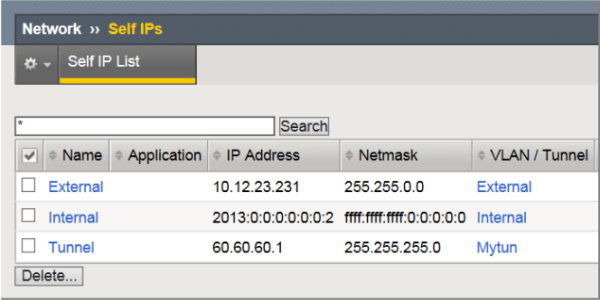
- The
Externalself IP address is an IPv4 address on the side of the BIG-IP system that faces the Internet. - The
Internalself IP address is an IPv6 address on the BIG-IP system, which is configured as a BR device. - The
Tunnelself IP address is the one you just created in this task.
Using the tmsh command-line interface, you can view statistics to help you diagnose issues with MAP tunnels.
-
Access the
tmshcommand-line utility. -
Type this command at the prompt.
tmsh show net tunnels map *profile*
This example shows the statistics displayed for the MAP tunnel using the profile map-profile.
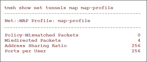
- Spoof Packets: The number of IPv4 packets that fail MAP self-consistency checks.
- Misdirected Packets: The number of IPv4 packets sent to the wrong MAP domain or wrong protocol number.
- Address Sharing Ratio: The number of users sharing one IP address.
- Ports per user: The number of ports each user behind the CE can use.
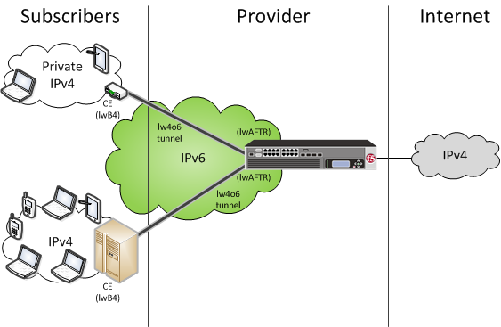
Lightweight 4over6 (lw4o6) functionality is an IPv4 to IPv6 transition technology that provides IPv4 service over an IPv6-only network. A lw4o6 configuration refines DS-Lite functionality to reduce the network address and port translation (NAPT44) states in a service provider’s network. In a lw4o6 configuration, lwB4 customer edge (CE) devices, provisioned with a public IP address and a port set, perform NAPT, as well as encapsulation and decapsulation. The implementation of lw4o6 on the BIG-IPsystem complies with RFC 7596.
Note: You must configure the CE functionality of the lw4o6 solution on the CE device, not on the BIG-IP system.
A lw4o6 configuration includes the following components:
- lwB4. Provides NAPT, as well as encapsulation and decapsulation of IPv4 and IPv6. Each lwB4 must be provisioned with a public IPv4 address and port set, restricting the external ports used by NAPT to source packets.
- lwAFTR. Encapsulates and decapsulates IPv4 and IPv6. It also forwards incoming packets to the applicable lwB4, and forwards outgoing packets to the IPv4 network.
- Provisioning. Configures the lwB4 with the public IPv4 address and port set.
This illustration shows the position of a BIG-IP system in a lw4o6 configuration. The BIG-IP system decapsulates the encapsulated IPv6 traffic and forwards it to the public IPv4 Internet. The reverse sequence is performed for response traffic.
In this example, a service provider transports encapsulated IPv4 traffic over its IPv6 network.
Following is an example of an lw4o6 binding table.
--------------------------
# text_csv
# psid_len 1
#
# IPv4                  IPv6 prefix         PSID
10.100.10.211,      2015:a000:0000:0000,     0,
10.100.10.211,      2015:a000:0000:0000,     1,
10.100.10.212,      2015:a000:0000:0001,     0,
10.100.10.212,      2015:a000:0000:0001,     1,
10.100.10.213,      2015:a000:0000:0002,     0,
10.100.10.213,      2015:a000:0000:0002,     1,
10.100.10.215,      2015:a000:0000:0003,     0,
10.100.10.215,      2015:a000:0000:0003,     1,
#end file Before you configure the BIG-IP® system for a lw4o6 domain, ensure that you have licensed CGNAT on the BIG-IP system. Optionally, the BIG-IP system can provide an IPv6 self IP address, an IPv6 default gateway, and an IPv4 self IP address on the side of the BIG-IP system that faces the Internet.
Make sure that the CE devices are configured for lw4o6. For instructions on configuring a CE device, consult the manufacturer’s documentation.
Using the BIG-IP Configuration utility, you can import an lw4o6 file from another system to use when creating an lw4o6 profile.
-
On the Main tab, click System > File Management > lw4o6 Tables > Import.
-
Browse for the file and click Open.
The name of the file you select appears in the File Name setting.
-
In the Name field, type a new name for the file, such as
lwtunneltbl. -
Click the Import button.
The new name appears in the list of imported files.
After importing an lw4o6 file onto the system, you must create an lw4o6 profile, specifying the lw4o6 file that you imported.
You must create a new lw4o6 profile to specify the parameters for a lw4o6 tunnel. You do this by customizing the system-supplied lw4o6 profile, lw4o6.
-
On the Main tab, click Network > Tunnels > Profiles > lw4o6 > Create, or click Carrier Grade NAT > Tunnel Profiles > lw4o6 > Create.
The New lw4o6 Profile screen opens.
-
In the Name field, type a unique name for the profile.
-
From the lw4o6 Table list, select a table.
-
In the PSID Length field, type a value for the port set identifier.
Note: Specifying this value for the port set identifier allows only TCP, UDP, or ICMP traffic to pass through the lw4o6 tunnel. You can, however, specify a value of
0and select the Pass All Protocols check box to allow all IP sub-protocols to pass through. -
To pass through all IP sub-protocols, select the Pass All Protocols check box, and ensure that the PSID Length value is
0.Note: If you specify a PSID Length value other than
0, the Pass All Protocols check box is cleared to allow only TCP, UDP, or ICMP traffic to pass through the lw4o6 tunnel. -
Click Finished.
The lw4o6 profile you created now appears in the Profiles list on the New Tunnel screens.
Before creating an lw4o6 tunnel on a BIG-IP system, you must have configured an lw4o6 tunnel profile.
You create an lw4o6 tunnel on a BIG-IP system to carry IPv4 traffic over an IPv6 network, allowing users to seamlessly access the IPv4 Internet.
-
On the Main tab, click Network > Tunnels > Tunnel List > Create or Carrier Grade NAT > Tunnels > Create.
The New Tunnel screen opens.
-
In the Name field, type a unique name for the tunnel.
-
From the Profile list, select lw4o6 or the lw4o6 profile you created previously.
-
In the Local Address field, type the IPv6 address of the local BIG-IP device.
-
For the Remote Address list, retain the default selection, Any.
-
Click Finished.
After you create an lw4o6 tunnel, you must create a virtual server to forward IPv4 traffic.
After you configure an lw4o6 tunnel to transport IPv4 traffic over an IPv6 network, you need to create a virtual server to intercept the IPv4 traffic and forward the packets to their destinations.
-
On the Main tab, click Carrier Grade NAT > Virtual Servers.
The Virtual Server List screen opens.
-
Click Create.
The New Virtual Server screen opens.
-
In the Name field, type a unique name for the virtual server.
-
From the Type list, select Forwarding (IP).
-
In the Destination Address/Mask field, type
0.0.0.0to accept any IPv4 traffic. -
Click Finished.
Before starting this task, ensure that you have created an lw4o6 tunnel.
Self IP addresses can enable the BIG-IP system, and other devices on the network, to route application traffic through the associated tunnel, similar to routing through VLANs and VLAN groups. If you specify a public IPv4 address in the same range as the CE devices, the system automatically creates a connected route on the BIG-IP platform, which can be used to route IPv4 traffic back to this lw4o6 domain. The alternative is to add a static route manually.
-
On the Main tab, click Network > Self IPs.
-
Click Create.
The New Self IP screen opens.
-
In the Name field, type a unique name for the self IP address.
-
In the IP Address field, type the IPv4 address of the tunnel, which is an IP address that belongs to the network of the CE devices.
Note: This is not the same as the IP address of the tunnel local endpoint.
-
In the Netmask field, type the network mask for the specified IP address.
-
From the VLAN/Tunnel list, select the tunnel with which to associate this self IP address.
-
Click Finished.
The screen refreshes, and displays the new self IP address.
Assigning a self IP address to a tunnel ensures that the tunnel appears as a resource for routing traffic.
- The
Externalself IP address is an IPv4 address on the side of the BIG-IP system that faces the Internet. - The
Internalself IP address is an IPv6 address on the BIG-IP system. - The
Tunnelself IP address is the one you just created in this task.
Using the tmsh command-line interface, you can view statistics to help you diagnose issues with lw4o6 tunnels.
-
Access the
tmshcommand-line utility. -
Type this command at the prompt.
tmsh show net tunnels lw4o6 *lw4o6\_profile*
The screen displays lw4o6 tunnel statistics for the specified lw4o6 profile.