Updated Date: 07/07/2026
Using ALG Profiles
The File Transfer Protocol (FTP) application layer gateway (ALG) profile enables you to transfer files between a client and server. The FTP ALG profile supports both active and passive modes, where data connections are initiated either from an FTP server (active mode) or from a client (passive mode). You can transfer files using the FTP protocol by configuring an LSN pool, configuring an FTP profile, and then assigning the LSN pool and FTP profile to a virtual server. The FTP protocol is described in RFC 959.
The File Transfer Protocol (FTP) profile enables you to transfer files between a client and server, using FTP connections over TCP. The FTP application layer gateway (ALG) supports the FTP protocol’s active and passive modes, where data connections are initiated either from an FTP server (active mode) or from a client (passive mode).
You can configure the FTP profile settings, as needed, to ensure compatibility between IPv4 and IPv6 clients and servers, to enable the FTP data channel to inherit the TCP profile used by the FTP control channel, and to use a port other than the default port (20). Additionally, when used with Application Security Manager™ (ASM™), this profile enables the BIG-IP system to inspect FTP traffic for security vulnerabilities by using an FTP security profile.
Once established, the FTP control channel remains open throughout the FTP session. The FTP control channel and the FTP data channel must both originate from the same IP address.
In active mode, the FTP server initiates data connections. A client informs the server as to what port the client is listening on, and the server connects to the client by using that port.
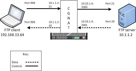
In this example, an LSN pool is configured with a translation IP address and prefix length of 10.33.1.0/24. The virtual server is configured with an FTP control port using a wildcard address and a specific port: 0.0.0.0:21. The FTP data port is configured to use port 20. The configured translation mode uses the values of the respective port range.
| Translation mode | Port range |
|---|---|
| NAPT | 2000-3000 |
| DNAT | 2000-2200 |
| PBA | 2000-2150 |
In passive mode, the FTP client initiates data connections. The FTP server informs the client as to what port the server is listening on, and the client connects to the server by using that port.
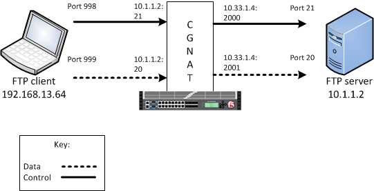
In this example, an LSN pool is configured with a translation IP address and prefix length of 10.33.1.0/24. The virtual server is configured with an FTP control port using a wildcard address and a specific port: 0.0.0.0:21. The FTP data port is configured to use port 20. In this example, the configured translation mode uses the values of the respective port range.
| Translation mode | Port range |
|---|---|
| NAPT | 2000-3000 |
| DNAT | 2000-2200 |
| PBA | 2000-2150 |
The carrier-grade NAT (CGNAT) module must be enabled with the appropriate settings before you can create large-scale NAT (LSN) pools.
LSN pools are used by the CGNAT module to allow efficient configuration of translation prefixes and parameters.
-
On the Main tab, click Carrier Grade NAT > LSN Pools.
The LSN Pool List screen opens.
-
Click Create.
-
In the Name field, type a unique name.
-
In the Configuration area, for the Persistence Mode setting, select Address or Address Port.
-
For the Member List setting, type an address and a prefix length in the Address/Prefix Length field, and click Add.
If your pool uses deterministic mode, ensure that any address ranges you enter as a member do not overlap another member’s prefix address ranges. For example, the address and prefix
10.10.10.0/24overlaps10.10.10.0/23. -
Click Finished.
You can configure a file transfer protocol (FTP) profile on the BIG-IP system that transfers files, either in an active or passive mode, and logs related messages.
-
On the Main tab, click Carrier Grade NAT > ALG Profiles > FTP.
The FTP screen opens and displays a list of available FTP ALG profiles.
-
Click Create.
-
Type a name for the profile.
-
From the Parent Profile list, select a parent profile.
-
Select the Custom check box.
-
Select the Translate Extended check box to ensure compatibility between IPv4 and IPv6 clients and servers when using the FTP protocol.
The default is selected.
-
Select the Inherit Parent Profile check box to enable the FTP data channel to inherit the TCP profile used by the control channel. The check box is clear by default.
Note: If this setting is disabled, the data channel uses FastL4 (BigProto) only.
-
In the Data Port field, type a number for an alternate port.
The default value for the FTP data port is
20. -
Click Finished.
An FTP profile is configured on the BIG-IP system that transfers files, either in an active or passive mode, and logs related messages.
You create iRules to automate traffic forwarding for XML content-based routing. When a match occurs, an iRule event is triggered, and the iRule directs the individual request to an LSN pool, a node, or virtual server.
-
On the Main tab, click Carrier Grade NAT > iRules.
The iRule List screen opens.
-
Click Create.
-
In the Name field, type a 1 to 31 character name, such as
cgn_https_redirect_iRule. -
In the Definition field, type the syntax for the iRule using Tool Command Language (Tcl) syntax.
For complete and detailed information about iRules syntax, see the F5 Networks DevCentral web site (
http://devcentral.f5.com). -
Click Finished.
You now have an iRule to use with a CGNAT virtual server.
Virtual servers are matched based on source (client) addresses. Define a virtual server in order to reference an FTP profile and LSN pool.
-
On the Main tab, click Carrier Grade NAT > Virtual Servers.
The Virtual Server List screen opens.
-
Click Create.
The New Virtual Server screen opens.
-
In the Name field, type a unique name for the virtual server.
-
From the Type list, retain the default setting Standard.
-
For the Destination Address/Mask setting, confirm that the Host button is selected, and type the IP address in CIDR format.
The supported format is address/prefix, where the prefix length is in bits. For example, an IPv4 address/prefix is
10.0.0.1or10.0.0.0/24, and an IPv6 address/prefix isffe1::0020/64or2001:ed8:77b5:2:10:10:100:42/64. When you use an IPv4 address without specifying a prefix, the BIG-IP system automatically uses a/32prefix.Note: The IP address you type must be available and not in the loopback network.
-
In the Service Port field, type
21or select FTP from the list. -
From the Protocol list, select TCP.
-
From the Protocol Profile (Client) list, select a predefined or user-defined TCP profile.
-
From the Protocol Profile (Server) list, select a predefined or user-defined TCP profile.
-
From the FTP Profile list, select an FTP ALG profile for the virtual server to use.
-
For the LSN Pool setting, select the pool that this server will draw on for addresses.
-
Locate the Resources area of the screen; for the Related iRules setting, from the Available list, select the name of the iRule that you want to assign and move the name to the Enabled list.
This setting applies to virtual servers that reference a profile for a data channel protocol, such as FTP or RTSP.
-
Click Finished.
The custom CGNAT virtual server appears in the CGNAT Virtual Servers list.
You can create an application layer gateway (ALG) logging profile, and associate it with one or more FTP ALG profiles, to allow you to configure logging options for various events that apply to high-speed logging (HSL) destinations. A logging profile decreases the need to maintain a number of customized profiles where the events are very similar.
-
On the Main tab, click Carrier Grade NAT > Logging Profiles > ALG.
The ALG logging profiles screen opens.
-
On the Main tab, click Local Traffic > Profiles > Other > ALG Logging.
The ALG Logging screen opens.
-
Click Create.
The New ALG Logging Profile screen opens.
-
In the Name field, type a unique name for the logging profile.
-
From the Parent Profile list, select a profile from which the new profile inherits properties.
-
For the Log Settings area, select the Custom check box.
-
For the Log Settings area, select Enabled for the following settings, as necessary.
Setting Description CSV Format Generates log entries in comma-separated-values (csv) format. Start Control Channel Generates event log entries at the start of a control channel connection for an ALG client. End Control Channel Generates event log entries at the end of a control channel connection for an ALG client. Start Data Channel Generates event log entries at the start of a data channel connection for an ALG client. End Data Channel Generates event log entries at the end of a data channel connection for an ALG client. Inbound Transaction Generates event log entries of ALG messages triggered by an inbound connection to the BIG-IP system. Note: Enabling the CSV check box affects splunk logs because IP addresses are shown as
ip,port,rtdominstead ofip%rtdom:port. Do not mix log types and only use standard syslog formats. -
Click Finished.
You can associate an FTP ALG profile with a log publisher and logging profile that the BIG-IP system uses to send log messages to a specified destination.
-
On the Main tab, click Carrier Grade NAT > ALG Profiles > FTP.
The FTP screen opens and displays a list of available FTP ALG profiles.
-
Click the name of an FTP profile.
-
In the Log Settings area, from the Log Publisher list, select the log publisher the BIG-IP system uses to send log messages to a specified destination.
Note: If you configure a log publisher, you must also configure a Logging Profile.
Important: If you configure a log publisher to use multiple logging destinations, then, by default, all logging destinations must be available in order to log to each destination. Unless all logging destinations are available, no logging can occur. If you want to log to the available logging destinations when one or more destinations become unavailable, you must set the
logpublisher.atomicdb variable to false. -
From the Logging Profile list, select the logging profile the BIG-IP system uses to configure logging options for various ALG events.
Note: If you configure a Logging Profile, you must also configure a Log Publisher.
-
Click Finished.
The Trivial File Transfer Protocol (TFTP) profile enables you to configure the BIG-IP system to read and write files from or to a remote server. The TFTP application layer gateway (ALG) profile is associated with a UDP port 69 virtual server so that a listener is established for incoming TFTP traffic. This allows the protocol to operate across the BIG-IP system. You can transfer files using the TFTP protocol by configuring a TFTP profile, configuring an LSN pool, and then assigning the TFTP profile and LSN pool to a virtual server. The TFTP protocol is described in RFC 1350.
The Trivial File Transfer Protocol application layer gateway (TFTP ALG) provides connection management for TFTP. The TFTP profile is configured on a UDP port 69 virtual server. The profile opens a server-side listener so that responses from the server can be returned to the client across the BIG-IP system. ALG logging can be configured on the profile.
You can configure a Trivial File Transfer Protocol (TFTP) on the BIG-IP system to read and write files from or to a remote server.
-
On the Main tab, click Carrier Grade NAT > ALG Profiles > TFTP.
The TFTP screen opens and displays a list of available TFTP ALG profiles.
-
On the Main tab, click Carrier Grade NAT > ALG Profiles > TFTP.
The TFTP screen opens and displays a list of available TFTP ALG profiles.
-
Click Create.
The New TFTP Profile screen opens.
-
In the Name field, type a unique name for the TFTP profile.
-
From the Parent Profile list, select a profile from which the new profile inherits properties.
-
For the Settings area, select the Custom check box.
-
In the Settings area, for the Idle Timeout list, type a number to specify the number of seconds after a connection is eligible for deletion; when the connection has no traffic. The default value is 30 seconds.
-
For the Log Settings area, select the Custom check box.
-
In the Log Settings area, from the Log Publisher list, select the log publisher the BIG-IP system uses to send log messages to a specified destination.
Note: If you configure a log publisher, you must also configure a Logging Profile.
Important: If you configure a log publisher to use multiple logging destinations, then, by default, all logging destinations must be available in order to log to each destination. Unless all logging destinations are available, no logging can occur. If you want to log to the available logging destinations when one or more destinations become unavailable, you must set the
logpublisher.atomicdb variable to false. -
From the Logging Profile list, select the logging profile the BIG-IP system uses to configure logging options for various ALG events.
Note: If you configure a Logging Profile, you must also configure a Log Publisher.
-
Click Finished.
The carrier-grade NAT (CGNAT) module must be enabled with the appropriate settings before you can create large-scale NAT (LSN) pools.
LSN pools are used by the CGNAT module to allow efficient configuration of translation prefixes and parameters.
-
On the Main tab, click Carrier Grade NAT > LSN Pools.
The LSN Pool List screen opens.
-
Click Create.
-
In the Name field, type a unique name.
-
In the Configuration area, for the Persistence Mode setting, select Address or Address Port.
-
For the Member List setting, type an address and a prefix length in the Address/Prefix Length field, and click Add.
If your pool uses deterministic mode, ensure that any address ranges you enter as a member do not overlap another member’s prefix address ranges. For example, the address and prefix
10.10.10.0/24overlaps10.10.10.0/23. -
Click Finished.
Virtual servers are matched based on source (client) addresses. Create and define a virtual server that references an TFTP profile and LSN pool.
-
On the Main tab, click Carrier Grade NAT > Virtual Servers.
The Virtual Server List screen opens.
-
Click Create.
The New Virtual Server screen opens.
-
In the Name field, type a unique name for the virtual server.
-
From the Type list, retain the default setting Standard.
-
In the Destination Address/Mask field, type the IP address in CIDR format.
The supported format is address/prefix, where the prefix length is in bits. For example, an IPv4 address/prefix is
10.0.0.1or10.0.0.0/24, and an IPv6 address/prefix isffe1::0020/64or2001:ed8:77b5:2:10:10:100:42/64. When you use an IPv4 address without specifying a prefix, the BIG-IP system automatically uses a/32prefix. -
In the Service Port field, type
69or select TFTP from the list. -
From the Configuration list, select Advanced.
-
From the Protocol list, select UDP.
-
From the TFTP Profile list, select an TFTP ALG profile for the virtual server to use.
-
For the LSN Pool setting, select the pool that this server will draw on for addresses.
-
Click Finished.
You can create an application layer gateway (ALG) logging profile, and associate it with one or more Trivial File Transfer Protocol (TFTP) ALG profiles, to allow you to configure logging options for various events. A logging profile decreases the need to maintain a number of customized profiles where the events are very similar.
-
On the Main tab, click Carrier Grade NAT > Logging Profiles > ALG.
The ALG logging profiles screen opens.
-
Click Create.
The New ALG Logging Profile screen opens.
-
In the Name field, type a unique name for the TFTP profile.
-
From the Parent Profile list, select a profile from which the new profile inherits properties.
-
For the Log Settings area, select the Custom check box.
-
For the Log Settings area, select Enabled for the following settings, as necessary.
Setting Description CSV Format Generates log entries in comma-separated-values (csv) format. Start Control Channel Generates event log entries at the start of a control channel connection for an ALG client. End Control Channel Generates event log entries at the end of a control channel connection for an ALG client. Start Data Channel Generates event log entries at the start of a data channel connection for an ALG client. End Data Channel Generates event log entries at the end of a data channel connection for an ALG client. Inbound Transaction Generates event log entries of ALG messages triggered by an inbound connection to the BIG-IP system. Note: Enabling the CSV check box affects splunk logs because IP addresses are shown as
ip,port,rtdominstead ofip%rtdom:port. Do not mix log types and only use standard syslog formats. -
Click Finished.
A carrier-grade network address translation (CGNAT) Session Initiation Protocol (SIP) application layer gateway (ALG) configuration, using message routing framework (MRF) functionality, enables SIP communication and associated media flow to cross an address translation boundary.
The SIP ALG profile provides the ability for subscribers to make and accept calls, and to store private contact information with a corresponding translated address and port. The lifetime and idle timeout for this entry differs from the flow that created it, enabling the entry to live after the flow expires. The SIP ALG uses the translated IP address and port to uniquely identify a subscriber, and to accept that subscriber’s incoming calls. To enable this functionality, the LSN pool must pick an endpoint that is not reserved for the SIP ALG connections, and update the endpoint reservation time.
For calls between subscribers, a BIG-IP device can hairpin media; however, it must not hairpin SIP signaling. Instead, the BIG-IP device must always deliver SIP signaling to an external proxy.
Additionally, for communication between subscribers, a BIG-IP device supports NAT44, NAT64, 464XLAT, and DS-Lite translation.
Finally, the SIP ALG profile supports media flow between a caller and callee.
SIP MRF ALG call scenarios include the following:
- Internal to internal calls, with SIP signaling through the proxy
- External to internal calls
- Internal to external calls
- Internal to external calls through NAT64
- Calls through DS-Lite tunnels on the internal network, including the following:
- DS-Lite subscribers on different tunnels with the same name and IP address
- DS-Lite subscribers on different tunnels with the same name and different IP addresses
- DS-Lite subscribers on different tunnels with different names and the same IP address
A SIP MRF virtual server must include both a SIP session profile and a SIP router profile. The SIP session profile provides a protocol-specific configuration, and the SIP router profile specifies the static-route configurations.
Important: The SIP Session profile and SIP Router profile are only available for use with a Message Routing virtual server.
A SIP session profile, assigned to a message routing virtual server, processes ingress and egress messages in accordance with the profile configuration. Multiple SIP session profiles can be assigned to a virtual server, as necessary, to manage SIP messages. Each SIP session ALG profile includes settings for the message size, message header count, and message header size.
A SIP router profile, assigned to one or more message routing virtual servers, specifies an operation mode, static routes, traffic group, and connection mirroring, as well as session, media proxy, registration, and logging parameters.
For virtual servers that use a SIP router profile in an application layer gateway (ALG) operation mode, the SIP router profile binds the virtual servers together; however, routes are not configured. Instead, the local address of the originating flow is used as the remote address of the outgoing connection.
Create a SIP session profile to define how the BIG-IP system processes SIP messages, including the data the system uses to persist SIP connections.
-
On the Main tab, click Local Traffic > Profiles > Message Routing > SIP.
The SIP transport config list screen opens.
-
On the menu bar, click Session Profiles.
The Session Profiles list screen opens.
-
Click Create.
The New SIP Session Profile screen opens.
-
In the Name field, type a unique name for the SIP session profile.
-
From the Persist Key list, select the value the system uses for persistence of a SIP session. The options are:
Option Description Call-ID The system uses the value in the Call-ID header field in the SIP message. Custom The system uses the value of a custom key specified in an iRule. Src-Addr The system uses the originating IP address in the SIP message. -
From the Persist Type list, select one of these options:
Option Description Session Persistence is enabled. None Persistence is disabled. -
In the Persist Timeout (seconds) field, type the number of seconds before a SIP session persistence record expires.
-
Click Finished.
You can create a SIP router profile with mirroring functionality for a SIP ALG firewall configuration.
Note: If you do not want to configure mirroring functionality, you can configure a virtual server to use the default settings provided in the preconfigured siprouter-alg profile.
-
On the Main tab, click Local Traffic > Profiles > Message Routing > SIP.
The SIP session profiles list screen opens.
-
On the menu bar, click Router Profiles.
The Router Profiles list screen opens.
-
Click Create.
The New Router Profiles screen opens.
-
In the Name field, type a unique name for the router profile.
-
In the Settings area, select the Custom check box.
-
From the Operation Mode list, select Application Level Gateway.
-
To use connection mirroring, configure the Traffic Group setting.
-
Clear the Inherit traffic group from current partition / path check box.
-
From the list, select a traffic group, such as, traffic-group-1.
Important: Changing traffic groups, with Connection Mirroring enabled, drops all mirrored connections and loses all persistence data. If you change traffic groups, mirroring must restart.
Note: The traffic group for the virtual address and mirrored attribute are overwritten by the attached router profile.
-
-
Select the Connection Mirroring check box.
Note: For connection mirroring to properly function, this device must be a member of a device group.
-
In the Mirrored Message Sweeper Interval field, type the milliseconds for the frequency of the mirrored message sweeper.
-
Click Finished.
A SIP router profile appears in the Router Profiles list.
The carrier-grade NAT (CGNAT) module must be enabled with the appropriate settings before you can create large-scale NAT (LSN) pools.
LSN pools are used by the CGNAT module to allow efficient configuration of translation prefixes and parameters. You can configure the following types of LSN pools:
- NAPT
- Deterministic
- PBA
A carrier-grade NAT (CGNAT) Session Initiation Protocol (SIP) application layer gateway (ALG) configuration supports certain large-scale NAT (LSN) modes and network configurations.
|
NAT Mode |
Supported Network Configurations |
|---|---|
|
NAPT |
|
|
DNAT |
|
|
PBA |
|
- The CGNAT module must be provisioned before LSN pools can be configured.
- Before associating a LSN pool with a log publisher, ensure that at least one log publisher exists on the BIG-IP system.
Large Scale NAT (LSN) pools are used by the CGNAT module to allow efficient configuration of translation prefixes and parameters.
-
On the Main tab, click Carrier Grade NAT > LSN Pools.
The LSN Pool List screen opens.
-
Click Create.
-
In the Name field, type a unique name.
-
In the Description field, type a description.
-
Select NAPT for the pool’s translation Mode.
-
Click Finished.
Your NAPT LSN pool is now ready and you can continue to configure your CGNAT.
The CGNAT module must be provisioned before you can configure LSN pools.
Large Scale NAT (LSN) pools are used by the CGNAT module to allow efficient configuration of translation prefixes and parameters.
-
On the Main tab, click Carrier Grade NAT > LSN Pools.
The LSN Pool List screen opens.
-
Click Create.
-
In the Name field, type a unique name.
-
For the Mode setting, select Deterministic for the pool’s translation.
Note that deterministic mode does not support DS-lite tunneling or NAT64.
-
From the Log Publisher list, select the publisher that includes the destinations to which you want to send log messages.
-
In the Configuration area, for the Member List setting, type an address and a prefix length in the Address/Prefix Length field, and click Add.
If your pool uses deterministic mode, ensure that any address ranges you enter as a member do not overlap another member’s prefix address ranges. For example, the address and prefix
10.10.10.0/24overlaps10.10.10.0/23. -
For deterministic mode, the Backup Member List must have at least one member, so type an address in the Address/Prefix Length field and click Add.
-
Click Finished.
Your deterministic LSN pool is now ready, and you can continue to configure your CGNAT.
- The CGNAT module must be provisioned before LSN pools can be configured.
- Before associating a LSN pool with a log publisher, ensure that at least one log publisher exists on the BIG-IP system.
You configure Large Scale NAT (LSN) pools for the CGNAT module to use in allowing efficient configuration of translation prefixes and parameters.
-
On the Main tab, click Carrier Grade NAT > LSN Pools.
The LSN Pool List screen opens.
-
Click Create.
-
In the Name field, type a unique name.
-
In the Description field, type a description.
-
For the Mode setting, select PBA for the pool’s translation.
Note that PBA mode for DS-lite is same as for NAT44, except that all clients behind the DS-Lite tunnel are managed as one subscriber. Port block limits are in accordance with each DS-lite tunnel.
-
For the Port Block Allocation setting, specify your preferred PBA configuration.
-
In the Block Size field, type the number of ports designated for a block.
-
In the Block Lifetime field, type the number of seconds before a port block times out.
Note: If you type a timeout other than
0, you can also specify a Zombie Timeout. A Block Lifetime value that is less than the Persistence Timeout value minimizes the number of zombie port blocks. The default value of0specifies no lifetime limit and indefinite use of the port block. -
In the Block Idle Timeout field, enter the timeout (in seconds) for after the port block becomes idle.
Note: Typically, you want to use a Block Idle Timeout value less than the Persistence Timeout value, to minimize the number of zombie port blocks.
-
In the Client Block Limit field, type the number of blocks that can be assigned to a single subscriber IP address.
-
In the Zombie Timeout field, type the number of seconds before port block times out.
A zombie port block is a timed out port block with one or more active connections. The default value of
0specifies no timeout and an indefinite zombie state for the port block, as long as connections remain active. A value other than0specifies a timeout expiration, upon which existing connections are terminated, and the port block is released and returned to the pool.
-
-
In the Configuration area, for the Member List setting, type an address and a prefix length in the Address/Prefix Length field, and click Add.
-
Click Finished.
Your PBA LSN pool is now ready, and you can continue to configure your CGNAT.
Before you can create a SIP virtual server, you need to create a SIP ALG session profile and a SIP ALG router profile.
You can create a SIP virtual server to provide source address translation and manage messages as configured in the SIP session profile and SIP router profile.
-
On the Main tab, click Carrier Grade NAT > Virtual Servers.
The Virtual Server List screen opens.
-
Click Create.
The New Virtual Server screen opens.
-
In the Name field, type a unique name for the virtual server.
-
In the Description field, type a description for the virtual server.
-
From the Type list, select Message Routing.
-
In the Destination Address/Mask field, type an IP address in CIDR format.
The supported format is address/prefix, where the prefix length is in bits. For example, to select all IP addresses, an IPv4 address/prefix is
0.0.0.0/0, and an IPv6 address/prefix is::/0. To specify a network, an IPv4 address/prefix is10.07.0.0or10.07.0.0/24, and an IPv6 address/prefix isffe1::/64or2001:ed8:77b5::/64. When you use an IPv4 address without specifying a prefix, the BIG-IP system automatically uses a/32prefix.Note: For best results, F5 recommends that you enter the subnet that matches your destination server network.
-
In the Service Port field, type
5060. -
From the Configuration list, select Advanced.
-
From the Application Protocol list, select SIP.
-
From the Session Profile list, select a SIP session ALG profile.
-
From the Router Profile list, select a SIP router ALG profile.
-
From the Source Address Translation list, select LSN.
-
From the LSN Pool list, select an LSN pool.
-
Click Finished.
A SIP virtual server is configured to provide source address translation and manage messages as configured in the SIP session profile and SIP router profile.
When an LSN pool or AFM Dynamic PAT source translation is configured, you can view information for the reserved endpoints using the TMSH (TMOS Shell) command-line interface.
Important: You can run the tmsh command run util lsndb from route domain 0 only. Running the command from a non-zero route domain produces an error message similar to the following:
Error: Connection to internal DB failed (err: Connection refused [111]).-
Access the
tmshcommand-line utility. -
At the command prompt, type
tmsh run util lsndb list endpoint_reservationsortmsh run util lsndb list all.A listing similar to the following example appears.
# tmsh run util lsndb list endpoint-reservations
LSN Endpoint Reservations
Translation                 Subscriber ID    Client          DS-Lite tunnel   Proto   Age
-------------------------------------------------------------------------------------------
5.5.5.1:1035                No-lookup       10.0.0.0:1035                    UDP     9
5.5.5.1:1025                No-lookup       10.0.0.0:1025                    TCP     14
5.5.5.1:1025                No-lookup       10.0.0.0:1025                    UDP     14
5.5.5.1:1033                No-lookup       10.0.0.0:1033                    UDP     9
5.5.5.2:5033                No-lookup       10.0.0.1:6000                    UDP     9
5 endpoint reservations found
# tmsh run util lsndb list all
LSN Client Connections
Client                                      Connections
-------------------------------------------------------------------------------------------
0 client with 0 connection found.
LSN Persistence Entries
Client                                      Translation     TTL
-------------------------------------------------------------------------------------------
0 persist entries found.
LSN port block allocations
Client                                      Port block      TTL
-------------------------------------------------------------------------------------------
0 port block entries found.
LSN Inbound Mapping Entries
Translation                 Subscriber ID   Client          DS-Lite tunnel   Proto   Age
-------------------------------------------------------------------------------------------
0 inbound mappings found.
LSN Endpoint Reservations
Translation                 Subscriber ID   Client          DS-Lite tunnel   Proto   Age
-------------------------------------------------------------------------------------------
5.5.5.1:1035                No-lookup       10.0.0.0:1035                    UDP     9
5.5.5.1:1025                No-lookup       10.0.0.0:1025                    TCP     14
5.5.5.1:1025                No-lookup       10.0.0.0:1025                    UDP     14
5.5.5.1:1033                No-lookup       10.0.0.0:1033                    UDP     9
5.5.5.2:5033                No-lookup       10.0.0.1:6000                    UDP     9
5 endpoint reservations found
PCP Entries
Client                                      Translation     Proto     Lifetime   Age
-------------------------------------------------------------------------------------------
0 PCP entries found.

# lsndb summary endpoint-reservations
--------------------------------------------------------------------------------------------
Summary:
LSN Endpoint Reservation Entries
Translation Address                         Client Count
-------------------------------------------------------------------------------------------
5.5.5.1                                     4
5.5.5.2                                     1
Total:                                      5
The Real Time Streaming Protocol (RTSP) application layer gateway (ALG) profile enables you to establish streaming multimedia sessions between a client and a server. You can stream multimedia sessions by configuring an LSN pool, configuring an RTSP profile, and then assigning the LSN pool and RTSP profile to a virtual server. The RTSP protocol is described in RFC 2326.
The Real Time Streaming Protocol (RTSP) profile enables you to stream multimedia content between a client and server, using RTSP connections over TCP. The RTSP application layer group (ALG) supports the RTSP protocol’s control channel to an RTSP server, through which the client requests a file for the server to stream (and controls the streaming of that file with commands like play or pause). The client can request streaming over UDP and provide two listening ports for the server response. The RTSP server responds with a Real-Time Transport Protocol (RTP) data channel port, to stream the requested file, and a Real-Time Control Protocol (RTCP) control channel port, which provides a stream description and status.
Note: You can specify RTP and RTCP port numbers in the RTSP profile, which only apply when a client connects to a Windows Media server. If you configure RTP and RTCP port numbers, both values must be nonzero.
You can configure the RTSP profile settings, as needed.
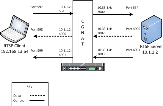
In this example, an LSN pool is configured with a translation IP address and prefix length of 10.33.1.0/24. The virtual server is configured with an RTSP control port using a wildcard address and a specific port: 0.0.0.0:554. The configured translation mode uses the values of the respective port range.
| Translation mode | Port range |
|---|---|
| NAPT | 2000-3000 |
| DNAT | 2000-2200 |
| PBA | 2000-2150 |
The carrier-grade NAT (CGNAT) module must be enabled with the appropriate settings before you can create large-scale NAT (LSN) pools.
LSN pools are used by the CGNAT module to allow efficient configuration of translation prefixes and parameters.
-
On the Main tab, click Carrier Grade NAT > LSN Pools.
The LSN Pool List screen opens.
-
Click Create.
-
In the Name field, type a unique name.
-
In the Configuration area, for the Persistence Mode setting, select Address or Address Port.
-
For the Member List setting, type an address and a prefix length in the Address/Prefix Length field, and click Add.
If your pool uses deterministic mode, ensure that any address ranges you enter as a member do not overlap another member’s prefix address ranges. For example, the address and prefix
10.10.10.0/24overlaps10.10.10.0/23. -
Click Finished.
You can configure a real time streaming protocol (RTSP) profile on the BIG-IP system that streams multimedia content between a client and server.
-
On the Main tab, click Carrier Grade NAT > ALG Profiles > RTSP.
The RTSP screen opens and displays a list of available RTSP ALG profiles.
-
Click Create.
-
Type a name for the profile.
-
From the Parent Profile list, select a parent profile.
-
Select the Custom check box.
-
In the RTP Port field, type the port number that a Microsoft Media Services server uses. The default is
0.Note: You can specify Real-Time Transport Protocol (RTP) and Real-Time Control Protocol (RTCP) port numbers in the RTSP profile, which only apply when a client connects to a Windows Media server. If you configure RTP and RTCP port numbers, both values must be nonzero.
-
In the RTCP Port field, type the port number that a Microsoft Media Services server uses. The default is
0.Note: You can specify Real-Time Transport Protocol (RTP) and Real-Time Control Protocol (RTCP) port numbers in the RTSP profile, which only apply when a client connects to a Windows Media server. If you configure RTP and RTCP port numbers, both values must be nonzero.
-
Click Finished.
An RTSP profile is configured on the BIG-IP system that streams multimedia content between a client and server.
You create iRules to automate traffic forwarding for XML content-based routing. When a match occurs, an iRule event is triggered, and the iRule directs the individual request to an LSN pool, a node, or virtual server.
-
On the Main tab, click Carrier Grade NAT > iRules.
The iRule List screen opens.
-
Click Create.
-
In the Name field, type a 1 to 31 character name, such as
cgn_https_redirect_iRule. -
In the Definition field, type the syntax for the iRule using Tool Command Language (Tcl) syntax.
For complete and detailed information about iRules syntax, see the F5 Networks DevCentral web site (
http://devcentral.f5.com). -
Click Finished.
You now have an iRule to use with a CGNAT virtual server.
Virtual servers are matched based on source (client) addresses. Here are the steps to define a virtual server that references an RTSP profile and LSN pool.
-
On the Main tab, click Carrier Grade NAT > Virtual Servers.
The Virtual Server List screen opens.
-
Click Create.
The New Virtual Server screen opens.
-
In the Name field, type a unique name for the virtual server.
-
From the Type list, retain the default setting Standard.
-
For the Destination Address/Mask setting, confirm that the Host button is selected, and type the IP address in CIDR format.
The supported format is address/prefix, where the prefix length is in bits. For example, an IPv4 address/prefix is
10.0.0.1or10.0.0.0/24, and an IPv6 address/prefix isffe1::0020/64or2001:ed8:77b5:2:10:10:100:42/64. When you use an IPv4 address without specifying a prefix, the BIG-IP system automatically uses a/32prefix.Note: The IP address you type must be available and not in the loopback network.
-
In the Service Port field, type
554for the service. -
From the Protocol list, select TCP.
-
From the Protocol Profile (Client) list, select a predefined or user-defined TCP profile.
-
From the Protocol Profile (Server) list, select a predefined or user-defined TCP profile.
-
From the RTSP Profile list, select an RISP ALG profile for the virtual server to use.
-
For the LSN Pool setting, select the pool that this server will draw on for addresses.
-
Locate the Resources area of the screen; for the Related iRules setting, from the Available list, select the name of the iRule that you want to assign and move the name to the Enabled list.
This setting applies to virtual servers that reference a profile for a data channel protocol, such as FTP or RTSP.
-
Click Finished.
The custom CGNAT virtual server appears in the CGNAT Virtual Servers list.
You can create an ALG logging profile, and associate it with one or more RTSP ALG profiles, to allow you to configure logging options for various events that apply to high-speed logging (HSL) destinations. A logging profile decreases the need to maintain a number of customized profiles where the events are very similar.
-
On the Main tab, click Carrier Grade NAT > Logging Profiles > ALG.
The ALG logging profiles screen opens.
-
Click Create.
The New ALG Logging Profile screen opens.
-
In the Name field, type a unique name for the logging profile.
-
From the Parent Profile list, select a profile from which the new profile inherits properties.
-
For the Log Settings area, select the Custom check box.
-
For the Log Settings area, select Enabled for the following settings, as necessary.
Setting Description CSV Format Generates log entries in comma-separated-values (csv) format. Start Control Channel Generates event log entries at the start of a control channel connection for an ALG client. End Control Channel Generates event log entries at the end of a control channel connection for an ALG client. Start Data Channel Generates event log entries at the start of a data channel connection for an ALG client. End Data Channel Generates event log entries at the end of a data channel connection for an ALG client. Inbound Transaction Generates event log entries of ALG messages triggered by an inbound connection to the BIG-IP system. Note: Enabling the CSV check box affects splunk logs because IP addresses are shown as
ip,port,rtdominstead ofip%rtdom:port. Do not mix log types and only use standard syslog formats. -
Click Finished.
You can associate an RTSP ALG profile with a log publisher and logging profile that the BIG-IP system uses to send log messages to a specified destination.
-
On the Main tab, click Carrier Grade NAT > ALG Profiles > RTSP.
The RTSP screen opens and displays a list of available RTSP ALG profiles.
-
Click the name of an RTSP profile.
-
In the Log Settings area, from the Log Publisher list, select the log publisher the BIG-IP system uses to send log messages to a specified destination.
Note: If you configure a log publisher, you must also configure a Logging Profile.
Important: If you configure a log publisher to use multiple logging destinations, then, by default, all logging destinations must be available in order to log to each destination. Unless all logging destinations are available, no logging can occur. If you want to log to the available logging destinations when one or more destinations become unavailable, you must set the
logpublisher.atomicdb variable to false. -
From the Logging Profile list, select the logging profile the BIG-IP system uses to configure logging options for various ALG events.
Note: If you configure a Logging Profile, you must also configure a Log Publisher.
-
Click Finished.
The point-to-point tunneling protocol (PPTP) profile enables you to configure the BIG-IP system to support a secure virtual private network (VPN) tunnel that forwards PPTP control and data connections. You can create a secure VPN tunnel by configuring a PPTP Profile, and then assigning the PPTP profile to a virtual server. The PPTP protocol is described in RFC 2637.
Important: You cannot combine or use the PPTP Profile with another profile other than a TCP Profile. The PPTP Profile must be used separately and independently.
With the point-to-point tunneling protocol (PPTP) profile, you can configure the BIG-IP system to support a secure virtual private network (VPN) tunnel. A PPTP application layer gateway (ALG) forwards PPTP client control and data connections through the BIG-IP system to PPTP servers, and provides source address translation that allows multiple clients to share a single translation address.
Note: A PPTP client is also known as PPTP Access Concentrator (PAC). PPTP servers are also known as PPTP Network Servers (PNSs).
The PPTP profile defines a Transmission Control Protocol (TCP) control connection and a data channel through a PPTP Generic Routing Encapsulation (GRE) tunnel., This manages the PPTP tunnels through CGNAT for NAT44 and DS-Lite. It also manages all translation modes, including Network Address Port Translation (NAPT), Deterministic, and Port Block Allocation (PBA) modes.
The BIG-IP system proxies PPTP control channels as normal TCP connections. The PPTP profile translates outbound control messages, which contain Call Identification numbers (Call IDs) that match the port that is selected on the outbound side. Subsequently, for inbound control messages containing translated Call IDs, the BIG-IP system restores the original client Call ID. You can use a packet tracer to observe this translation on the subscriber side or on the Internet side. You can also use iRules® to evaluate and manage any headers in the PPTP control channel.
The BIG-IP system manages the translation for PPTP GRE data channels in a manner similar to that of control channels. The BIG-IP system replaces the translated Call ID from the Key field of the GRE header with the inbound client’s Call ID. You can use a packet tracer to observe this translation, as well.
With the PPTP profile, you can configure Log Settings, specifically the Publisher Name setting, which logs the name of the log publisher, and the Include Destination IP setting, which logs the host IP address of the PPTP server, for each call establishment, call failure, and call teardown.
Note: If a client, for example a personal computer (PC) or mobile phone, attempts to create a second concurrent call, then an error message is logged and sent to the client.
This topic includes examples of the elements that comprise a typical log entry.
PPTP log messages include several elements of interest. The following examples describe typical log messages.
"Mar 1 18:46:11:PPTP CALL-REQUEST id;0 from;10.10.10.1 to;20.20.20.1 nat;30.30.30.1 ext-id;32456"
"Mar 1 18:46:11:PPTP CALL-START id;0 from;10.10.10.1 to;20.20.20.1 nat;30.30.30.1 ext-id;32456"
"Mar 1 18:46:11:PPTP CALL-END id;0 reason;0 from;10.10.10.1 to;20.20.20.1 nat;30.30.30.1 ext-id;32456" |
Information Type |
Example Value |
Description |
|---|---|---|
|
Timestamp |
|
The time and date that the system logged the event message. |
|
Transformation mode |
|
The logged transformation mode. |
|
Command |
|
The type of command that is logged. |
|
Client Call ID |
|
The client Call ID received from a subscriber. |
|
Client IP address |
|
The IP address of the client that initiated the connection. |
|
Reason |
|
A code number that correlates the reason for terminating the connection. The following reason codes apply: -
|
|
Server IP address |
|
The IP address of the server that established the connection.Note: If Include Destination IP is set to Disabled, then the Server IP address uses the value of |
|
NAT |
|
The translated IP address. |
|
Translated client Call ID |
|
The translated client Call ID from the GRE header of the PPTP call. |
The carrier-grade NAT (CGNAT) module must be enabled with the appropriate settings before you can create large-scale NAT (LSN) pools.
LSN pools are used by the CGNAT module to allow efficient configuration of translation prefixes and parameters.
-
On the Main tab, click Carrier Grade NAT > LSN Pools.
The LSN Pool List screen opens.
-
Click Create.
-
In the Name field, type a unique name.
-
In the Configuration area, for the Persistence Mode setting, select Address or Address Port.
-
For the Member List setting, type an address and a prefix length in the Address/Prefix Length field, and click Add.
If your pool uses deterministic mode, ensure that any address ranges you enter as a member do not overlap another member’s prefix address ranges. For example, the address and prefix
10.10.10.0/24overlaps10.10.10.0/23. -
Click Finished.
You can configure a point-to-point tunneling protocol (PPTP) profile on the BIG-IP system to support a secure virtual private network (VPN) tunnel that forwards PPTP control and data connections, and logs related messages.
-
On the Main tab, click Carrier Grade NAT > ALG Profiles > PPTP.
The PPTP screen opens and displays a list of available PPTP ALG profiles.
-
Click Create.
-
Type a name for the profile.
-
From the Parent Profile list, select a parent profile.
-
Select the Custom check box.
-
From the Publisher Name list, select a log publisher for high-speed logging of messages.
If None is selected, the BIG-IP system uses the default syslog.
Important: If you configure a log publisher to use multiple logging destinations, then, by default, all logging destinations must be available in order to log to each destination. Unless all logging destinations are available, no logging can occur. If you want to log to the available logging destinations when one or more destinations become unavailable, you must set the
logpublisher.atomicdb variable to false. -
From the Include Destination IP list, select whether to include the PPTP server’s IP address in log messages.
|
Enabled |
Includes the PPTP server’s IP address in log messages for call establishment or call disconnect. |
|
Disabled |
Default. Includes |
- Click Finished.
The PPTP profile displays in the ALG Profiles list on the PPTP screen.
Perform this task when you want to explicitly add a route for a destination client that is not on the directly-connected network. Depending on the settings you choose, the BIG-IP system can forward packets to a specified network device, or the system can drop packets altogether.
-
On the Main tab, click Network > Routes.
-
Click Add.
The New Route screen opens.
-
In the Name field, type a unique user name.
This name can be any combination of alphanumeric characters, including an IP address.
-
In the Description field, type a description for this route entry.
-
In the Destination field, type the destination IP address for the route.
-
In the Netmask field, type the network mask for the destination IP address.
-
From the Resource list, specify the method through which the system forwards packets:
|
Use Gateway |
Select this option when you want the next hop in the route to be a network IP address. This choice works well when the destination is a pool member on the same internal network as this gateway address. |
|
Use Pool |
Select this option when you want the next hop in the route to be a pool of routers instead of a single next-hop router. If you select this option, verify that you have created a pool on the BIG-IP system, with the routers as pool members. |
|
Use VLAN/Tunnel |
Select this option when you want the next hop in the route to be a VLAN or tunnel. This option works well when the destination address you specify in the routing entry is a network address. Selecting a VLAN/tunnel name as the resource implies that the specified network is directly connected to the BIG-IP system. In this case, the BIG-IP system can find the destination host simply by sending an ARP request to the hosts in the specified VLAN, thereby obtaining the destination host’s MAC address. |
|
Reject |
Select this option when you want the BIG-IP system to reject packets sent to the specified destination. |
-
In the MTU field, specify in bytes a maximum transmission unit (MTU) for this route.
-
Click Finished.
A static route is defined to manage GRE traffic to a client.
Virtual servers are matched based on source (client) addresses. You define a virtual server that references the CGNAT profile and the LSN pool.
-
On the Main tab, click Carrier Grade NAT > Virtual Servers.
The Virtual Server List screen opens.
-
Click Create.
The New Virtual Server screen opens.
-
In the Name field, type a unique name for the virtual server.
-
From the Type list, retain the default setting Standard.
-
For a network, in the Destination Address/Mask field, type an IPv4 or IPv6 address in CIDR format to allow all traffic to be translated.
The supported format is address/prefix, where the prefix length is in bits. For example, an IPv4 address/prefix is
0.0.0.0/0, and an IPv6 address/prefix is::/0. -
In the Service Port field, type
1723or select PPTP from the list. -
From the PPTP Profile list, select a PPTP ALG profile for the virtual server to use.
-
From the VLAN and Tunnel Traffic list, select Enabled on. Then, for the VLANs and Tunnels setting, move the VLAN or VLANs on which you want to allow the virtual servers to share traffic from the Available list to the Selected list.
-
For the LSN Pool setting, select the pool that this server will draw on for translation addresses.
-
Click Finished.
The custom CGNAT virtual server appears in the CGNAT Virtual Servers list.
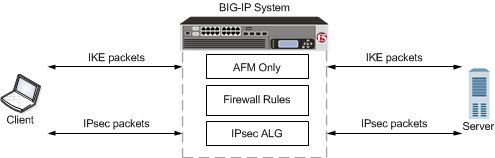
You can configure CGNAT IPsec application layer gateway (ALG) functionality with Internet Key Exchange (IKE) security for LSN source address translation. A typical IPsec ALG configuration includes a wildcard virtual server listening on Internet Security Association and Key Management Protocol (ISAKMP) port 500, using IPsec tunnel mode. When the BIG-IP system receives the first IKE packet, it picks a translation address, and, after successfully completing the IKE negotiation, creates the IKE and IPsec flows.
|
Virtual Server Configuration |
Setting |
|---|---|
|
Service Port |
|
|
Protocol |
UDP |
|
IPsecALG Profile |
Default ipsecalg profile, or custom IPsecALG profile |
|
Source Address Translation |
LSN |
|
LSN pool |
One of the following LSN pool modes applies:- NAPT
Note: The BIG-IP system must map a different translation address to each subscriber when two or more subscribers connect to the same server. However, if each subscriber connects to a different server, then each subscriber can use the same translation address, because the server IP address distinguishes the traffic. Important: If the pool of translation addresses is exhausted when a new subscriber attempts to initiate an IKE exchange with a server, the BIG-IP system logs an error and drops the IKE traffic from the second client. |
The way to dynamically negotiate security associations is to configure the Internet Key Exchange (IKE) protocol, which is included in the IPsec protocol suite. When you configure the IKE protocol, two IPsec tunnel endpoints (IKE peers) open a secure channel using an ISAKMP security association (ISAKMP-SA) to initially negotiate the exchange of peer-to-peer authentication data. This exchange is known as Phase 1 negotiation.
After Phase 1 is complete and the secure channel is established, Phase 2 negotiation begins, in which the IKE peers dynamically negotiate the authentication and encryption algorithms to use to secure the payload. Without IKE, the system cannot dynamically negotiate these security algorithms.
The IPSecALG profile provides network address translation and flow management for Internet Protocol Security (IPSec) and Internet Key Exchange (IKE) flows.
This profile enables you to specify an idle timeout value, where a connection is idle for the specified period before becoming eligible for deletion. You can also limit the number of pending Internet Key Exchange (IKE) connections, a maximum number of unacknowledged connections that a client can have, before being denied further requests, to prevent a single client from flooding all of the connections while establishing the connections. Additionally, you can apply an initial connection timeout value, which determines the maximum number of seconds to wait for a response from the server for an IKE or IPsec request.
Finally, you can configure a log publisher and logging profile for IPsec ALG functionality, as necessary, through the IPsecALG profile.
Tunnel mode causes the IPsec protocol to encrypt the entire packet (the payload plus the IP header). This encrypted packet is then included as the payload in another outer packet with a new header. Traffic sent in this mode is more secure than traffic sent in Transport mode, because the original IP header is encrypted along with the original payload.
Create a log publisher to specify where the BIG-IP system sends alert messages.
Note: If you want alerts sent to a remote syslog server, you need to create two log publishers, one for the local syslog server and one for the remote syslog server.
-
On the Main tab, click System > Logs > Configuration > Log Publishers.
The Log Publishers screen opens.
-
Click Create.
-
In the Name field, type a unique, identifiable name for this publisher.
-
For the Destinations setting, select local-syslog from the Available list, and click << to move the destination to the Selected list.
-
Click Finished.
The list of Log Publishers appears, showing the Log Publisher you just created.
-
If you want to have alerts sent to a remote syslog server, repeat steps 2-5, and at step 4 select the log destination that you created previously from the Available list.
You can create an ALG logging profile, and associate it with one or more IPsecALG profiles, to allow you to configure logging options for various events that apply to high-speed logging (HSL) destinations. A logging profile decreases the need to maintain a number of customized profiles where the events are very similar.
-
On the Main tab, click Carrier Grade NAT > Logging Profiles > ALG.
The ALG logging profiles screen opens.
-
Click Create.
The New ALG Logging Profile screen opens.
-
In the Name field, type a unique name for the logging profile.
-
From the Parent Profile list, select a profile from which the new profile inherits properties.
-
For the Log Settings area, select the Custom check box.
-
For the Log Settings area, select Enabled for the following settings, as necessary.
Setting Description CSV Format Generates log entries in comma-separated-values (csv) format. Start Control Channel Generates event log entries at the start of a control channel connection for an ALG client. End Control Channel Generates event log entries at the end of a control channel connection for an ALG client. Start Data Channel Generates event log entries at the start of a data channel connection for an ALG client. End Data Channel Generates event log entries at the end of a data channel connection for an ALG client. Inbound Transaction Generates event log entries of ALG messages triggered by an inbound connection to the BIG-IP system. Note: Enabling the CSV check box affects splunk logs because IP addresses are shown as
ip,port,rtdominstead ofip%rtdom:port. Do not mix log types and only use standard syslog formats. -
Click Finished.
The carrier-grade NAT (CGNAT) module must be enabled with the appropriate settings before you can create large-scale NAT (LSN) pools.
LSN pools are used by the CGNAT module to allow efficient configuration of translation prefixes and parameters. You can configure the following types of LSN pools:
- NAPT
- Deterministic
- PBA
- The CGNAT module must be provisioned before LSN pools can be configured.
- Before associating a LSN pool with a log publisher, ensure that at least one log publisher exists on the BIG-IP system.
Large Scale NAT (LSN) pools are used by the CGNAT module to allow efficient configuration of translation prefixes and parameters.
-
On the Main tab, click Carrier Grade NAT > LSN Pools.
The LSN Pool List screen opens.
-
Click Create.
-
In the Name field, type a unique name.
-
In the Description field, type a description.
-
Select NAPT for the pool’s translation Mode.
-
Click Finished.
Your NAPT LSN pool is now ready and you can continue to configure your CGNAT.
The CGNAT module must be provisioned before you can configure LSN pools.
Large Scale NAT (LSN) pools are used by the CGNAT module to allow efficient configuration of translation prefixes and parameters.
-
On the Main tab, click Carrier Grade NAT > LSN Pools.
The LSN Pool List screen opens.
-
Click Create.
-
In the Name field, type a unique name.
-
For the Mode setting, select Deterministic for the pool’s translation.
Note that deterministic mode does not support DS-lite tunneling or NAT64.
-
From the Log Publisher list, select the publisher that includes the destinations to which you want to send log messages.
-
In the Configuration area, for the Member List setting, type an address and a prefix length in the Address/Prefix Length field, and click Add.
If your pool uses deterministic mode, ensure that any address ranges you enter as a member do not overlap another member’s prefix address ranges. For example, the address and prefix
10.10.10.0/24overlaps10.10.10.0/23. -
For deterministic mode, the Backup Member List must have at least one member, so type an address in the Address/Prefix Length field and click Add.
-
Click Finished.
Your deterministic LSN pool is now ready, and you can continue to configure your CGNAT.
- The CGNAT module must be provisioned before LSN pools can be configured.
- Before associating a LSN pool with a log publisher, ensure that at least one log publisher exists on the BIG-IP system.
You configure Large Scale NAT (LSN) pools for the CGNAT module to use in allowing efficient configuration of translation prefixes and parameters.
-
On the Main tab, click Carrier Grade NAT > LSN Pools.
The LSN Pool List screen opens.
-
Click Create.
-
In the Name field, type a unique name.
-
In the Description field, type a description.
-
For the Mode setting, select PBA for the pool’s translation.
Note that PBA mode for DS-lite is same as for NAT44, except that all clients behind the DS-Lite tunnel are managed as one subscriber. Port block limits are in accordance with each DS-lite tunnel.
-
For the Port Block Allocation setting, specify your preferred PBA configuration.
-
In the Block Size field, type the number of ports designated for a block.
-
In the Block Lifetime field, type the number of seconds before a port block times out.
Note: If you type a timeout other than
0, you can also specify a Zombie Timeout. A Block Lifetime value that is less than the Persistence Timeout value minimizes the number of zombie port blocks. The default value of0specifies no lifetime limit and indefinite use of the port block. -
In the Block Idle Timeout field, enter the timeout (in seconds) for after the port block becomes idle.
Note: Typically, you want to use a Block Idle Timeout value less than the Persistence Timeout value, to minimize the number of zombie port blocks.
-
In the Client Block Limit field, type the number of blocks that can be assigned to a single subscriber IP address.
-
In the Zombie Timeout field, type the number of seconds before port block times out.
A zombie port block is a timed out port block with one or more active connections. The default value of
0specifies no timeout and an indefinite zombie state for the port block, as long as connections remain active. A value other than0specifies a timeout expiration, upon which existing connections are terminated, and the port block is released and returned to the pool.
-
-
In the Configuration area, for the Member List setting, type an address and a prefix length in the Address/Prefix Length field, and click Add.
-
Click Finished.
Your PBA LSN pool is now ready, and you can continue to configure your CGNAT.
You can associate an IPsecALG profile with a log publisher and logging profile that the BIG-IP system uses to send log messages to a specified destination.
-
On the Main tab, click Local Traffic > Profiles > Services > IPsecALG.
The IPsecALG profile list screen opens.
-
In the Name field, type a unique name for the profile.
-
From the Parent Profile list, select a parent profile.
-
In the Idle Timeout field, type number of seconds that a connection is idle before the connection is eligible for deletion.
-
In the Pending IKE Connection Limit field, type the maximum number of unacknowledged IKE connections that a client can send, before being denied further requests.
-
In the Initial Connection Timeout field, type the maximum number of seconds to wait for a response from the server for the IKE or IPsec request.
-
In the Log Settings area, from the Log Publisher list, select the log publisher the BIG-IP system uses to send log messages to a specified destination.
Note: If you configure a log publisher, you must also configure a Logging Profile.
Important: If you configure a log publisher to use multiple logging destinations, then, by default, all logging destinations must be available in order to log to each destination. Unless all logging destinations are available, no logging can occur. If you want to log to the available logging destinations when one or more destinations become unavailable, you must set the
logpublisher.atomicdb variable to false. -
From the Logging Profile list, select the logging profile the BIG-IP system uses to configure logging options for various ALG events.
Note: If you configure a Logging Profile, you must also configure a Log Publisher.
-
Click Finished.
You can define a virtual server that applies an IPsecALG profile and LSN pool to match IPsec ALG source (client) addresses for address translation.
-
On the Main tab, click Carrier Grade NAT > Virtual Servers.
The Virtual Server List screen opens.
-
Click Create.
The New Virtual Server screen opens.
-
In the Name field, type a unique name for the virtual server.
-
In the Description field, type a description for the virtual server.
-
From the Type list, select Standard.
-
In the Source Address field, type
0.0.0.0/0for the source address and prefix length. -
In the Destination Address/Mask field:
- If you want to specify a single IP address, confirm that the Host button is selected, and type the IP address in CIDR format.
- If you want to specify multiple IP addresses, select the Address List button, and confirm that the address list that you previously created appears in the box.
The supported format is address/prefix, where the prefix length is in bits. For example, an IPv4 address/prefix is
10.0.0.1or10.0.0.0/24, and an IPv6 address/prefix isffe1::0020/64or2001:ed8:77b5:2:10:10:100:42/64. When you use an IPv4 address without specifying a prefix, the BIG-IP system automatically uses a/32prefix.
Note: The IP address or addresses for this field must be on the same subnet as the external self-IP address.
-
In the Service Port field, type
500or select ISAKMP from the list. -
From the Configuration list, select Advanced.
-
From the Protocol list, select UDP.
-
From the IPsecALG Profile list, select a profile.
-
From the LSN Pool list, select an LSN pool.
-
Click Finished.
A virtual server is configured to use an IPsecALG profile and LSN pool to match IPsec ALG source (client) addresses for address translation.
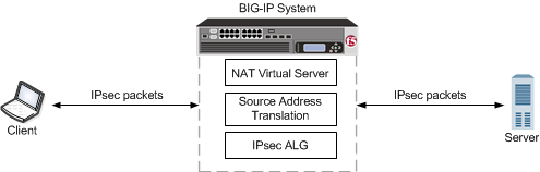
You can configure an IPsec application layer gateway (ALG) functionality with manual keys with network address translation. A typical IPsec ALG configuration includes an IPsec ESP (protocol 50) virtual server listening on port 0 (wildcard) using IPsec tunnel mode.
Note: This configuration does not provide NAT-T address translation. If you need to provide NAT-T address translation, a separate virtual server configured to use NAT-T address translation is required.
|
Virtual Server Configuration |
Setting |
|---|---|
|
Service Port |
|
|
Protocol |
|
|
IPsecALG Profile |
Default ipsecalg profile, or custom IPsecALG profile |
Tunnel mode causes the IPsec protocol to encrypt the entire packet (the payload plus the IP header). This encrypted packet is then included as the payload in another outer packet with a new header. Traffic sent in this mode is more secure than traffic sent in Transport mode, because the original IP header is encrypted along with the original payload.
Create a log publisher to specify where the BIG-IP system sends alert messages.
Note: If you want alerts sent to a remote syslog server, you need to create two log publishers, one for the local syslog server and one for the remote syslog server.
-
On the Main tab, click System > Logs > Configuration > Log Publishers.
The Log Publishers screen opens.
-
Click Create.
-
In the Name field, type a unique, identifiable name for this publisher.
-
For the Destinations setting, select local-syslog from the Available list, and click << to move the destination to the Selected list.
-
Click Finished.
The list of Log Publishers appears, showing the Log Publisher you just created.
-
If you want to have alerts sent to a remote syslog server, repeat steps 2-5, and at step 4 select the log destination that you created previously from the Available list.
You can create an ALG logging profile, and associate it with one or more IPsecALG profiles, to allow you to configure logging options for various events that apply to high-speed logging (HSL) destinations. A logging profile decreases the need to maintain a number of customized profiles where the events are very similar.
-
On the Main tab, click Carrier Grade NAT > Logging Profiles > ALG.
The ALG logging profiles screen opens.
-
Click Create.
The New ALG Logging Profile screen opens.
-
In the Name field, type a unique name for the logging profile.
-
From the Parent Profile list, select a profile from which the new profile inherits properties.
-
For the Log Settings area, select the Custom check box.
-
For the Log Settings area, select Enabled for the following settings, as necessary.
Setting Description CSV Format Generates log entries in comma-separated-values (csv) format. Start Control Channel Generates event log entries at the start of a control channel connection for an ALG client. End Control Channel Generates event log entries at the end of a control channel connection for an ALG client. Start Data Channel Generates event log entries at the start of a data channel connection for an ALG client. End Data Channel Generates event log entries at the end of a data channel connection for an ALG client. Inbound Transaction Generates event log entries of ALG messages triggered by an inbound connection to the BIG-IP system. Note: Enabling the CSV check box affects splunk logs because IP addresses are shown as
ip,port,rtdominstead ofip%rtdom:port. Do not mix log types and only use standard syslog formats. -
Click Finished.
The carrier-grade NAT (CGNAT) module must be enabled with the appropriate settings before you can create large-scale NAT (LSN) pools.
LSN pools are used by the CGNAT module to allow efficient configuration of translation prefixes and parameters. You can configure the following types of LSN pools:
- NAPT
- Deterministic
- PBA
- The CGNAT module must be provisioned before LSN pools can be configured.
- Before associating a LSN pool with a log publisher, ensure that at least one log publisher exists on the BIG-IP system.
Large Scale NAT (LSN) pools are used by the CGNAT module to allow efficient configuration of translation prefixes and parameters.
-
On the Main tab, click Carrier Grade NAT > LSN Pools.
The LSN Pool List screen opens.
-
Click Create.
-
In the Name field, type a unique name.
-
In the Description field, type a description.
-
Select NAPT for the pool’s translation Mode.
-
Click Finished.
Your NAPT LSN pool is now ready and you can continue to configure your CGNAT.
The CGNAT module must be provisioned before you can configure LSN pools.
Large Scale NAT (LSN) pools are used by the CGNAT module to allow efficient configuration of translation prefixes and parameters.
-
On the Main tab, click Carrier Grade NAT > LSN Pools.
The LSN Pool List screen opens.
-
Click Create.
-
In the Name field, type a unique name.
-
For the Mode setting, select Deterministic for the pool’s translation.
Note that deterministic mode does not support DS-lite tunneling or NAT64.
-
From the Log Publisher list, select the publisher that includes the destinations to which you want to send log messages.
-
In the Configuration area, for the Member List setting, type an address and a prefix length in the Address/Prefix Length field, and click Add.
If your pool uses deterministic mode, ensure that any address ranges you enter as a member do not overlap another member’s prefix address ranges. For example, the address and prefix
10.10.10.0/24overlaps10.10.10.0/23. -
For deterministic mode, the Backup Member List must have at least one member, so type an address in the Address/Prefix Length field and click Add.
-
Click Finished.
Your deterministic LSN pool is now ready, and you can continue to configure your CGNAT.
Sometimes a host administrator might publish a VLAN to a guest, but the guest administrator has already created, or later creates, a VLAN with the same name but with a different VLAN tag. In this case, the guest VLAN always overrides the host VLAN. The VLAN can still exist on the host (for other guests to subscribe to), but it is the guest VLAN that is used.
Whenever host and guest VLANs have the same names but different tags, traffic cannot flow between the identically-named VLANs at Layer 2. That is, when the tags do not match, the underlying Layer 2 infrastructure of the VLANs does not match, thereby preventing the host from reaching the guest.
The example here shows the tmsh command sequence for creating two separate VLANs with the same names and different tags, and the resulting traffic flow issue.
# While logged into the guest, create a VLAN:

[root@G1:/S1-green-P:Active:Standalone] config # `tmsh create net vlan *VLAN\_A* tag *1000*`

# Show that no VLANs exist on the host:

[root@host_210:/S1-green-P:Active:Standalone] config # `tmsh list net vlan all`
[root@host_210:/S1-green-P:Active:Standalone] config #

# On the host, create a VLAN with the same name as the guest VLAN but with a unique tag on the host:

[root@host_210:/S1-green-P:Active:Standalone] config # `tmsh create net vlan *VLAN\_A* tag *1001*`

# Publish the host VLAN to the guest:

[root@host_210:/S1-green-P:Active:Standalone] config # `tmsh modify vcmp guest *guest1* vlans add { *VLAN\_A* }`

# Within the guest, show that the guest still has its own VLAN only, and not the VLAN published from the host:

[root@G1:/S1-green-P:Active:Standalone] config # `tmsh list net vlan all`

   `net vlan VLAN_A {
    if-index 192
    tag 1000
    }`

# Within the guest, create a self IP address for the VLAN:

[root@G1:/S1-green-P:Active:Standalone] config # `tmsh create net self 10.1.1.1/24 vlan *VLAN\_A*`

# On the host, create a self IP address for the identically-named VLAN:

[root@host_210:/S1-green-P:Active:Standalone] config # `tmsh create net self 10.1.1.2/24 vlan *VLAN\_A*`

# From the host, open a connection to the guest, and notice that because the two VLANs have different tags, the connection fails:

[root@host_210:/S1-green-P:Active:Standalone] config # `ping -c2 10.1.1.1`

`PING 10.1.1.1 (10.1.1.1) 56(84) bytes of data.
From 10.1.1.2 icmp_seq=1 Destination Host Unreachable
From 10.1.1.2 icmp_seq=2 Destination Host Unreachable

--- 10.1.1.1 ping statistics ---
2 packets transmitted, 0 received, +2 errors, 100% packet loss, time 3000ms
pipe 2`
You can associate an IPsecALG profile with a log publisher and logging profile that the BIG-IP system uses to send log messages to a specified destination.
-
On the Main tab, click Carrier Grade NAT > ALG Profiles > IPsecALG.
The IPsecALG screen opens and displays a list of available IPsecALG profiles.
-
Click the name of an IPsecALG profile.
-
In the Idle Timeout field, type number of seconds that a connection is idle before the connection is eligible for deletion.
-
In the Pending IKE Connection Limit field, type the maximum number of unacknowledged IKE connections that a client can send, before being denied further requests.
-
In the Initial Connection Timeout field, type the maximum number of seconds to wait for a response from the server for the IKE or IPsec request.
-
In the Log Settings area, from the Log Publisher list, select the log publisher the BIG-IP system uses to send log messages to a specified destination.
Note: If you configure a log publisher, you must also configure a Logging Profile.
Important: If you configure a log publisher to use multiple logging destinations, then, by default, all logging destinations must be available in order to log to each destination. Unless all logging destinations are available, no logging can occur. If you want to log to the available logging destinations when one or more destinations become unavailable, you must set the
logpublisher.atomicdb variable to false. -
From the Logging Profile list, select the logging profile the BIG-IP system uses to configure logging options for various ALG events.
Note: If you configure a Logging Profile, you must also configure a Log Publisher.
-
Click Finished.
You can define a virtual server that applies an IPsecALG profile and LSN pool to match IPsec ALG source (client) addresses for address translation.
-
On the Main tab, click Carrier Grade NAT > Virtual Servers.
The Virtual Server List screen opens.
-
Click Create.
The New Virtual Server screen opens.
-
In the Name field, type a unique name for the virtual server.
-
In the Description field, type a description for the virtual server.
-
From the Type list, select Standard.
-
In the Source Address field, type
0.0.0.0/0for the source address and prefix length. -
In the Destination Address/Mask field:
- If you want to specify a single IP address, confirm that the Host button is selected, and type the IP address in CIDR format.
- If you want to specify multiple IP addresses, select the Address List button, and confirm that the address list that you previously created appears in the box.
The supported format is address/prefix, where the prefix length is in bits. For example, an IPv4 address/prefix is
10.0.0.1or10.0.0.0/24, and an IPv6 address/prefix isffe1::0020/64or2001:ed8:77b5:2:10:10:100:42/64. When you use an IPv4 address without specifying a prefix, the BIG-IP system automatically uses a/32prefix.
Note: The IP address or addresses for this field must be on the same subnet as the external self-IP address.
-
In the Service Port field, type
50 -
From the Configuration list, select Advanced.
-
From the Protocol list, select IPsec ESP.
-
From the IPsecALG Profile list, select a profile.
-
From the LSN Pool list, select an LSN pool.
-
Click Finished.
A virtual server is configured to use an IPsecALG profile and LSN pool to match IPsec ALG source (client) addresses for address translation.