Updated Date: 07/07/2026
Configuring BIG-IP DNS to Determine PGW Health and Availability
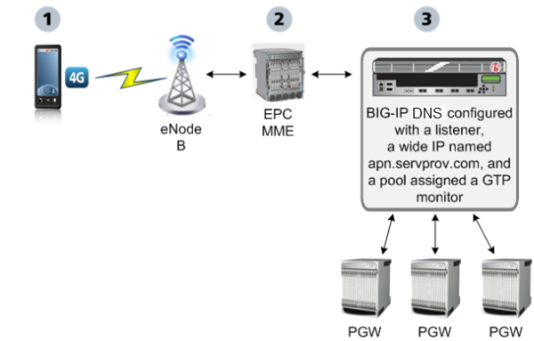
Service providers can configure the BIG-IP DNS system to increase the availability of their customer services on the System Architecture Evolution (SAE) network. One way is to configure a GTP monitor for the health and availability of a packet gateway (PGW). The GTP monitor issues an echo request to a list of PGW systems. If a PGW fails to respond to the GTP echo request, it is marked as down, and removed from the list of available PGW systems that are returned to an MME in a DNS response. BIG-IP DNS can also be configured to load balance DNS queries for the access point name (APN) across the PGW systems that are active and available.
Note: BIG-IP DNS handles only A and AAAA records for global server load balancing (GSLB).
This illustration presents a simplified depiction of how the process works on the SAE network.
-
A smartphone that is preprogrammed with an APN, for example,
apn.servprov.com, initiates a data connection. -
The EPC MME performs a DNS lookup on
apn.servprov.comin order to select a packet gateway. -
BIG-IP DNS handles the DNS request and returns only IP addresses for PGW systems that are active and available.
-
Creating a pool of packet gateway systems with an applicable pool type
On BIG-IP DNS, create a data center to contain the servers that reside on a subnet of your network.
-
On the Main tab, click DNS > GSLB > Data Centers.
The Data Center List screen opens.
-
Click Create.
The New Data Center screen opens.
-
In the Name field, type a name to identify the data center.
Important: The data center name is limited to 63 characters.
-
In the Location field, type the geographic location of the data center.
-
In the Contact field, type the name of either the administrator or the department that manages the data center.
-
From the Prober Preference list, select the preferred type of prober(s).
|
Inside Data Center |
By default, select probers inside the data center. |
|
Outside Data Center |
Select probers outside the data center. |
|
Specific Prober Pool |
Select one of the Probers from the drop-down list. When you want to assign a Prober pool at the data center level.Note: Prober pools are not used by the bigip monitor. |
- From the Prober Fallback list, select the type of prober(s) to use if insufficient numbers of the preferred type are available.
|
Any Available |
By default, select any available prober. |
|
Inside Data Center |
Select probers inside the data center. |
|
Outside Data Center |
Select probers outside the data center. |
|
None |
No fallback probers are selected. Prober fallback is disabled. |
|
Specific Prober Pool |
Select one of the Probers from the drop-down list. When you want to assign a Prober pool at the data center level. |
-
From the State list, select Enabled.
-
Click Finished.
Now you can create server objects and assign them to this data center.
Repeat these steps to create additional data centers.
Ensure that at least one data center exists in the configuration before you start creating a server.
On BIG-IP DNS, you create a server object to represent the BIG-IP DNS system itself.
-
On the Main tab, click DNS > GSLB > Servers.
The Server List screen opens.
-
Click Create.
The New Server screen opens.
-
In the Name field, type a name for the server.
Important: Server names are limited to 63 characters.
-
From the Product list, select BIG-IP System.
-
From the Data Center list, select the data center where the server resides.
-
From the Prober Preference list, select the preferred type of prober(s).
|
Inherit From Data Center |
By default, a server inherits the prober preference selection assigned to the data center in which the server resides. |
|
Inside Data Center |
A server selects the probers from inside the data center where the server resides. |
|
Outside Data Center |
A server selects the probers from outside the data center where the server resides. |
|
Specific Prober Pool |
Select one of the prober pools from the drop-down list. When assigning the prober pool at the server level.Note: Prober pools are not used by the bigip monitor. |
- From the Prober Fallback list, select the type of prober(s) to be used if insufficient numbers of the preferred type are available.
|
Inherit From Data Center |
By default, a server inherits the prober fallback selection assigned to the data center in which the server resides. |
|
Any Available |
For selecting any available prober. |
|
Inside Data Center |
A server selects probers from inside the data center where the server resides. |
|
Outside Data Center |
A server selects probers from outside the data center where the server resides. |
|
None |
No fallback probers are selected. Prober fallback is disabled. |
|
Specific Prober Pool |
Select one of the probers from the list When you want to assign a prober pool at the server level. |
-
From the State list, select Enabled.
-
For the BIG-IP System Devices setting, click Add to add a device (server).
-
Type a name in the Device Name field.
-
Type an external (public) non-floating IP address in the Address field.
-
If you use NAT, type an internal (private) IP address in the Translation field, and then click Add.
-
Click Add.
-
Click OK.
-
-
From the Configuration list, select Advanced.
Additional controls display on the screen.
-
In the Health Monitors setting, assign the
bigipmonitor to the server by moving it from the Available list to the Selected list. -
From the Availability Requirements list, select an option and enter any required values.
|
All Health Monitors |
By default, specifies that all of the selected health monitors must be successful before the server is considered up (available). |
|
At Least |
The minimum number of selected health monitors that must be successful before the server is considered up. |
|
Require |
The minimum number of successful probes required from the total number of probers requested. |
-
For the iQuery Options setting, for the TLS Minimum Version list, specify whether to use global or specific settings.
- To inherit the global setting values, retain the default (Use Global Setting).
- To select a TLS minimum version, first select Server Specific, then specify the version. The default is TLSv1.
-
For the iQuery Options setting, for the SSL Cipher List, specify whether to use global or specific settings.
- To inherit the global setting values, retain the default (Use Global Setting).
- To display the cipher string, select Server Specific. The Reset String button also displays, which allows you to get the base cipher string back in the text box.
-
From the Virtual Server Discovery list, select how you want virtual servers to be added to the system.
Important: If the virtual server IP address translation feature is going to be used, then BIG-IP DNS will automatically disable Virtual Server Discovery for the given server object globally.
|
Disabled |
The system does not use the discovery feature to automatically add virtual servers. This is the default value. Use this option for a standalone BIG-IP DNS system or for a BIG-IP DNS/LTM combo system when you plan to manually add virtual servers to the system, or if your network uses multiple route domains. |
|
Enabled |
The system uses the discovery feature to automatically add and delete virtual servers. Use this option for a BIG-IP DNS/LTM combo system when you want the BIG-IP DNS system to discover LTM virtual servers. |
|
Enabled (No Delete) |
The system uses the discovery feature to automatically add virtual servers and does not delete any virtual servers that already exist in the configuration. Use this option for a BIG-IP DNS/LTM combo system when you want the BIG-IP DNS system to discover LTM virtual servers. |
-
In the Virtual Server List setting, if you selected Disabled from the Virtual Server Discovery list, specify the virtual servers that are resources on this server.
-
In the Name field, type the name of the virtual server.
-
In the Address field, type the IP address of the virtual server.
-
From the Service Port list, select the port the server uses.
-
Click Add.
-
-
From the Link Discovery list, select how you want links to be added to the system.
|
Disabled |
The system does not use the discovery feature to automatically add links. This is the default value. Use this option for a standalone BIG-IP DNS system or for a BIG-IP DNS/LTM combo system when you plan to manually add links to the system. |
|
Enabled |
The system uses the discovery feature to automatically add and delete links. Use this option for a BIG-IP DNS/LTM combo system when you want BIG-IP DNS to discover links. |
|
Enabled (No Delete) |
The system uses the discovery feature to automatically add links and does not delete any links that already exist in the configuration. Use this option for a BIG-IP DNS/LTM combo system when you want BIG-IP DNS to discover links. |
-
Click Finished.
The Server List screen opens displaying the new server in the list.
Before you create servers to represent the packet gateway (PGW) systems, ensure there is an existing server in the BIG-IP DNS system that you are configuring.
Define the PGW systems to which BIG-IP DNS load balances access point name (APN) traffic.
-
On the Main tab, click DNS > GSLB > Servers.
The Server List screen opens.
-
Click Create.
The New Server screen opens.
-
In the Name field, type a name for the server.
Important: Server names are limited to 63 characters.
-
From the Product list, select Generic Host.
The server type determines the metrics that the system can collect from the server.
-
In the Address List area, add the IP addresses of the PGW system.
-
Type an external (public) IP address in the Address field, and then click Add.
-
If you use NAT, type an internal (private) IP address in the Translation field, and then click Add.
You can add more than one IP address, depending on how the PGW system interacts with the rest of your network.
-
-
From the Data Center list, select the data center where the server resides.
-
In the Health Monitors area, you can assign the GTP monitor to the server by moving it from the Available list to the Selected list; however, best practice is to assign the GTP monitor to the pool of PGW systems.
Tip: The GTP monitor simply checks that the PGW system responds to a GTP echo request.
-
In the Virtual Server List area, if you selected Disabled from the Virtual Server Discovery list, create a virtual server to represent (in a pool) the PGW system.
-
In the Name field, type a name for the virtual server.
-
In the Address field, type the IP address of the host server.
-
In the Service Port field, type
2152(F5 Networks recommends using this GTP-user plane tunneling data port); however, the BIG-IP system also supports the use of2123(GTP-control plane port). -
Click Add.
-
-
Click Create.
The Server List screen opens displaying the new server in the list.
Define the other PGW systems on your network.
Ensure that a self IP address exists on BIG-IP DNS that you can use as the Destination of the listener.
Create listeners to identify DNS traffic for a specific access point name (APN). The best practice is to create two listeners: one that handles UDP traffic and one that handles TCP traffic.
-
On the Main tab, click DNS > Delivery > Listeners.
The Listeners List screen opens.
-
Click Create.
The Listeners properties screen opens.
-
In the Name field, type a unique name for the listener.
-
For the Destination setting, in the Address field, type the IP address on which BIG-IP DNS listens for access point name (APN) traffic.
Note: F5 Networks recommends that you assign a unique IP address, not a self IP address.
-
In the Service area, from the Protocol list, select UDP.
-
Click Finished.
Create another listener with the same IP address, but select TCP from the Protocol list.
Ensure that you know the version of the GTP protocol that your network uses.
Create a custom GTP monitor to detect the presence and health of a packet gateway (PGW) system. The GTP monitor issues a GTP echo request, and if the PGW system fails to respond, it is automatically marked as down and removed from the available list of PGW systems that the BIG-IP system returns to an MME.
-
On the Main tab, click DNS > GSLB > Monitors.
The Monitor List screen opens.
-
Click Create.
The New Monitor screen opens.
-
In the Name field, type a name for the monitor.
-
From the Type list, select GTP.
-
From the Import Monitor list, select an existing monitor.
The new monitor inherits initial configuration values from the existing monitor.
-
In the Interval field, type a number that indicates, in seconds, how frequently the system issues the monitor check. The default is
30seconds.The frequency of a monitor check must be greater than the value of the global-level Heartbeat Interval setting. Otherwise, the monitor can acquire out-of-date data.
-
In the Timeout field, type a number that indicates, in seconds, how much time the target has to respond to the monitor check. The default is
120seconds.If the target responds within the allotted time period, it is considered up. If the target does not respond within the time period, it is considered down.
-
In the Probe Interval field, type a number that indicates the number of seconds between the probes sent by the system. The default is
1second. -
In the Probe Timeout field, type a number that indicates the number of seconds after which the system times out the probe request to the system. The default is
5seconds. -
In the Probe Attempts field, type a number that indicates the number of probes the system sends before marking the resource down. The default is
3attempts. -
In the Protocol Version field, type a number that indicates the version of the GTP protocol the system uses. The default is
1. -
For the Ignore Down Response setting, do one of the following:
- Accept the No default option.
- Select the Yes option to specify that the monitor accepts more than one probe attempt per interval.
-
Click Finished.
Now you can associate the new custom monitor with the pool that contains the GTP resources.
Tip: Associate the monitor only with the pool. If you associate the monitor with both the pool and a server, you might encounter inaccurate health check failures.
Before you can create a pool of packet gateway (PGW) systems, you need to:
- Create servers to represent the PGW systems, and manually add at least one virtual server or wide IP to each server.
- Create a GTP monitor.
You can create a pool of packet gateway systems with an applicable pool type to which the BIG-IP system can load balance global traffic.
Create an A or AAAA pool type in order to configure the BIG-IP system to load balance global traffic.
-
On the Main tab, click DNS > GSLB > Pools.
The Pool List screen opens.
-
Click Create.
The New Pool screen opens.
-
In the General Properties area, in the Name field, type a name for the pool.
Names must begin with a letter, and can contain only letters, numbers, and the underscore (_) character.
Important: The pool name is limited to 63 characters.
-
From the Type list, depending on the type of the system (IPv4 or IPv6), select either an A or AAAA pool type.
-
In the Configuration area, for the Health Monitors setting, in the Available list, select a monitor type, and move the monitor to the Selected list.
Tip: Hold the Shift or Ctrl key to select more than one monitor at a time.
-
In the Members area, for the Load Balancing Method setting, from the Preferred List, select Round Robin.
Tip: When deploying this implementation in a lab environment, to determine whether the BIG-IP system returns the DNS response that you expect, try selecting the Global Availability method and disabling the first pool member in the list.
-
From the Alternate and Fallback lists, select a static load balancing method, based on your network environment. Ensure that you select a load balancing method that does not take current server performance or connection load into account.
-
In the Members area, for the Member List setting, add virtual servers as members of this load balancing pool.
The system evaluates the virtual servers (pool members) in the order in which they are listed. A virtual server can belong to more than one pool.
-
Select a virtual server from the Virtual Server list.
-
Click Add.
-
-
Click Finished.
Create an NAPTR pool type in order to configure the BIG-IP system to load balance global traffic.
-
On the Main tab, click DNS > GSLB > Pools.
The Pool List screen opens.
-
Click Create.
The New Pool screen opens.
-
In the General Properties area, in the Name field, type a name for the pool.
Names must begin with a letter, and can contain only letters, numbers, and the underscore (_) character.
Important: The pool name is limited to 63 characters.
-
From the Type list, select the NAPTR type.
-
In the Members area, for the Load Balancing Method setting, from the Preferred List, select Round Robin.
Tip: When deploying this implementation in a lab environment, to determine whether the BIG-IP system returns the DNS response that you expect, try selecting the Global Availability method and disabling the first pool member in the list.
-
From the Alternate and Fallback lists, select a static load balancing method, based on your network environment. Ensure that you select a load balancing method that does not take current server performance or connection load into account.
-
In the Members area, for the Member List setting, from the Flags list, select a flag.
-
Add wide IPs as members of this load balancing pool.
The system evaluates the wide IPs (pool members) in the order in which they are listed. A wide IP can belong to more than one pool.
-
From the Wide IP list, select a wide IP or type a name that matches an existing wildcard wide IP.
-
In the Service field, type the name of a service or protocol.
-
Click Add.
-
-
Click Finished.
Create a SRV pool type in order to configure the BIG-IP system to load balance global traffic.
-
On the Main tab, click DNS > GSLB > Pools.
The Pool List screen opens.
-
Click Create.
The New Pool screen opens.
-
In the General Properties area, in the Name field, type a name for the pool.
Names must begin with a letter, and can contain only letters, numbers, and the underscore (_) character.
Important: The pool name is limited to 63 characters.
-
From the Type list, select the SRV type.
-
In the Members area, for the Load Balancing Method setting, from the Preferred List, select Round Robin.
Note: When you create a pool of one or more packet gateway systems (PGW) systems, it is the best practice to apply the GTP monitor and the round robin load balancing method to the pool. However, the BIG-IP system supports the use of any static load balancing method in this implementation.
Tip: When deploying this implementation in a lab environment, to determine whether the BIG-IP system returns the DNS response that you expect, try selecting the Global Availability method and disabling the first pool member in the list.
-
From the Alternate and Fallback lists, select a static load balancing method, based on your network environment. Ensure that you select a load balancing method that does not take current server performance or connection load into account.
-
In the Members area, for the Member List setting, from the Flags list, select a flag.
-
Add wide IPs as members of this load balancing pool.
The system evaluates the wide IPs (pool members) in the order in which they are listed. A wide IP can belong to more than one pool.
-
From the Wide IP list, select a wide IP or type a name that matches an existing wildcard wide IP.
-
In the Service field, type the name of a service or protocol.
-
Click Add.
-
-
Click Finished.
-
On the Main tab, click DNS > GSLB > Pools.
The Pool List screen opens.
-
Click Create.
The New Pool screen opens.
-
In the General Properties area, in the Name field, type a name for the pool.
Names must begin with a letter, and can contain only letters, numbers, and the underscore (_) character.
Important: The pool name is limited to 63 characters.
-
From the Type list, select the CNAME type.
-
In the Members area, for the Load Balancing Method setting, from the Preferred List, select Round Robin.
Note: When you create a pool of one or more packet gateway systems (PGW) systems, it is the best practice to apply the GTP monitor and the round robin load balancing method to the pool. However, the BIG-IP system supports the use of any static load balancing method in this implementation.
Tip: When deploying this implementation in a lab environment, to determine whether the BIG-IP system returns the DNS response that you expect, try selecting the Global Availability method and disabling the first pool member in the list.
-
From the Alternate and Fallback lists, select a static load balancing method, based on your network environment. Ensure that you select a load balancing method that does not take current server performance or connection load into account.
-
Add wide IPs as members of this load balancing pool.
The system evaluates the wide IPs (pool members) in the order in which they are listed. A wide IP can belong to more than one pool.
-
In the Members area, for the Member setting, from the Wide IP list, select a wide IP or type a name that matches either an existing wildcard wide IP or wide IP alias.
-
If necessary, to allow the member to point to a name that does not exist as a wide IP on DNS, select the Static Target check box.
-
Click Add.
-
-
Click Finished.
Create a MX pool type in order to configure the BIG-IP system to load balance global traffic.
-
On the Main tab, click DNS > GSLB > Pools.
The Pool List screen opens.
-
Click Create.
The New Pool screen opens.
-
In the General Properties area, in the Name field, type a name for the pool.
Names must begin with a letter, and can contain only letters, numbers, and the underscore (_) character.
Important: The pool name is limited to 63 characters.
-
From the Type list, select the MX type.
-
In the Members area, for the Load Balancing Method setting, from the Preferred List, select Round Robin.
Tip: When deploying this implementation in a lab environment, to determine whether the BIG-IP system returns the DNS response that you expect, try selecting the Global Availability method and disabling the first pool member in the list.
-
From the Alternate and Fallback lists, select a static load balancing method, based on your network environment. Ensure that you select a load balancing method that does not take current server performance or connection load into account.
-
Add wide IPs as members of this load balancing pool.
The system evaluates the wide IPs (pool members) in the order in which they are listed. A wide IP can belong to more than one pool.
-
In the Members area, for the Member setting, from the Wide IP list, select a wide IP or type a name that matches an existing wildcard wide IP.
-
Click Add.
-
-
Click Finished.
Before you configure a wide IP for an access point name (APN), ensure that a pool of packet gateway (PGW) systems is available to associate with the wide IP that you are configuring for APN load balancing.
Configure a wide IP to represent the APN for which BIG-IP DNS load balances DNS lookups across the PGW systems on your network.
-
On the Main tab, click DNS > GSLB > Wide IPs.
The Wide IP List screen opens.
-
Click Create.
The New Wide IP List screen opens.
-
In the General Properties area, in the Name field, type the APN, for example
apn.servprov.com. -
From the Type list, select one of these record types for the wide IP:
|
NAPTR |
The Name Authority Pointer record, NAPTR, aids in the standardization of Uniform Resource Names (URNs). NAPTR records map between sets of URNs, URLs and plain domain names, and suggest to clients the protocols available for communication with the mapped resource. |
|
A |
The Address record, or A record, lists the IP address for a given host name. |
|
SRV |
The Service resource record, SRV, is a pointer with which an alias for a given service is redirected to another domain. |
|
CNAME |
The Canonical Name resource record, CNAME, specifies an alias or nickname for the official, or canonical, host name. |
|
AAAA |
The IPv6 Address record, or AAAA record, lists the 128-bit IPv6 address for a given host name. |
|
MX |
The Mail Exchange resource record, MX, defines the mail system(s) for a given domain. |
-
In the Pools area, from the Load Balancing Method list, select Round Robin.
-
From the Pool list, select the pool of PGW systems, and then click Add.
-
Click Finished.