Updated Date: 07/07/2026
Configuring Diameter Load Balancing and Message Routing
The Diameter protocol provides message-routing functionality that the BIG-IP system supports in a load-balancing configuration.
In a message routing configuration, the BIG-IP system manages requests and responses among peers. The following illustration shows a Diameter routing configuration with requests from Client 1 and Client 2 to servers located in different destination realms, Realm-A and Realm-B.
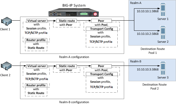
A typical Diameter message routing configuration with two realms involves configuring the following items.
| Functionality | Description |
|---|---|
| Pool | A pool for each realm directs Diameter traffic to servers. |
| Session profile | A session profile for each realm configures a session as a set of messages between two Diameter nodes on behalf of a user. |
| Transport configuration | An optional transport configuration for each realm defines how the BIG-IP system connects with the servers on your network when routing messages. You can assign a transport configuration to a virtual server or peer, as needed. |
| Peer | The MRF peer object is a logical grouping of Diameter devices implementing a common function. The peer object specifies the set of devices via a pool and the parameters needed to connect to the devices via a transport-config. |
| Static Route | Each static route specifies a set of peers in a destination realm to use in forwarding messages. In this example, Realm-A includes Peer 1 , and Realm-B includes Peer 2. |
| Router profile | A router profile configures Diameter message routing parameters and static routes to be used by a virtual server in routing Diameter messages. |
| Virtual server | Defines a listener to receive Diameter messages and details on how to forward messages to other Diameter devices. |
The Diameter session profile includes Diameter protocol parameters that can be used by a virtual server or transport configuration in managing Diameter traffic. The profile enables you to configure the properties of a Diameter session as a set of messages between two diameter nodes on behalf of a user. Note that those same two diameter nodes can also include multiple active user sessions. The session profile provides you with parameters to configure settings for timeout, watchdog failures, and message-size, as well as persistence, rewrite, and capabilities-handshake functionality.
| Functionality | Description |
|---|---|
| Settings | Configure timeout functionality, watchdog failures, and message size. |
| Persistence | Configure persistence functionality, including a type, AVP, and timeout. |
| Rewrite | Provide AVP rewriting to conceal clients from servers, as well as to conceal servers from clients. |
| Capabilities Handshake | When the Diameter session profile is configured as a proxy, the BIG-IP system generates capabilities-exchange messages, sending a Capabilities-Exchange-Request (CER) and responding with a Capabilities-Exchange-Answer (CEA), to establish a diameter session with connected nodes. |
You can apply different session profiles to different transport configurations, and then apply the different transport configurations to different message routing peers, which point to different physical pools. You can also apply different session profiles by applying one session profile to the transport configuration, and a different session profile to the virtual server.
A message routing peer defines how the BIG-IP system routes messages to destination hosts. When you configure a message routing peer, you define a pool of destination hosts, and a connection method for them, an optional transport configuration configured with a Diameter session profile, as needed, the number of connections to a destination host, and a ratio value for selection of a peer. After defining the peers, you can use those peers in configuring static routes.
When an inband monitor is assigned to a Diameter message routing pool, the inband monitor marks a pool member down when the total failures from the pool member exceeds or equals the maximum number of failures configured. When a pool member is marked down, the connection remains alive, but load balancing functions only among the remaining pool members within the same pool. The active Diameter monitor marks the pool member up when service is restored.
If a peer does not specify a pool, the BIG-IP system uses the destination IP address and port of the ingress message’s connection. If a peer specifies a pool without pool members, the message is unroutable.
When you configure a message routing peer to use a transport configuration, you can enable that peer to use auto-initialization functionality, which automatically creates outbound connections to active pool members in the peer’s specified pool. In order for the auto-initialization functionality to work, you need to specify the peer in a static route, and then specify that static route in a router profile that is assigned to a message routing virtual server, The BIG-IP system automatically initiates a connection for each router profile that contains the peer. You enable auto-initialization functionality for a peer by selecting the Auto-Initialization Enabled check box. Additionally, you can specify an Auto-Initialization Interval value, which compensates for latency, to verify the connection between the BIG-IP system and pool members (ranging from 500ms through 65535ms, with a default value of 5000ms). If a connection does not exist, auto-initialization functionality attempts to reestablish a connection.
If a peer does not specify a transport configuration, the BIG-IP system uses the transport type of the message’s originating connection.
When you configure a Diameter static route, the BIG-IP system provides two modes for peer selection: sequential and ratio.
In sequential mode, the BIG-IP system uses peers in the order specified by the Peers Selected list. If a message is retried, the next peer in the Peers Selected list is used.
In ratio mode, the BIG-IP system uses peers in accordance with the peer’s ratio value, which you specify when configuring each peer. The relative ratio value for each peer determines whether a peer is selected from the list. For example, a peer with a ratio value of 1 is typically selected over a peer with a ratio value of 2. The lower the ratio value, the greater the probability for selection.
Before configuring a mode for peer selection, you must first configure each peer, using the Peer tab, to include peers in the Available list.
In the rare instance when a Diameter peer connects to the BIG-IP system, and the BIG-IP system simultaneously initiates a connection to that peer, the BIG-IP system resolves the connection conflict by means of an election process. The BIG-IP system uses an algorithm that evaluates and resolves which connection to use (whereupon the election winner drops the unused connection), based on the Origin-Host Attribute-Value Pair (AVP).
This election process is enabled only when the Diameter peer Connection Mode is set to Per Peer and the Number of Connections value equals 1.
In an active-standby configuration, the election process runs only on the active device. If mirroring is enabled, the used connection is mirrored on the standby device.
You can examine the election process results in the Diameter log files. The following examples show typical log messages for the election process.
| Condition | Message |
|---|---|
| Election process results | DIAMETER: Election process won | lost between peer peer-host-name and big-ip-host-name. |
| Closing outgoing connection due to winning election | DIAMETER: Closing outgoing connection to ip:port-id closed by election process. |
The message routing functionality Static Routes enables you to configure a route that specifies a set of peers to use in forwarding messages. When you configure a static route, you can specify an application ID, destination realm, origin realm, virtual server, peer selection mode, and peers.
The required static route attributes (each of which must match the respective request parameter) are prioritized in this order:
- Destination Realm
- Application Id
- Origin Realm
- Virtual Server
A static route is a default route when each of these attributes is set to the default (wildcard) value.
With the Diameter router profile, you can configure Diameter routing parameters to be used by a virtual server in routing Diameter messages. When you configure a Diameter router profile, you can specify persistence, rewrite, and capabilities-handshake functionality.
A Diameter proxy and router implementation can mirror client and server connections.
In a high-availability configuration, the active device mirrors connections (including auto-initialization connections) on the standby device, creating and maintaining the same state on each device. The standby device, however, does not route the messages. Instead the standby device stores the messages until the active device notifies the standby device that the message has been routed. This enables the standby device to deliver the message to the equivalent connection for egress processing. A sweeper drops the messages if the standby device stores them longer than the specified value. Enabling this setting ensures a higher level of connection reliability, but it can also affect system performance. As the mirrored messages flow though the client-side connection, normal ingress iRule events and routing occur.
This list specifies supported Diameter Attribute-Value Pair (AVP) names.
ACCOUNTING-REALTIME-REQUIREDACCOUNTING-RECORD-NUMBERACCOUNTING-RECORD-TYPEACCOUNTING-SUB-SESSION-IDACCT-APPLICATION-IDACCT-INTERIM-INTERVALACCT-MULTI-SESSION-IDACCT-SESSION-IDAUTH-APPLICATION-IDAUTH-GRACE-PERIODAUTH-REQUEST-TYPEAUTH-SESSION-STATEAUTHORIZATION-LIFETIMECALLING-STATION-IDCLASSDESTINATION-HOSTDESTINATION-REALMDISCONNECT-CAUSEE2E-SEQUENCEERROR-MESSAGEERROR-REPORTING-HOSTEVENT-TIMESTAMPEXPERIMENTAL-RESULTEXPERIMENTAL-RESULT-CODEFAILED-AVPFIRMWARE-REVISIONFRAMED-IP-ADDRESSHOST-IP-ADDRESSINBAND-SECURITY-IDMULTI-ROUND-TIME-OUTORIGIN-HOSTORIGIN-REALMORIGIN-STATE-IDPRODUCT-NAMEPROXY-HOSTPROXY-INFOPROXY-STATERE-AUTH-REQUEST-TYPEREDIRECT-HOSTREDIRECT-HOST-USAGEREDIRECT-MAX-CACHE-TIMERESULT-CODEROUTE-RECORDSESSION-BINDINGSESSION-IDSESSION-SERVER-FAILOVERSESSION-TIMEOUTSUBSCRIPTION-IDSUBSCRIPTION-ID-DATASUBSCRIPTION-ID-TYPESUPPORTED-VENDOR-IDTERMINATION-CAUSEUSER-EQUIPMENT-INFOUSER-EQUIPMENT-TYPEUSER-EQUIPMENT-VALUEUSER-NAMEVENDOR-IDVENDOR-SPECIFIC-APPLICATION-ID
Complete these tasks to configure Diameter message routing on a BIG-IP system.
In a basic Diameter message routing configuration, you can define a routing pool that contains Diameter servers as its members.
-
On the Main tab, click Local Traffic > Pools.
The Pool List screen opens.
-
Click Create.
The New Pool screen opens.
-
In the Name field, type a unique name for the pool.
-
Using the New Members setting, add each resource that you want to include in the pool:
-
(Optional) In the Node Name field, type a name for the node portion of the pool member.
-
In the Address field, type an IP address.
-
In the Service Port field, type a port number, or select a service name from the list.
-
(Optional) In the Priority field, type a priority number.
-
Click Add.
-
-
Click Finished.
The pool is configured to manage Diameter servers as pool members.
You can create a Diameter session profile to specify protocol parameters, as necessary.
-
On the Main tab, click Local Traffic > Profiles > Message Routing > Diameter.
The Diameter Session Profiles list screen opens.
-
Click Create.
The New Diameter Session Profile screen opens.
-
Type a unique Name for the diameter session profile.
-
Select a Parent Profile from which the new profile inherits properties.
-
Add a description:
-
In the General Properties area, at the far right of Description, select the check box.
-
Type a Description.
-
-
At top right of the Settings area, select the Custom check box to enable editing, and specify the following settings.
-
For Dynamic Route Insertion, select the check box to create a dynamic route for the connection.
-
For Dynamic Route Lookup , select the check box to have a previously created dynamic route consulted when routing a message.
-
For Loop Detection, select the Enabled check box for insertion of route-record AVP and also rejection of looped messages.
-
In the Handshake Timeout box, type the number of seconds before the handshake to a peer times out.
-
For Maximum Watchdog Failures, type the maximum number of device watchdog failures that the traffic management system can receive before it tears down the connection.
Note: If the number of device watchdog failures exceeds the specified value, and the Reset on Timeout check box is selected, then the connection will be reset. If the number of device watchdog failures is greater than three times the specified value, the connection will be reset, even if the Reset on Timeout check box is cleared.
-
Select the Reset on Timeout check box to reset the connection when watchdog failures exceed the specified number of maximum watchdog failures.
-
In the Watchdog Timeout box, type the number of seconds that a client-side or server-side connection can be idle before a device watchdog request (DWR) is sent.
Note: The default value of
0prevents sending a DWR. -
From the Disconnect Peer Action list, select an action type that specifies the state of a peer based on the Disconnect-Peer-Request (DPR) received from the peer.
Setting Description None Terminates the connection from receiving a DPR. You can re-establish a connection between the peer and the BIG-IP system. This is the default. Disabled A node continues to process persistent and active connections. A node can accept new connections only if the connections belong to an existing persistent session. Forced Offline A node allows existing connections to time out. No new connections are allowed. -
In the Maximum Message Size box, type the maximum number of bytes allowed for a message.
-
-
For the Persistence area, select the Custom check box and specify the following settings.
-
From the Persist Type list, select a type of persistence.
Setting Description None Disables persistence. AVP Enables persistence as determined by the AVP within the message. Custom Enables persistence as determined by a custom key specified within an iRule. -
For Persist AVP, type an expression for the session-key that identifies the Diameter AVP.
-
For Persist Timeout, type a timeout value for persistence entries in seconds.
-
-
For the Rewrite area, select the Custom check box and specify the following settings.
-
For Origin Host Rewrite, type a value to use in rewriting the Origin-Host AVP on egress.
Note: This value applies to all Diameter messages and can override specified Capabilities Handshake AVP values.
-
For Origin Realm Rewrite, type a value to use in rewriting the Origin-Realm AVP on egress.
Note: This value applies to all Diameter messages and can override specified Capabilities Handshake AVP values.
-
For Destination Host Rewrite, type a value to use in rewriting the Destination-Host AVP on egress.
-
For Destination Realm Rewrite, type a value to use in rewriting the Destination-Realm AVP on egress.
-
-
For the Capabilities Handshake area, select the Custom check box and specify the following settings.
Note: You must configure these settings to initiate Capabilities-Exchange-Request (CER) handshake requests to downstream peers, as well as to provide Capabilities-Exchange-Answer (CEA) responses to upstream peers within Device-Watchdog-Request (DWR), Device-Watchdog-Answer (DWA), Disconnect-Peer-Request (DPR), and Disconnect-Peer-Answer (DPA) messages.
-
In the Origin Host box, type an identifier for the originating server, for example,
siteserver.f5.com.If the Origin Host setting is not specified, the BIG-IP system host is used.
-
In the Origin Realm box, type an identifier for the originating realm, for example,
f5.If the Origin Realm setting is not specified, the BIG-IP system realm is used.
-
In the Vendor ID box, type the vendor identification number assigned to the diameter server by the Internet Assigned Numbers Authority (IANA).
Note: You can use a vendor-specific
vendor-id,auth-application-id, oracct-application-id. -
For Product Name, type a vendor-assigned name for the product.
-
For Authentication Application ID, type the AAA identifier for a specific application.
-
For Accounting Application ID, type the accounting identifier for a specific application.
-
-
For the Retransmission area, select the Custom check box and specify the following settings.
-
From the Retransmission Action list, select an action to take when retransmission is triggered for a request message.
Setting Description Disabled Disables retransmission functionality. Busy Sends back a response to the client with the error DIAMETER_TOO_BUSY (3004). Unable Sends back a response to the client with the error DIAMETER_UNABLE_TO_DELIVER (3002). Retransmit Retransmits the original request message. The destination chosen depends on the message routing persistence and route lookup. By default (unless iRules are used), the message is resent to the same peer again. The Diameter error may then have to be transitory (that is, 4*** Error Code) for retransmission to be beneficial. -
For Retransmission Timeout, type the number of seconds the message routing framework (MRF) will wait before retransmitting if no response is received. The default is
5seconds. -
In the Array of Retransmission Result Codes box, type a number that specifies the error response RESULT-CODES, which can trigger a retransmission action like retransmission.
-
In the Retransmission Queue Maximum Messages box, type a number for the the maximum number of messages that may be held in the retransmission queue.
Note: If a request message is received that is enabled for retransmission, and the retransmission queue has reached its configured limit, a busy answer (DIAMETER_TOO_BUSY) is returned to the originator.
-
In the Retransmission Queue Maximum Bytes box, type the maximum number of bytes that may be held in the retransmission message queue.
Note: If a request message is received that is enabled for retransmission, and the retransmission queue has reached its configured limit, a busy answer (DIAMETER_TOO_BUSY) is returned to the originator.
-
In the Retransmission Queue Low Limit box, type a number that specifies, in percent, the low-water mark for the retransmission queue.
Note: When the queue drops below the Retransmission Queue Low Limit, the TCP window reopens. This happens by default at a 60% queue depth.
-
In the Retransmission Queue High Limit box, type a number that specifies in percent, the high-water mark for the retransmission queue.
Note: When the Retransmission Queue High Limit is exceeded, the TCP window starts closing. This happens by default at a 90% queue depth.
-
-
For the SNMP Trap Thresholds area, select the Custom check box and specify the following settings.
-
In the Peer Delay Critical Limit box, type a number that specifies the peer delay critical limit. The default is
0, which disables the limit. -
In the Peer Errors Major Threshold box, type a number that specifies the peer errors major threshold. The default is
75. -
In the Peer Timeouts Major Threshold box, type a number that specifies the peer timeouts major threshold. The default is
75. -
In the Egress Critical Message Rate Limit box, type a number that specifies the egress critical message rate limit. The default is
0, which disables the limit. -
In the Egress Major Message Rate Limit box, type a number that specifies the egress major message rate limit. The default is
0, which disables the limit. -
In the Ingress Critical Message Rate Limit box, type a number that specifies the ingress critical message rate limit. The default is
0, which disables the limit. -
In the Ingress Major Message Rate Limit box, type a number that specifies the ingress major message rate limit. The default is
0, which disables the limit.
-
-
Click Finished.
Before you can create a diameter transport config, you must ensure that at least one Diameter session profile exists in the BIG-IP® system configuration.
Create a transport config to define how the BIG-IP system connects with the servers on your network when routing and load balancing Diameter messages.
-
On the Main tab, click Local Traffic > Profiles > Message Routing > Diameter.
The Diameter Session Profiles list screen opens.
-
On the menu bar, click Transport Config.
The Diameter screen opens.
-
Click Create.
The New Transport Config screen opens.
-
Type a unique Name for the transport configuration.
-
For the Profiles setting, move both a transport protocol profile (TCP, UDP, or SCTP) and a Diameter session profile from the Available list to the Selected list.
You can only associate one protocol profile and one session profile with each transport configuration.
-
For the iRules setting, select an iRule from the Available list, and move it to the Selected list.
-
In the Source Port box, type the number of the port this transport configuration uses to connect to the servers on your network.
-
In the Source Port Mode field, select how the system should select a source port for the outgoing connection. The default is Change.
|
Option |
Description |
|---|---|
|
Change |
The system selects an ephemeral source port for the outgoing connection. |
|
Preserve |
If the value of source port for the outgoing connection is specified, then the system attempts to use. Otherwise attempts to preserve the source port of the incoming connection. |
|
Preserve Strict |
If the value of source port is specified, then the system forces the outgoing connection to use it. Otherwise, forces the new connection to preserve the source port of the incoming connection. The system fails to create a new outgoing connection if the specified source port is already in use. |
- From the Source Address Translation list, select an option to define how this transport configuration implements selective and intelligent source address translation. The default is Auto Map.
|
Option |
Description |
|---|---|
|
SNAT |
The system uses the specified SNAT pool for source address translation. |
|
Auto Map |
The system uses the self IP addresses of BIG-IP system as the translation addresses. |
|
None |
The system does not translate source addresses. |
- Click Finished.
In order to create a peer, you must first ensure that at least one transport configuration and one pool exist in the BIG-IP system configuration.
You create a peer to define how the BIG-IP system connects with the servers on your network, and to which servers the system routes and load balances messages.
-
On the Main tab, click Local Traffic > Profiles > Message Routing > Diameter.
The Diameter Session Profiles list screen opens.
-
On the menu bar, click Peers.
The Peers list screen opens.
-
Click Create.
The New Peer screen opens.
-
Type a unique Name for the peer.
-
Type a Description of the peer.
-
From the Connection Mode list, select an option to specify how connections are distributed to a remote host.
Option Description Per Blade The number of connections is distributed and controlled per blade on a VIPRION system. Per Peer (Default) The number of connections to a remote host is per peer. Per TMM The number of connections to a remote host is per TMM on the BIG-IP system. Per Client The number of connections to a remote host is per client connection. Responses are delivered to the connection initiating the request. This option is typically used when implementing a firewall, because of its restrictive functionality. Note: The configured Connection Mode, Number of Connections, and Ratio settings determine how the BIG-IP system uses connections to pool members in delivering messages.
-
From the Pool list, select the pool of servers to which the system load balances Diameter messages.
In the case where the calls should be always sent to a single SIP Server, you still need to create a pool with a single member (the SIP Server) and add the same to the peer.
-
From the Transport Config list, select the transport configuration that defines the egress message routing peer connection.
-
In the Number of Connections box, type the number of allowed connections between the BIG-IP system and the servers in the selected pool.
-
For Ratio, type the ratio assigned to this peer for use within a static route.
-
If you want to automatically create outbound connections to active pool members in the peer’s specified pool, select the check box (enabled) for Auto-Initialization Enabled.
-
In the Auto-Initialization Interval box, type a number, in milliseconds, to specify the time interval the BIG-IP checks for a connection to a pool member.
-
Click Finished.
The peer can now determine how the BIG-IP system connects with the servers on your network, and to which servers the system routes and load balances messages.
Ensure that at least one peer and one virtual server exist in the BIG-IP system configuration.
Create a static route when you want to route proxiable messages from specific clients to specific domains, and load balance those messages across a group of peers. If the configured attributes of a static route match the attributes in a message, the system forwards the message to a member of the pool associated with one of the peers.
Note: The BIG-IP system can use multiple session profiles in a single routing instance, because a different profile can be associated with each member of a pool.
-
On the Main tab, click Local Traffic > Profiles > Message Routing > Diameter.
The Diameter Session Profiles list screen opens.
-
On the menu bar, click Static Routes.
The static routes list screen opens.
-
Click Create.
The New Route screen opens.
-
Type a unique Name for the static route.
-
Type a Description.
-
For Application ID, type the identifier matching the application-id in the Diameter message. A value of
0matches every application-id. -
In the Destination Realm box, type the destination realm matching the Destination-Realm AVP value in the message.
Note: A blank value routes all destination-realms.
-
In the Origin Realm box, type the origin realm matching the Origin-Realm AVP value in the message.
Note: A blank value routes all origin-realms.
-
From the Virtual Server list, select the virtual server from which the system receives client requests for this static route.
If you do not select a virtual server, the system uses this static route to route messages originating from any client.
-
From the Peer Selection Mode list, select an option to specify how the system selects the Peer to route a message to:
Option Description Ratio Peer selection is based on the ratio that is set for each peer in the Selected list. Sequential Peer selection is based on the order of the peers in the Selected list. -
For the Peers setting, move, from the Available list to the Selected list, the peers that define the servers to which the system load balances or routes messages.
Note: Entries in the Selected list are not prioritized; consequently, the order of items appearing in the list is not enforced.
-
Click Finished.
A static route is configured to route messages from specific clients to specific domains.
You can create a Diameter Router profile to route traffic as specified.
-
On the Main tab, click Local Traffic > Profiles > Message Routing > Diameter.
The Diameter Session Profiles list screen opens.
-
On the menu bar, click Router Profiles.
The Router Profiles list screen opens.
-
Click Create.
The New Diameter Router Profile screen opens.
-
Type a unique Name for the diameter session profile.
-
From the Parent Profile list, select a profile from which the new profile inherits properties.
-
For the Description setting, select the check box at the right, and type a description in the box.
-
At the top of the Settings area, select the Custom check box.
-
For the Use Per-Message iRule Scope setting, select the check box to specify iRule events are scoped to the message executing.
The default, disabled, is when all Diameter iRule events are scoped to the connection flow; all share a single execution context per flow.
-
Select the Use Local Connection check box to specify that connections established by the ingress TMM are preferred to connections that are established by another TMM when selecting an egress connection to a destination peer.
-
In the Maximum Pending Messages box, type the maximum number of pending messages held while waiting for a connection to a peer to be created.
Note: If the specified value is reached, any additional messages to the peer will be undeliverable, and held messages are delivered to the peer.
-
In Maximum Pending Bytes, type the maximum number of bytes contained within pending messages that will be held while waiting for a connection to a peer to be created.
Note: If the specified value is reached, any additional messages to the peer will be undeliverable, and held messages are delivered to the peer.
-
For use with connection mirroring, specify the Traffic Group setting:
-
Clear the Inherit traffic group from current partition / path check box.
-
From the list, select a traffic group, such as, traffic-group-1.
Important: Changing traffic groups with Connection Mirroring enabled drops all mirrored connections and loses all persistence data. If you change traffic groups, mirroring must restart.
-
-
Select the Connection Mirroring check box.
Note: For connection mirroring to properly function, this device must be a member of a device group.
-
In the HA Message Sweeper Interval box, type a value (in milliseconds) for the frequency of the mirrored message sweeper.
-
In Transaction Timeout, type the maximum number of seconds the system allows for a transaction, that is, the time between a request and response.
Note: When the system receives a provisional response, the timer restarts.
-
For the Static Routes setting, select a static route from the Available list, and move it to the Selected list.
-
Click Finished.
-
In the Statistics Collection Settings area, for the Per Peer Stats Collection setting, select the check box to enable capturing profile-specific stats per pool member.
The Diameter Router profile is configured to route traffic, as you have specified.
The final task in configuring Diameter message routing for load balancing is to define a virtual server that references the custom Diameter profile and Router profile that you created in previous tasks.
-
On the Main tab, click Local Traffic > Virtual Servers.
The Virtual Server List screen opens.
-
Click Create.
The New Virtual Server screen opens.
-
In the Name field, type a unique name for the virtual server.
-
From the Type list, select Message Routing.
-
For the Destination Address/Mask setting, confirm that the Host button is selected, and type the IP address in CIDR format.
The supported format is address/prefix, where the prefix length is in bits. For example, an IPv4 address/prefix is
10.0.0.1or10.0.0.0/24, and an IPv6 address/prefix isffe1::0020/64or2001:ed8:77b5:2:10:10:100:42/64. When you use an IPv4 address without specifying a prefix, the BIG-IP system automatically uses a/32prefix.Note: The IP address you type must be available and not in the loopback network.
-
In the Service Port field, type
3868. -
From the Configuration list, select Advanced.
-
From the Application Protocol list, select Diameter.
-
From the Session Profile list, select a Diameter session profile.
Note: You can specify a different session profile, as needed, when configuring the transport configuration that is assigned to a peer.
-
From the Router Profile list, select a Diameter router profile.
-
Click Finished.
The virtual server that references the Diameter session profile and Router profile appears in the Virtual Server list.
You can configure the BIG-IP system to monitor pool member health using a Diameter monitor. Use a Diameter monitor to check the health of a host with an active Diameter session. The Diameter monitor also monitors a Diameter connection independently of a specific Diameter session and marks a host that had been marked down, but is online again, as available.
After you create a Diameter profile, you can create a custom Diameter monitor. The purpose of the Diameter monitor is to monitor the health of all servers running the Diameter service.
-
On the Main tab, click Local Traffic > Monitors.
The Monitors List screen opens.
-
Click Create.
The New Monitor screen opens.
-
In the Name field, type a name for the monitor.
-
From the Type list, select Diameter.
The screen refreshes, and displays the configuration options for the Diameter monitor type.
-
Configure additional settings based on your network requirements.
-
Click Finished.
Add health monitors to a pool when you want the BIG-IP system to monitor the health of the pool members. Repeat this procedure for each desired pool.
-
On the Main tab, click Local Traffic > Pools.
The Pool List screen opens.
-
Click the name of the pool you want to modify.
-
For the Health Monitors setting, in the Available list, select a monitor type, and click << to move the monitor to the Active list.
Tip: Hold the Shift or Ctrl key to select more than one monitor at a time.
-
Click Finished.
The new pool appears in the Pools list.
You can view statistics for Diameter sessions and routes.
Ensure that a Diameter session profile is assigned to at least one virtual server.
When you want to see how the BIG-IP system is handling Diameter communications, you can view statistics per Diameter session profile.
-
On the Main tab, click Statistics > Module Statistics > Local Traffic.
The Local Traffic statistics screen opens.
-
From the Statistics Type list, select Profiles Summary.
-
In the Details column for the Diameter Session profile, click View to display detailed statistics about Diameter sessions.
Ensure that at Diameter router profile is assigned to at least one virtual server.
When you want to see how the BIG-IP system is handling Diameter message routing, you can view statistics per Diameter router profile.
-
On the Main tab, click Statistics > Module Statistics > Local Traffic.
The Local Traffic statistics screen opens.
-
From the Statistics Type list, select Profiles Summary.
-
In the Details column for the Diameter Router profile, click View to display detailed statistics about the routing of Diameter messages.