Updated Date: 07/07/2026
Configuring a One-IP Network Topology
One configuration option you can use with the BIG-IP system is a one-IP network topology. This differs from the typical two-network configuration in two ways:
- Because there is only one physical network, this configuration does not require more than one interface on the BIG-IP system.
- Clients need to be assigned SNATs to allow them to make connections to servers on the network in a load balancing pool.
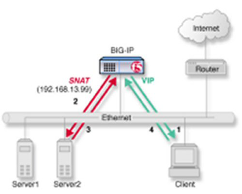
Part of this configuration requires you to configure the BIG-IP system to handle connections originating from the client. You must define a SNAT in order to change the source address on the packet to the SNAT external address, which is located on the BIG-IP system. Otherwise, if the source address of the returning packet is the IP address of the content server, the client does not recognize the packet because the client sent its packets to the IP address of the virtual server, not the content server.
If you do not define a SNAT, the server returns the packets directly to the client without giving the BIG-IP system the opportunity to translate the source address from the server address back to the virtual server. If this happens, the client might reject the packet as unrecognizable.
The single interface configuration is shown in the following illustration.
Verify that all content servers for the pool are in the network of VLAN external.
For a basic configuration, you need to create a pool to manage HTTP connections. This pool enables SNATs for any connections destined for a member of the pool.
-
On the Main tab, click Local Traffic > Pools.
The Pool List screen opens.
-
Click Create.
The New Pool screen opens.
-
In the Name field, type a unique name for the pool.
-
For the Health Monitors setting, from the Available list, select the http monitor and move the monitor to the Active list.
-
For the Allow SNAT setting, verify that the value is Yes.
-
In the Resources area of the screen, use the default values for the Load Balancing Method and Priority Group Activation settings.
-
Using the New Members setting, add each resource that you want to include in the pool:
-
Type an IP address in the Address field.
-
Type
80in the Service Port field, or select HTTP from the list. -
(Optional) Type a priority number in the Priority field.
-
Click Add.
-
-
Click Finished.
The new pool appears in the Pools list.
This task creates a destination IP address for application traffic. As part of this task, you must assign the relevant pool to the virtual server.
-
On the Main tab, click Local Traffic > Virtual Servers.
The Virtual Server List screen opens.
-
Click Create.
The New Virtual Server screen opens.
-
In the Name field, type a unique name for the virtual server.
-
For the Destination Address/Mask setting, confirm that the Host button is selected, and type the IP address in CIDR format.
The supported format is address/prefix, where the prefix length is in bits. For example, an IPv4 address/prefix is
10.0.0.1or10.0.0.0/24, and an IPv6 address/prefix isffe1::0020/64or2001:ed8:77b5:2:10:10:100:42/64. When you use an IPv4 address without specifying a prefix, the BIG-IP system automatically uses a/32prefix.Note: The IP address you type must be available and not in the loopback network.
-
In the Service Port field, type
80, or select HTTP from the list. -
From the HTTP Profile list, select http.
-
In the Resources area of the screen, from the Default Pool list, select the relevant pool name.
-
Click Finished.
You now have a virtual server to use as a destination address for application traffic.
Another task that you must perform to implement one-IP network load balancing is to define a default route for the VLAN external.
-
On the Main tab, click Network > Routes.
-
Click Add.
The New Route screen opens.
-
In the Name field, type
Default Gateway Route. -
In the Destination field, type the IP address
0.0.0.0.An IP address of
0.0.0.0in this field indicates that the destination is a default route. -
From the Resource list, select Use VLAN/Tunnel.
A VLAN represents the VLAN through which the packets flow to reach the specified destination.
-
Select external from the VLAN/Tunnel list.
-
Click Finished.
The default route for VLAN external is defined.
To configure the BIG-IP system to handle connections originating from the client, you can define a SNAT to change the source address on the packet to the SNAT external address located on the BIG-IP system.
-
On the Main tab, click Local Traffic > Address Translation.
The SNAT List screen displays a list of existing SNATs.
-
Click Create.
-
Name the new SNAT.
-
In the Translation field, type the IP address that you want to use as a translation IP address.
-
From the Origin list, select Address List.
-
For each client to which you want to assign a translation address, do the following:
-
In the Address field., type a client IP address.
-
Click Add.
-
-
From the VLAN/Tunnel Traffic list, select Enabled on.
-
For the VLAN List setting, in the Available field, select external, and using the Move button, move the VLAN name to the Selected field.
-
Click the Finished button.
The BIG-IP system is configured to handle connections originating from the client
You must configure a client SNAT before you can configure ephemeral port exhaustion functionality for that SNAT.
You can configure the BIG-IP system to accumulate real-time ephemeral-port statistics, and when usage exceeds a specified threshold level, to log an error and provide a Simple Network Management Protocol (SNMP) alert notification. Thus you can assess an approaching exhaustion of ephemeral ports, and respond accordingly.
-
Log on to the command line of the system using the
rootaccount. -
Type
tmshto access the Traffic Management Shell. -
Type the following command to enable ephemeral port-exhaustion threshold warning functionality. The default value is
enabled.modify ltm global-settings traffic-control port-find-threshold-warning [enabled_or_disabled] -
Type the following command to specify the number of random attempts to find an unused outbound port for a connection. Values can range from
1through12. The default value is8.modify ltm global-settings traffic-control port-find-threshold-trigger [threshold_level] -
Type the following command to specify the timeout period, in seconds, from one threshold trigger until a subsequent threshold trigger, which if exceeded, resets and causes the threshold warning to expire. Values can range from
0through300seconds. The default value is30.modify ltm global-settings traffic-control port-find-threshold-timeout [timeout_period]
The BIG-IP system is configured to accumulate real-time ephemeral-port statistics, and to provide a trigger when usage exceeds a specified threshold level.
You need to configure logging functionality, for example, high-speed remote logging, to log any error messages. Additionally, you will want to manage any alert notifications by using SNMP.