Updated Date: 07/07/2026
Configuring nPath Routing
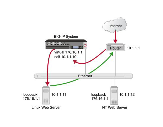
With the Layer 2 nPath routing configuration, you can route outgoing server traffic around the BIG-IP system directly to an outbound router. This method of traffic management increases outbound throughput because packets do not need to be transmitted to the BIG-IP system for translation and then forwarded to the next hop.
Note: The type of virtual server that processes the incoming traffic must be a transparent, non-translating type of virtual server.
In bypassing the BIG-IP system on the return path, Layer 2 nPath routing departs significantly from a typical load-balancing configuration. In a typical load-balancing configuration, the destination address of the incoming packet is translated from that of the virtual server to that of the server being load balanced to, which then becomes the source address of the returning packet. A default route set to the BIG-IP system then sees to it that packets returning to the originating client return through the BIG-IP system, which translates the source address back to that of the virtual server.
Note: Do not attempt to use nPath routing for Layer 7 traffic. Certain traffic features do not work properly if Layer 7 traffic bypasses the BIG-IP system on the return path.
The Layer 2 nPath routing configuration differs from the typical BIG-IP load balancing configuration in the following ways:
- The default route on the content servers must be set to the router’s internal address (10.1.1.1 in the illustration) rather than to the BIG-IP system’s floating self IP address (10.1.1.10). This causes the return packet to bypass the BIG-IP system.
- If you plan to use an nPath configuration for TCP traffic, you must create a Fast L4 profile with the following custom settings:
- Enable the Loose Close setting. When you enable this setting, the TCP protocol flow expires more quickly, after a TCP FIN packet is seen. (A FIN packet indicates the tearing down of a previous connection.)
- Set the TCP Close Timeout setting to the same value as the profile idle timeout if you expect half closes. If not, you can set this value to 5 seconds.
- Because address translation and port translation have been disabled, when the incoming packet arrives at the pool member it is load balanced to the virtual server address (176.16.1.1 in the illustration), not to the address of the server. For the server to respond to that address, that address must be configured on the loopback interface of the server and configured for use with the server software.
When you configure nPath for UDP traffic, the BIG-IP system tracks packets sent between the same source and destination address to the same destination port as a connection. This is necessary to ensure the client requests that are part of a session always go to the same server. Therefore, a UDP connection is really a form of persistence, because UDP is a connectionless protocol.
To calculate the timeout for UDP, estimate the maximum amount of time that a server transmits UDP packets before a packet is sent by the client. In some cases, the server might transmit hundreds of packets over several minutes before ending the session or waiting for a client response.
When you configure nPath for TCP traffic, the BIG-IP system recognizes only the client side of the connection. For example, in the TCP three-way handshake, the BIG-IP system sees the SYN from the client to the server, and does not see the SYN acknowledgment from the server to the client, but does see the acknowledgment of the acknowledgment from the client to the server. The timeout for the connection should match the combined TCP retransmission timeout (RTO) of the client and the node as closely as possible to ensure that all connections are successful.
The maximum initial RTO observed on most UNIX and Windows systems is approximately 25 seconds. Therefore, a timeout of 51 seconds should adequately cover the worst case. When a TCP session is established, an adaptive timeout is used. In most cases, this results in a faster timeout on the client and node. Only in the event that your clients are on slow, lossy networks would you ever require a higher TCP timeout for established connections.
You can create a custom Fast L4 profile to manage Layer 4 traffic more efficiently.
-
On the Main tab, click Local Traffic > Profiles > Protocol > Fast L4.
The Fast L4 screen opens.
-
Click Create.
The New Fast L4 profile screen opens.
-
In the Name field, type a unique name for the profile.
-
Select the Custom check box.
-
Select the Loose Close check box only for a one-arm virtual server configuration.
-
Set the TCP Close Timeout setting, according to the type of traffic that the virtual server will process.
-
Click Finished.
The custom Fast L4 profile appears in the list of Fast L4 profiles.
After you create a custom Fast L4 profile, you need to create a server pool.
-
On the Main tab, click Local Traffic > Pools.
The Pool List screen opens.
-
Click Create.
The New Pool screen opens.
-
In the Name field, type a unique name for the pool.
-
For the Health Monitors setting, in the Available list, select a monitor type, and click << to move the monitor to the Active list.
Tip: Hold the Shift or Ctrl key to select more than one monitor at a time.
-
Using the New Members setting, add each resource that you want to include in the pool:
-
(Optional) In the Node Name field, type a name for the node portion of the pool member.
-
In the Address field, type an IP address.
-
In the Service Port field, type a port number, or select a service name from the list.
-
(Optional) In the Priority field, type a priority number.
-
Click Add.
-
-
Click Finished.
After you create a server pool, you need to create a virtual server that references the profile and pool you created.
-
On the Main tab, click Local Traffic > Virtual Servers.
The Virtual Server List screen opens.
-
Click Create.
The New Virtual Server screen opens.
-
In the Name field, type a unique name for the virtual server.
-
For the Destination Address/Mask setting, confirm that the Host button is selected, and type the IP address in CIDR format.
The supported format is address/prefix, where the prefix length is in bits. For example, an IPv4 address/prefix is
10.0.0.1or10.0.0.0/24, and an IPv6 address/prefix isffe1::0020/64or2001:ed8:77b5:2:10:10:100:42/64. When you use an IPv4 address without specifying a prefix, the BIG-IP system automatically uses a/32prefix.Note: The IP address you type must be available and not in the loopback network.
-
From the Configuration list, select Advanced.
-
From the Type list, select Performance (Layer 4).
-
From the Protocol list, select one of the following:
- UDP
- TCP
- *All Protocols
-
From the Protocol Profile (Client) list, select a predefined or user-defined Fast L4 profile.
-
For the Address Translation setting, clear the Enabled check box.
-
For the Port Translation setting, clear the Enabled check box.
-
In the Resources area of the screen, from the Default Pool list, select the relevant pool name.
-
Click Finished.
You must place the IP address of the virtual server (176.16.1.1 in the illustration) on the loopback interface of each server. Most UNIX variants have a loopback interface named lo0. Consult your server operating system documentation for information about configuring an IP address on the loopback interface. The loopback interface is ideal for the nPath configuration because it does not participate in the ARP protocol.
For inbound traffic, you must define a route through the BIG-IP system self IP address to the virtual server. In the example, this route is 176.16.1.1, with the external self IP address 10.1.1.10 as the gateway.
Note: You need to set this route only if the virtual server is on a different subnet than the router.
For information about how to define this route, please refer to the documentation provided with your router.