Updated Date: 07/07/2026
Configuring IPsec Using Manually Keyed Security Associations
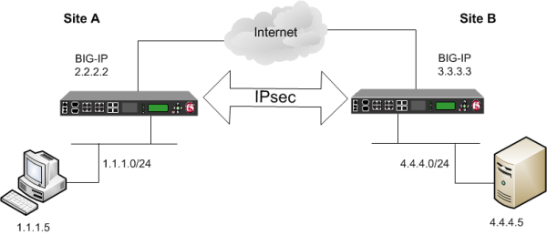
You can configure an IPsec tunnel when you want to use a protocol other than SSL to secure traffic that traverses a wide area network (WAN), from one BIG-IP ®system to another. Typically, you would use the Internet Key Exchange (IKE) protocol to negotiate the secure channel between the two systems. If you choose not to use IKE, you must create manual security associations for IPsec security. A manual security association statically defines the specific attribute values that IPsec should use for the authentication and encryption of data flowing through the tunnel.
The implementation of the IPsec protocol suite using manually keyed security associations consists of these components:
- IPsec policy
- An IPsec policy is a set of information that defines the specific IPsec protocol to use (ESP or AH), and the mode (Transport, Tunnel, or iSession®). For Tunnel mode, the policy also specifies the endpoints for the tunnel. The way that you configure the IPsec policy determines the way that the BIG-IP system manipulates the IP headers in the packets.
- Manual security association
- A manual security association is set of information that the IPsec protocol uses to authenticate and encrypt application traffic.
Note: When you manually create a security association instead of using IKE, the peer systems do not negotiate these attributes. Peers can communicate only when they share the same configured attributes.
- Traffic selector
- A traffic selector is a packet filter that defines what traffic should be handled by a IPsec policy. You define the traffic by source and destination IP addresses and port numbers.
Tunnel mode causes the IPsec protocol to encrypt the entire packet (the payload plus the IP header). This encrypted packet is then included as the payload in another outer packet with a new header. Traffic sent in this mode is more secure than traffic sent in Transport mode, because the original IP header is encrypted along with the original payload.
You can configure an IPsec tunnel to secure traffic that traverses a wide area network (WAN), such as from one BIG-IP® system to another.
Before you begin configuring IPsec, verify that these modules, system objects, and connectivity exist on the BIG-IP systems in both the local and remote locations:
- BIG-IP Local Traffic Manager
- This module directs traffic securely and efficiently to the appropriate destination on a network.
- Self IP address
- Each BIG-IP system must have at least one self IP address, to be used in specifying the ends of the IPsec tunnel.
- The default VLANs
- These VLANs are named
externalandinternal. - BIG-IP system connectivity
- Verify the connectivity between the client or server and its BIG-IP device, and between each BIG-IP device and its gateway. For example, you can use
pingto test this connectivity.
For IPsec, you create a forwarding (IP) type of virtual server to intercept IP traffic and direct it over the tunnel. With a forwarding (IP) virtual server, destination address translation and port translation are disabled.
-
On the Main tab, click Local Traffic > Virtual Servers.
The Virtual Server List screen opens.
-
Click Create.
The New Virtual Server screen opens.
-
In the Name field, type a unique name for the virtual server.
-
From the Type list, select Forwarding (IP).
-
In the Destination Address/Mask field, type a wildcard network address in CIDR format, such as
0.0.0.0/0for IPv4 or::/0for IPv6, to accept any traffic. -
From the Service Port list, select *All Ports.
-
From the Protocol list, select *All Protocols.
-
From the VLAN and Tunnel Traffic list, retain the default selection, All VLANs and Tunnels.
-
Click Finished.
When you are using manual security associations for an IPsec tunnel between two BIG-IP systems, you must create two custom IPsec policies on each system, one to use for outbound traffic and the other for inbound traffic. You establish the directionality of a policy by associating it with a unidirectional traffic selector.
-
On the Main tab, click Network > IPsec > IPsec Policies.
-
Click the Create button.
The New Policy screen opens.
-
In the Name field, type a unique name for the policy.
-
For the IPsec Protocol setting, retain the default selection, ESP.
-
From the Mode list, select Tunnel.
The screen refreshes to show additional related settings.
-
In the Tunnel Local Address field, type the IP address of the BIG-IP system that initiates the traffic.
To specify a route domain ID in an IP address, use the format n.n.n.n%ID.
Note: When you use IKEv1, the BIG-IP system supports a maximum of 512 route domains.
For the outbound policy, this is the IP address of the local BIG-IP system. For the inbound policy, this is the IP address of the remote BIG-IP system.
This table shows sample outbound and inbound tunnel local addresses configured on BIG-IP A and BIG-IP B.
System Name Traffic Direction Tunnel Local Address BIG-IP A Outbound 2.2.2.2Inbound 3.3.3.3BIG-IP B Outbound 3.3.3.3Inbound 2.2.2.2 -
In the Tunnel Remote Address field, type the IP address of the BIG-IP system that receives the traffic.
To specify a route domain ID in an IP address, use the format n.n.n.n%ID.
Note: When you use IKEv1, the BIG-IP system supports a maximum of 512 route domains.
For the outbound policy, this is the IP address of the remote BIG-IP system. For the inbound policy, this is the IP address of the local BIG-IP system.
This table shows sample outbound and inbound tunnel remote addresses configured on BIG-IP A and BIG-IP B.
System Name Traffic Direction Tunnel Remote Address BIG-IP A Outbound 3.3.3.3Inbound 2.2.2.2BIG-IP B Outbound 2.2.2.2Inbound 3.3.3.3 -
For the Authentication Algorithm setting, retain the default value, or select the algorithm appropriate for your deployment.
-
For the Encryption Algorithm setting, retain the default value, or select the algorithm appropriate for your deployment.
-
For the Perfect Forward Secrecy setting, select the option appropriate for your deployment.
-
For the IPComp setting, specify whether to use IPComp encapsulation, which performs packet-level compression before encryption:
- Retain the default value None, if you do not want to enable packet-level compression before encryption.
- Select DEFLATE to enable packet-level compression before encryption.
-
For the Lifetime setting, retain the default value, 1440.
This is the length of time (in minutes) before the current security association expires.
-
Click Finished.
The screen refreshes and displays the new IPsec policy in the list.
-
Repeat this task for outbound and inbound traffic policies on both the local and remote BIG-IP systems.
When you are finished, you should have created four separate IPsec policies, two on each system.
Before you start this task, you need to create two custom IPsec policies on the BIG-IP system, one for outbound traffic and another for inbound traffic.
You can manually create security associations to specify the security attributes for a given IPsec communication session. For the manual configuration, you need to create two manual security associations for each connection, one for outbound traffic and the other for inbound traffic.
Important: You must perform this task on both BIG-IP systems.
-
On the Main tab, click Network > IPsec > Manual Security Associations.
-
Click the Create button.
The New Security Association screen opens.
-
In the Name field, type a unique name for the security association.
-
In the Description field, type a brief description of the security setting.
-
In the SPI field, type a unique number for the security parameter index.
This number must be an integer between 256 and 4294967296.
-
In the Source Address field, type the source IP address.
This IP address must match the IP address specified for the Tunnel Local Address in the selected IPsec policy.
-
In the Destination Address field, type the IP address in CIDR format.
The supported format is address/prefix, where the prefix length is in bits. For example, an IPv4 address/prefix is
10.0.0.1or10.0.0.0/24, and an IPv6 address/prefix isffe1::0020/64or2001:ed8:77b5:2:10:10:100:42/64. When you use an IPv4 address without specifying a prefix, the BIG-IP system automatically uses a/32prefix.This IP address must match the IP address specified for the Tunnel Remote Address in the selected IPsec policy.
-
In the Authentication Key field, type a key value.
This value can by any double-quoted character string up to a maximum of 128 characters
-
From the Encryption Algorithm list, select the algorithm appropriate to your deployment.
-
In the Encryption Key field, type a key value.
This value can by any double-quoted character string up to a maximum of 128 characters
-
From the IPsec Policy Name list, select an IPsec policy.
- For the outbound security association, select the IPsec policy you created for outbound traffic.
- For the inbound security association, select the IPsec policy you created for inbound traffic.
-
Repeat this task for security associations that handle outbound and inbound traffic on both the local and remote BIG-IP systems.
When you are finished, you should have manually created four separate security associations, two on each system.
Before you start this task, you need to create two custom IPsec policies on the BIG-IP system, one for outbound traffic and another for inbound traffic.
You can use this procedure to create IPsec traffic selectors that reference custom IPsec policies for unidirectional traffic in an IPsec tunnel for which you have manually keyed security associations. You need to create two traffic selectors on each BIG-IP system, one for outbound traffic and the other for inbound traffic. Each traffic selector you create filters traffic based on the IP addresses and port numbers that you specify, as well as the custom IPsec policy you assign.
Important: You must perform this task on both BIG-IP systems.
-
On the Main tab, click Network > IPsec > Traffic Selectors.
-
Click Create.
The New Traffic Selector screen opens.
-
In the Name field, type a unique name for the traffic selector.
-
In the Description field, type a brief description of the traffic selector.
-
From the Configuration list, select Advanced.
-
For the Source IP Address or CIDR setting, type an IP address.
This IP address must match the IP address specified for the Tunnel Local Address in the selected IPsec policy.
-
From the Source Port list, select the source port for which you want to filter traffic, or retain the default value *All Ports.
-
For the Destination IP Address or CIDR setting, type an IP address.
This IP address must match the IP address specified for the Tunnel Remote Address in the selected IPsec policy.
-
From the Destination Port list, select the destination port for which you want to filter traffic, or retain the default value * All Ports.
-
From the Protocol list, select the protocol for which you want to filter traffic.
You can select * All Protocols, TCP, UDP, ICMP, or Other. If you select Other, you must type a protocol name.
-
From the Direction list, select Out or In, depending on whether this traffic selector is for outbound or inbound traffic.
-
From the IPsec Policy Name list, select an IPsec policy.
- For the outbound traffic selector, select the IPsec policy you created for outbound traffic.
- For the inbound traffic selector, select the IPsec policy you created for inbound traffic.
-
Click Finished.
The screen refreshes and displays the new IPsec traffic selector in the list.
-
Repeat this task for traffic selectors that handle outbound and inbound traffic on both the local and remote BIG-IP systems.
When you are finished, you should have manually created four separate traffic selectors, two on each system.
After you have configured an IPsec tunnel and before you configure additional functionality, you can verify that the tunnel is passing traffic.
Note: Only data traffic matching the traffic selector triggers the establishment of the tunnel.
-
Access the
tmshcommand-line utility. -
Before sending traffic, type this command at the prompt.
tmsh modify net ipsec ike-daemon ikedaemon log-level debugThis command increases the logging level to display the messages that you want to view.
-
Send data traffic to the destination IP address specified in the traffic selector.
-
For an IKEv1 configuration, check the IKE Phase 1 negotiation status by typing this command at the prompt.
racoonctl -l show-sa isakmpThis example shows a result of the command.
Destinationis the tunnel remote IP address.Destination Cookies ST S V E Created Phase2 165.160.15.20.500 98993e6 . . . 22c87f1 9 I 10 M 2012-06-27 16:51:19 1This table shows the legend for interpreting the result.
Column Displayed Description ST (Tunnel Status) 1 Start Phase 1 negotiation 2 msg 1 received 3 msg 1 sent 4 msg 2 received 5 msg 2 sent 6 msg 3 received 7 msg 3 sent 8 msg 4 received 9 isakmp tunnel established 10 isakmp tunnel expired S I Initiator R Responder V (Version Number) 10 ISAKMP version 1.0 E (Exchange Mode) M Main (Identity Protection) A Aggressive Phase2 <n> Number of Phase 2 tunnels negotiated with this IKE peer -
For an IKEv2 configuration, check the IKE Phase 2 negotiation status by typing this command at the prompt.
racoonctl -ll show-sa internalThis example shows a result of this command.
Sourceis the tunnel local IP address.Destinationis the tunnel remote IP address.Source Destination Status Side 10.100.20.3 165.160.15.20 sa established [R]This table shows the legend for interpreting the result.
Column Displayed Side I (Initiator) R (Responder) Status init start acquire getspi sent getspi done 1st msg sent 1st msg recvd commit bit sa added sa established sa expired -
To verify the establishment of dynamic negotiated Security Associations (SAs), type this command at the prompt.
tmsh show net ipsec ipsec-saFor each tunnel, the output displays IP addresses for two IPsec SAs, one for each direction, as shown in the example.
IPsec::SecurityAssociations 10.100.20.3 -> 165.160.15.20 SPI(0x7b438626) in esp (tmm: 6) 165.160.15.20 -> 10.100.20.3 SPI(0x5e52a1db) out esp (tmm: 5) -
To display the details of the dynamic negotiated Security Associations (SAs), type this command at the prompt.
tmsh show net ipsec ipsec-sa all-propertiesFor each tunnel, the output displays the details for the IPsec SAs, as shown in the example.
IPsec::SecurityAssociations 165.160.15.20 -> 10.100.20.3 ----------------------------------------------------------------------------- tmm: 2 Direction: out; SPI: 0x6be3ff01(1810104065); ReqID: 0x9b0a(39690) Protocol: esp; Mode: tunnel; State: mature Authenticated Encryption : aes-gmac128 Current Usage: 307488 bytes Hard lifetime: 94 seconds; unlimited bytes Soft lifetime: 34 seconds; unlimited bytes Replay window size: 64 Last use: 12/13/2012:10:42 Create: 12/13/2012:10:39 -
To display the details of the IKE-negotiated SAs (IKEv2), type this command at the prompt.
tmsh show net ipsec ike-sa all-properties -
To filter the Security Associations (SAs) by traffic selector, type this command at the prompt.
tmsh show net ipsec ipsec-sa traffic-selector ts_codecYou can also filter by other parameters, such as SPI (
spi), source address (src_addr), or destination address (dst_addr)The output displays the IPsec SAs that area associated with the traffic selector specified, as shown in the example.
IPsec::SecurityAssociations 10.100.115.12 -> 10.100.15.132 SPI(0x2211c0a9) in esp (tmm: 0) 10.100.15.132 -> 10.100.115.12 SPI(0x932e0c44) out esp (tmm: 2) -
Check the IPsec stats by typing this command at the prompt.
tmsh show net ipsec-statIf traffic is passing through the IPsec tunnel, the stats will increment.
------------------------------------------------------------------- Net::Ipsec Cmd Id Mode Packets In Bytes In Packets Out Bytes Out ------------------------------------------------------------------- 0 TRANSPORT 0 0 0 0 0 TRANSPORT 0 0 0 0 0 TUNNEL 0 0 0 0 0 TUNNEL 0 0 0 0 1 TUNNEL 353.9K 252.4M 24.9K 1.8M 2 TUNNEL 117.9K 41.0M 163.3K 12.4M -
If the SAs are established, but traffic is not passing, type one of these commands at the prompt.
tmsh delete net ipsec ipsec-sa(IKEv1)tmsh delete net ipsec ike-sa(IKEv2)This action deletes the IPsec tunnels. Sending new traffic triggers SA negotiation and establishment.
-
If traffic is still not passing, type this command at the prompt.
racoonctl flush-sa isakmpThis action brings down the control channel. Sending new traffic triggers SA negotiation and establishment.
-
View the
/var/log/racoon.logto verify that the IPsec tunnel is up.These lines are examples of the messages you are looking for.
2012-06-29 16:45:13: INFO: ISAKMP-SA established 10.100.20.3[500]-165.160.15.20[500] spi:3840191bd045fa51:673828cf6adc5c61 2012-06-29 16:45:14: INFO: initiate new phase 2 negotiation: 10.100.20.3[500]<=>165.160.15.20[500] 2012-06-29 16:45:14: INFO: IPsec-SA established: ESP/Tunnel 165.160.15.20[0]->10.100.20.3[0] spi=2403416622(0x8f413a2e) 2012-06-29 16:45:14: INFO: IPsec-SA established: ESP/Tunnel 10.100.20.3[0]->165.160.15.20[0] spi=4573766(0x45ca46 -
To turn on IKEv2 logging on a production build, complete these steps.
Important: If you are using IKEv2, you can skip these steps; the BIG-IP system enables IPsec logging by default.
-
Configure the log publisher for IPsec to use.
% tmsh create sys log-config publisher ipsec { destinations add { local-syslog }} % tmsh list sys log-config publisher ipsec sys log-config publisher ipsec { destinations { local-syslog { } } } -
Attach the log publisher to the
ike-daemonobject.tmsh modify net ipsec ike-daemon ikedaemon log-publisher ipsec
-
-
For protocol-level troubleshooting, you can increase the debug level by typing this command at the prompt.
tmsh modify net ipsec ike-daemon ikedaemon log-level debug2Important: Use this command only for debugging. It creates a large log file, and can slow the tunnel negotiation.
Note: Using this command flushes existing SAs.
-
After you view the results, return the debug level to normal to avoid excessive logging by typing this command at the prompt.
tmsh modify net ipsec ike-daemon ikedaemon log-level infoNote: Using this command flushes existing SAs.