Updated Date: 07/07/2026
Using BIG-IQ to create and deploy SSL Orchestrator configurations
BIG-IQ SSL Orchestrator Guided Configuration guides you through setting up a particular use case on the SSL Orchestrator (SSLO) system. This tool provides you with a collection of templates that you configure to suit your requirements. These templates require minimal input and are liberally sprinkled with tool tips that explain the details you need to supply.
Before you begin the guided configuration, you must:
- Discover and import SSLO devices.
- Confirm or configure the SSLO RPM version.
When you start the guided configuration, the wizard steps you through the process of creating and configuring your SSLO solution. You start by configuring the topology and then assemble the SSL objects you want to use. As you step through the wizard, you build a Service Chain that defines the sequence of SSL objects you want to use. Here is the sequence of tasks for creating an SSLO configuration:
- Select and configure a topology for your SSLO solution.
- Configure the SSL settings for your solution.
- Create or edit the SSL services that you want to include in your service chain.
- Build your service chain
- Add or update security policies.
- Add or update interception rules.
- Add or update egress settings.
- Add or update log settings.
- Deploy the SSLO configuration.
You can omit any of these object types as you go, and then come back and add, revise, or delete them as necessary.
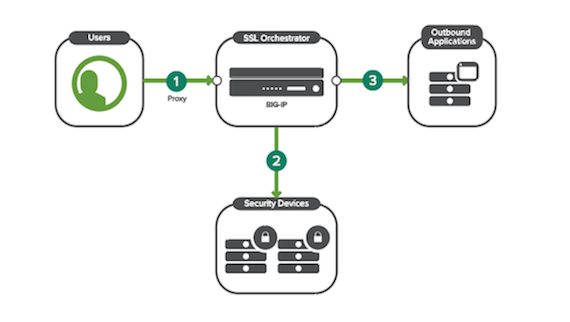
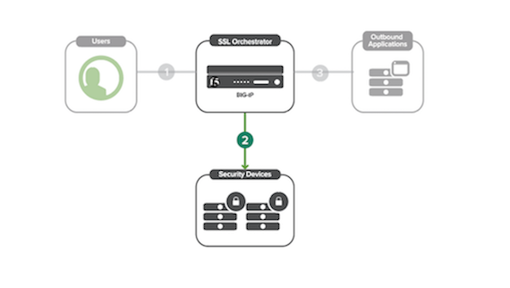
Layer 3 outbound transparent proxy topologies provide internal users with access to external remote resources when the organization does not own the application resources and SSL keys. Within L3 topology deployments, traffic is routed to the BIG-IP device.
- The internal traffic takes a routed path into and out of the BIG-IP device. The client is unaware of the SSL Orchestrator device while en-route to the server.
- The BIG-IP device traffic decrypts the traffic and sends it to the security devices.
- The BIG-IP then re-encrypts the traffic and the traffic is then routed out to the applications and the internet.
Depending on which type of protocol you select for your L3 outbound transparent topology, the system will guide you through different pages to configure corresponding required objects, as shown in the table. Be prepared, and have this information on-hand before beginning a topology configuration.
When you create or edit an L3 outbound transparent topology service, the system guides you through a sequence of pages that you use to configure the required objects. The sequence of screens depends on the protocol type you select. This table lists the objects needed for each supported protocol. Be prepared, and have this information on-hand before you start configuring the L3 outbound transparent topology.
| Protocol | Objects to configure in an L3 outbound transparent topology workflow |
|---|---|
| TCP | SSL Configuration→ Service → Service Chain → Security Policy → Interception Rule → Egress Setting Log → Log Settings (SSLO RPM 6.0 and later) |
| UDP | Service → Service Chain → Security Policy → Interception Rule → Egress Setting → Log Settings (SSLO RPM 6.0 and later) |
| Other | Interception Rule → Egress Setting → Settings (SSLO RPM 6.0 and later) |
| Any | SSL Configuration → Service → Service Chain → Security Policy → Interception Rule → Egress Setting → Log Settings (SSLO RPM 6.0 and later) |
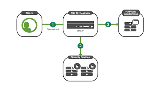
Layer 3 outbound topologies provide internal users with access to external remote resources when the organization does not own the application resources and SSL keys. Within L3 topology deployments, traffic is routed to the BIG-IP device.
- The internal routed traffic is targeted to an explicit proxy by means of the BIG-IP device after an explicit proxy request.
- The BIG-IP device decrypts the traffic and sends it to the security devices.
- The BIG-IP device then re-encrypts the traffic and the traffic is then routed out to the applications and the internet.
Depending on which type of protocol you select for your L3 outbound explicit topology, the system guides you through different pages to configure corresponding required objects, as shown in the table. Be prepared with this information on-hand before you begin a topology configuration.
| Protocol | Objects to configure for an L3 outbound explicit proxy topology workflow |
|---|---|
| TCP | SSL Configuration → Service → Service Chain → Security Policy → Interception Rule → Egress Setting → Log Settings (SSLO RPM 6.0 and later) |
| UDP | Disable L3 outbound explicit proxy when using UDP protocol |
| Other | Disable L3 outbound explicit proxy when using UDP protocol |
| Any | SSL Configuration → Service → Service Chain → Security Policy → Interception Rule → Egress Setting → Log Settings (SSLO RPM 6.0 and later) |
To configure an L2 outbound topology, you must set up an L2 wired device on the managed BIG-IP device. Within an L2 topology deployment, traffic is routed through the BIG-IP device, and exposes no external IP addresses, because it is effectively transparent on the wire.
- Traffic flows into the BIG-IP device.
- The BIG-IP device decrypts the traffic and sends it to Security Devices.
- The BIG-IP device re-encrypts the traffic and sends it out to the applications.
Depending on which protocol you select for your L2 outbound topology, the system guides you through different screens to configure corresponding required objects, as shown in the table. Be prepared, and have this information on-hand before you begin a topology configuration.
| Protocol | Objects to configure in an L2 outbound topology workflow |
|---|---|
| TCP | SSL Configuration → Service → Service Chain → Security Policy → Interception Rule → Log Settings (SSLO RPM 6.0 and later) |
| UDP | Service → Service Chain → Security Policy → Interception Rule → Log Settings (SSLO RPM 6.0 and later) |
| Other | Interception Rule |
| Any | SSL Configuration → Service → Service Chain → Security Policy → Interception Rule → Log Settings (SSLO RPM 6.0 and later) |
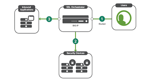
Layer 3 inbound topologies provide internal users with access to inbound applications. Within L3 topology deployments, traffic is routed to the BIG-IP device.
- Traffic flows into the BIG-IP device.
- The BIG-IP device decrypts the traffic and sends it to the security devices.
- The BIG-IP device re-encrypts the traffic and sends it out to the applications.
Depending on which protocol you select for your L3 inbound topology, the system guides you through different screens to configure corresponding required objects, as shown in the table. Be prepared, and have this information on-hand before beginning a topology configuration.
| Protocol | Objects to configure for an L3 inbound topology workflow |
|---|---|
| TCP | SSL Configuration → Service → Service Chain → Security Policy → Interception Rule → Egress Setting → Log Settings (SSLO RPM 6.0 and later) |
| UDP | Service → Service Chain → Security Policy → Interception Rule → Egress Setting → Log Settings (SSLO RPM 6.0 and later) |
| Other | Interception Rule → Egress Setting → Log Settings (SSLO RPM 6.0 and later) |
| Any | Disable L3 Inbound option in SSL Orchestrator Topologies |
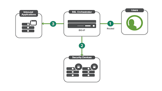
To configure an L2 inbound topology, you must set up an L2 wired device on the managed BIG-IP device. Within an L2 topology deployment, the traffic flows through the BIG-IP device and exposes no external IP addresses; it is effectively transparent on the wire.
- Traffic flows into the BIG-IP device.
- The BIG-IP device decrypts the traffic and sends it to the security devices.
- The BIG-IP device re-encrypts the traffic and sends it out to the applications.
Depending on which protocol you select for your L2 inbound topology, the system will guide you through different pages to configure corresponding required objects, as shown in the table. Be prepared, and have this information on-hand before beginning a topology configuration.
| Protocol | Objects to configure for an L2 inbound topology |
|---|---|
| TCP | SSL → Service → Service Chain → Security Policy → Interception Rule → Log Settings (SSLO RPM 6.0 and later) |
| UDP | Service → Service Chain → Security Policy → Interception Rule → Log Settings (SSLO RPM 6.0 and later) |
| Other | Interception Rule → Log Settings (SSLO RPM 6.0 and later) |
| Any | Disable L2 Inbound option in SSL Orchestrator Topologies |
To configure an existing application topology, you must have an SSL add-on license, available within the managed BIG-IP device. In the workflow for existing applications configurations, there is no option to select a network protocol.
- Traffic flows into the BIG-IP device. (To be configured out of this topology.)
- The BIG-IP device decrypts traffic and sends it to the security devices.
- The BIG-IP device re-encrypts traffic and sends it out to the applications. (To be configured out of this flow.)
For existing application topologies, there is no option to select a protocol. The system guides you through different screens to configure corresponding required objects, as shown here. Be prepared, and have this information on-hand before beginning a topology configuration.
- Existing application topology workflow
- Service → Service Chain → Security Policy
Sometimes, you might want to configure SSL configurations, services, service chains, security policies outside of an SSL Orchestrator (SSLO) topology, so you can have one object associated with multiple topologies. In this scenario, you might want to configure SSLO objects independently and then mass deploy them to multiple configurations. Once an object is updated outside of a topology in this way, you must redeploy all topologies to implement desired changes on the managed BIG-IP devices.
To independently deploy an SSL configuration to an existing SSLO configuration, make sure that you have deployed an SSLO topology in BIG-IQ using the guided configuration. To do so, navigate to the Configuration tab, and select SSL Orchestrator. From there, you may select any of the following menus to edit an object independently: SSL Configuration, Service, Service Chain, or Security Policy.
To add one of these objects to a topology, navigate to the corresponding object within a topology workflow. At the top of the page, there will be two options for configuring your object: Create New or Use Existing. Select Use Existing to use a previously-configured object within this SSLO configuration.
To edit a deployed topology, you must first select one of the six topology types and configure and deploy it. You cannot change the topology type once you have deployed the configuration. You can not edit fields that are unavailable once they are deployed. You can however edit the individual object’s options on the left.
You make changes to an existing topology to edit the individual objects on a single instance of a deployed configuration.
-
In the Configuration tab, click SSL ORCHESTRATOR > Topologies
-
Within the UI, edit the target object using the pencil icon.
-
Select Save&Next.
-
Select Deploy to push your changes to a deployed topology.
Editing objects within a deployed topology alters these objects solely within the BIG-IP devices associated with that deployed topology. Once you have deployed these changes, allow up to fifteen minutes for these changes to appear in your managed BIG-IP device.
You can create independent objects for future deployment to an SSL Orchestrator topology within BIG-IQ. To do so, enter the Configuration tab and select SSL Orchestrator. From there, you can independently create SSL Configurations, Services, Service Chains, and Security Policies for future deployment from the left-hand menu. Once an object is created outside of a topology in this way, you must add this object to an existing topology and redeploy it to the managed BIG-IP devices to implement the new object.
Before you begin, you will need to have BIG-IP devices with the SSLO service discovered and imported. You will also need to ensure that all devices you wish to add to the Office 365 fetch schedule are running the same SSLO RPM version. If you need to upgrade the SSLO version on a device or discover and import SSLO, please follow the procedures in Managing SSL Orchestrator Using BIG-IQ.
Office 365 URLs are a set of URLs that Microsoft has defined for Office365 resources. From BIG-IQ, you can create a schedule to fetch Office 365 URLs and configure URL categories, which you then attach to an SSLO security policy and deploy in an SSLO topology configuration. The categories that will be created from this fetch are Allow, Default, Optimize and All (All includes URLs from all categories). If you add the Allow category of O365 URLs to a security policy, the traffic will not be inspected. If you add the Default category to a policy, the package will be inspected. If you select the Optimize category to add to a security policy, you are choosing to optimize traffic speed for critical Microsoft endpoints such as Outlook and Sharepoint. If you fetch All categories, you can add all of the above Microsoft endpoints to a security policy.
This list is dynamic and is frequently updated by Microsoft. You can also use this page to view the result of the last run and to view the past and upcoming run schedule.
-
Scheduler Properties
-
Navigate to Configuration > SSL Orchestrator > O365 URLs.
-
For Frequency, specify how often you would like to fetch O365 URL categories. From the dropdown menu, select a cadence of Monthly or Weekly and enter a number between 1 and 28 for the day of the month you want to run the report. Finally, specify the time in a 24-hour format. Enter in the format
HR: MIN. -
For Start Date/Time, enter a date or use the calendar widget to pick a date in the future to begin running the report. Specify a time in a 24-hour format.
-
To authorize BIG-IQ to immediately fetch O365 URL categories, select the checkbox by Fetch Now.
-
O365 URL Category Configuration
-
Specify an Endpoint from the dropdown menu from which to fetch the URL categories.
-
For Use required URLs only, select Yes to fetch the minimum required URLs for O365 connectivity. Select No to fetch all URLs, including the minimum required ones.
-
For Include URLs, enter any URLs that are not categorized as O365 URLs that you would like to fetch. Add additional URLs with the + icon.
-
To exclude URLs or domain extensions from this fetch, enter the URL or extension in the Exclude URLs.
For example, if you want to exclude google.com from your fetch and all addresses ending in .net, enter
google.comin the field, select the + icon to add an additional line. On the next line, enter.net. -
To choose managed BIG-IP devices or device clusters on which to deploy the URL categories, use the arrows to move the BIG-IP devices or clusters from the Available to the Selected menu.
Note: All selected BIG-IP devices must be running the same SSLO RPM version.
-
Service Area
-
If you would like to fetch URLs for a specific category such as Microsoft Exchange, select Yes. To exclude a category from the scheduled fetch, select No next to that category.
Note: BIG-IQ will always fetch the common O365 URLs.
-
Run Information
-
Under the Run Information section, you can view the the result of the last run, as well as the devices and clusters that the URL categories were deployed to. You can also view the last run time, and the next scheduled run time.
-
Select Save to save this schedule.
After you have finished configuration, you can add the Office 365 URL categories to a security policy rule when the network traffic matches all categories. You can then deploy the security policy on target BIG-IP devices.
To make sure that your SSL Orchestrator configurations are consistent between your BIG-IP devices and BIG-IQ Centralized Management, it is important to follow a set of best-practices to retain optimal and congruent device configurations. These best-practices include:
- Make configuration changes to your SSLO topologies only on the BIG-IQ. Making configuration changes on both the BIG-IP device and the BIG-IQ can cause unexpected results.
- Create unique names for each SSL Orchestrator topology.
- Allow at least 15 minutes for SSLO configuration changes you make on the BIG-IQ to show up in the BIG-IP device user interface.
BIG-IQ 7.0.0 supports deploying new BIG-IP devices provisioned for SSL Orchestrator directly from BIG-IQ.