Updated Date: 06/30/2026
F5 rSeries system initial configuration
The Setup wizard is available to assist you in setting up basic management networking on the rSeries system. You can choose to enable DHCP and have your IP address settings configured automatically, or disable DHCP and manually configure your IP address settings.
After you have configured network settings using the Setup wizard, you can use the rSeries webUI to perform additional configuration of your system, including:
- Running the Setup wizard
- Logging in to the webUI
- Licensing the system
- Creating required VLANs
- Importing a tenant image
- Deploying a tenant
After the platform is physically installed and powered on in your data center, you can access the command line interface (CLI) of the system and run the Setup wizard to perform basic configuration. In this scenario, you run the Setup wizard and enable DHCP. The wizard steps you through configuration of DHCP, DNS, and NTP on the system. With DHCP enabled, management IP addresses are assigned automatically, so you do not need to configure them.
Important: Upon completion, the Setup wizard automatically puts the system into appliance mode, which disables the root account and bash access.
-
Connect to the system using a management console or console server.
Note: The default baud rate and serial port configuration is 19200/8-N-1.
-
Log in to the command line interface (CLI) of the system using an account with admin access.
Important: The default login credentials are admin/admin. When logging in as admin for the first time, the system prompts you to change the password. This also changes the default password for the root account to match that of the admin account.
When you log in to the system, you are in user (operational) mode.
-
After you change the admin password, log out as the admin user.
exitNote: You run the Setup wizard using the root account, but will need the admin user credentials to commit the configuration changes that you make using the Setup wizard.
The prompt changes back to the
loginprompt. -
Log in as the root user using the same password that you selected for the admin user.
Note: When logging in as root for the first time, the system prompts you to change the password.
The system has completed the boot sequence when this prompt displays:
`[root@appliance-1 ~]#`
-
Run the Setup wizard.
appliance-setup-wizardNote: The interactive Setup wizard displays. As you enter IP addresses during the setup process, the wizard populates those values in the appropriate fields on the screen.
___APPLIANCE_SETUP_WIZARD___ DHCP: true IPv4: [DHCP] prefix: [DHCP] system: [DHCP] gateway: [DHCP] IPv6: [DHCP] prefix: [DHCP] system: [DHCP] gateway: [DHCP] DNS: false server: [DNS] port: [DNS] NTP: false server: [NTP] port: [NTP] Would you like to configure a DNS server? Y/y: Yes N/n: No B/b: Back Q/q: Quit Enter: Submit -
When prompted whether you want to enable DHCP, enter
nand press Enter.If you do want to enable DHCP, enter
y, press Enter and then skip to step 10. -
When you are prompted to configure IPv4 management networking, enter
yand press Enter.-
Type the floating management IPv4 address for the system controllers and press Enter.
-
Type the management IPv4 address for controller-1 and press Enter.
-
Type the management IPv4 address for controller-2 and press Enter.
-
Type the IPv4 gateway address and press Enter.
-
Type the IPv4 prefix length (0-32) and press Enter.
-
-
Optionally, you can configure IPv6 management networking. If you choose to do this, when prompted to configure IPv6 management networking, enter
yand press Enter. Otherwise, entern, press Enter and then skip to step 10.-
Type the floating management IPv6 address for the system controllers and press Enter.
-
Type the management IPv6 address for controller-1 and press Enter.
-
Type the management IPv6 address for controller-2 and press Enter.
-
Type the IPv6 gateway address and press Enter.
-
Type the IPv6 prefix length (0-32) and press Enter.
-
-
When you are prompted to configure a DNS server, enter
yand press Enter.-
Type the IPv4 address for your DNS server and press Enter.
-
Type the port number for your DNS server and press Enter.
The default value is 53. To use the default, press Enter at the prompt, and the system will use the default value automatically.
-
-
When you are prompted to configure an NTP server, enter
yand press Enter.-
Type the IP address for your NTP server and press Enter.
-
Type the port number for your NTP server and press Enter.
The default value is 123. To use the default, press Enter at the prompt, and the system will use the default value automatically.
-
-
When you are prompted to commit the configuration, enter
yand press Enter. -
When you are prompted for a login username, enter your admin username and press Enter.
-
When you are prompted for a login password, enter your admin password and press Enter.
When the configuration commits successfully, these messages display in sequence:
DHCP...Committed NTP server IPv4 address...Committed Enabling appliance mode...Committed Configuration committed. Appliance mode enabled. Press Enter to exit. -
Verify that all networking settings are configured correctly.
-
Log in using the admin account.
su admin -
Verify that DHCP is enabled.
In this example, DHCP is confirmed as being enabled:
appliance-1# show running-config system mgmt-ip config dhcp-enabled system mgmt-ip config dhcp-enabled true -
Verify that the management port IP addresses are configured.
In this example, IPv4 addresses are confirmed as being configured:
appliance-1# show system mgmt-ip system mgmt-ip state ipv4 system address 192.0.2.10 system mgmt-ip state ipv4 prefix-length 24 system mgmt-ip state ipv4 gateway 192.0.2.254 system mgmt-ip state ipv6 system address :: system mgmt-ip state ipv6 prefix-length 0 system mgmt-ip state ipv6 gateway :: -
Verify that a DNS server is configured.
In this example, two DNS servers are confirmed as being configured:
appliance-1# show system dns ADDRESS ADDRESS PORT ----------------------------- 192.0.2.100 - 53 192.0.2.101 - 53 -
Verify that an NTP server is configured.
In this example, an NTP server is confirmed as being configured:
appliance-1# show system ntp
system ntp state enabled
ASSOCIATION                           ROOT   ROOT                POLL
ADDRESS       ADDRESS       PORT  VERSION  TYPE         IBURST  PREFER  STRATUM  DELAY  DISPERSION  OFFSET  INTERVAL
----------------------------------------------------------------------------------------------------------------------
pool.ntp.org  pool.ntp.org  123   4        POOL         false   true    -        -      -           -       -
-
The system is now set up. The Setup wizard automatically puts the system into appliance mode, which disables the root account and bash access. You can disable appliance mode from the CLI or webUI by using an admin account. For more information, see F5 rSeries Systems: Administration and Configuration at techdocs.f5.com. Next, you will continue configuring the system by accessing the webUI using the management IP address and applying a license.
Next, you will continue configuring the system by accessing the webUI using the floating management IP address and applying a license.
Before you can log in to the system, you must have completed initial configuration using the Setup wizard from a management console or console server. In this task, you use the management IP address that you specified during initial configuration.
You can now begin to administer the rSeries system by logging in to the webUI. Here you can adjust settings and view system status.
-
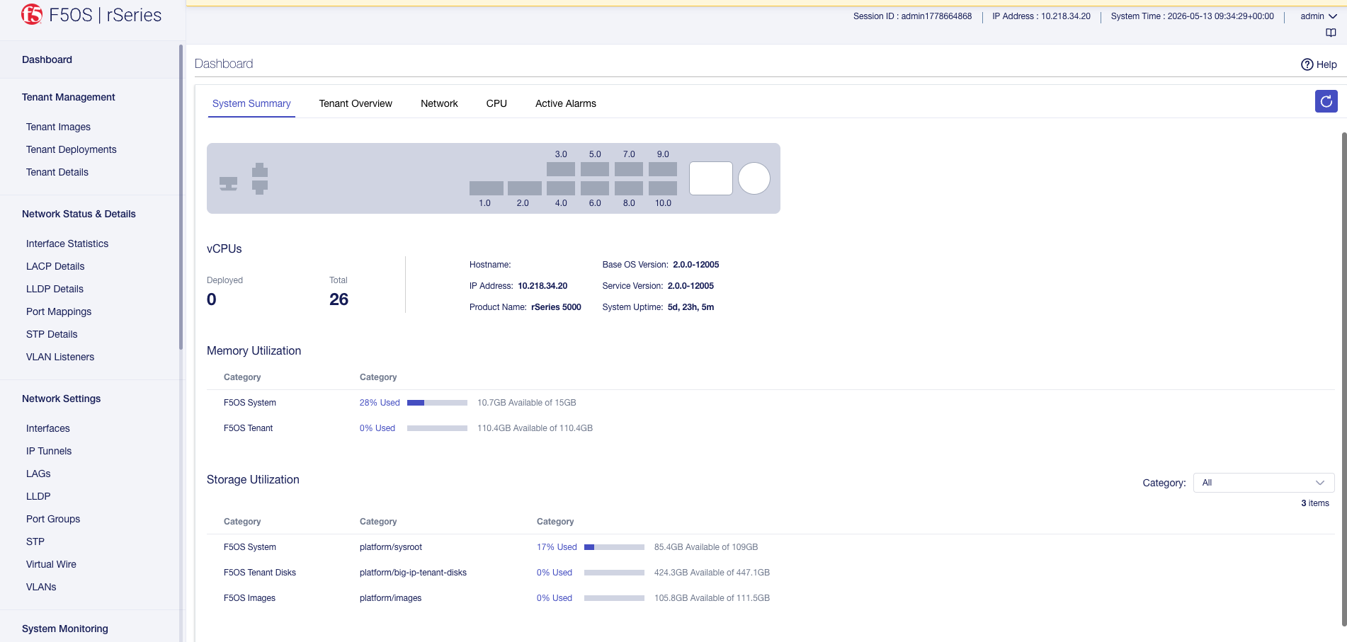
From a web browser, log in to the system using the management IP address (for example, https://192.0.2.10) and the admin account.
The Dashboard displays a graphical view of the appliance interfaces (ports) and high-level information about vCPUs, memory utilization, CPU thread counts, active alarms, and tenants.
-
To get contextual online Help, click the button in the upper right.
Online Help for that particular screen displays.
-
To get an idea of the available menu items on the left, click on them.
Different sections in the menu let you manage networking, system settings, and user authentication and accounts.
When you are done exploring the webUI, continue with initial configuration tasks.
You can license a system using the automatic method from the webUI, as long as the system has Internet access.
-
Log in to the webUI using an account with admin access.
-
On the left, click System Settings > Licensing.
-
The registration keys are auto-populated. You can choose to overwrite fields with a new registration key by clicking Reactivate and overwriting the field.
-
For the Base Registration Key field, you can choose to overwrite with new key.
-
For the Add-On Keys field, you can choose to change these keys and press Enter key to add additional add-on keys.
-
For the Activation Method, select Automatic.
Note: If you want utilize a proxy server for the purpose of license installation, enter the Proxy Server URL (a valid IPv4, IPv6, or FQDN). If the proxy server requires authentication, enter the Proxy Username and Proxy Password. At the licensing level, the proxy configuration is not retained and is solely utilized for the activation of the specific license instance. Alternatively, you can utilize the proxy server configured at System Settings > System Security > iHealth Configuration for license installation.
-
Click Activate.
The End User License Agreement (EULA) displays.
-
-
Click Agree to accept the EULA.
The system is now licensed. If a base registration key or add-on key fails to activate, try re-activating the license or contact F5 Support at support.f5.com.
You can use the webUI to create VLANs. You can also associate physical interfaces or link aggregation groups (LAGs) with VLANs. If you do this, any host that sends traffic to an interface is logically a member of the VLAN or VLANs to which that interface or LAG belongs. You need to create required VLANs before you can deploy a tenant.
-
From a web browser, log in to the webUI using the IP address that you configured and the admin account.
-
On the left, click Network Settings > VLANs.
The screen shows VLANs that are configured for the system.
-
Click Add. The Add VLAN page form displays.
-
For VLAN ID, enter a number between 1-4094 for the VLAN.
The VLAN ID identifies the traffic from hosts in the associated VLAN for an associated interface or LAG.
-
For Name, enter a name for the VLAN.
Note: VLAN names must follow these rules:
- Start with an alphabetic character (Aa-Zz).
- Can be up to 56 characters in length.
- After the first character, can contain alphanumeric characters, periods (.), hyphens (-) and underscores (_).
- VLAN names must be unique.
-
Click Save & Create Another to create new VLAN.
-
Click Save & Close to save the configuration.
The VLAN is created and displayed in the VLAN list. You can use the VLANs when configuring interfaces, creating LAGs, and deploying tenants (one VLAN can be shared by more than one tenant).
You can use Software Management to add or delete software images from the webUI.
You must use HTTPS for image import.
-
Log in to the webUI using an account with admin access.
-
On the left, click System Settings > Software Management.
-
To import a Base OS image:
-
Click Import.
The Add Base OS Image screen displays.
-
For URL, enter the URL of the remote image server.
F5 recommends that the remote host be an HTTPS server with PUT/POST enabled and have a valid CA-signed certificate. You can opt to select the Ignore Certificate Warnings check box if you want to skip the certificate check.
-
For Username, type the user name for an account on the remote image server, if required.
-
For Password, type the password for the account, if required.
-
Select Ignore Certificate Warnings to skip the certificate check.
-
Click Add Image.
Note:
- Depending on the image file size and network availability, the import might take a few minutes. You can view progress of the file transfer under the Image Transfer Status area. When the import is successful, the software image is listed in the webUI.
- If you want to cancel an in-progress file transfer operation, click Cancel button.
-
You can view the following information
- View the status of image imports under Image Transfer Status, which shows information about Remote Host, File, Status, and Time.
- Status of Cluster upgrade under Cluster Install Status, which include Stage, Status, Timestamp, Version and Description. Click Show to display the information.
- Status of Firmware upgrade under Firmware Install Status, which include Name, Installed Version, Desired Version, Configurable state, Update Status, and Restart Required. Click Show to display the information.
Note: If you perform an invalid operation, a runtime error displays in the Image Transfer status area.
You must have imported the tenant images that you want to use for the tenant deployments into the system. You must also have previously created any required VLANs. Before you can create and deploy tenants, you also need to estimate resource requirements so you know how many vCPUs, memory, and other resources to assign to the tenant.
An administrator can deploy tenants from the webUI. You can open a preview pane with tenant details by clicking anywhere in a row. You can resize the preview pane to show more or less information. To close the preview pane, click Close or click again anywhere in the row.
-
Log in to the webUI using an account with admin access.
-
On the left, click Tenant Management > Tenant Deployments.
The Tenant Deployment screen displays showing the existing tenant deployments and associated details.
-
To add a tenant deployment, click Add.
The Add Tenant Deployment screen displays.
-
For Name, enter a name for the tenant deployment (up to 49 characters).
Note: The first character in the name cannot be a number. After that, only lowercase alphanumeric characters and hyphens are allowed.
-
For Type, select the tenant type: BIG-IP.
-
For Image, select the software image that was previously imported onto the system.
Ensure that the image you selected meets your tenant deployment needs.
-
For IP Address, enter the IPv4 address, IPv6 address, or Fully Qualified Domain Name (FQDN) for the tenant.
-
For Prefix Length, enter a number for the length of the prefix.
The maximum prefix length is 32 for IPv4 and 128 for IPv6.
-
For Gateway, enter the IPv4 address or IPv6 address of the gateway.
-
For Management VLAN, select a management VLAN from the dropdown.
-
For VLANs, select one or more VLANs that are available to the tenant.
You can assign VLANs to more than one tenant.
-
For Virtual Wires, select configured virtual wires for the tenant.
Note: The Virtual Wires field is only available for selection when virtual wires have been configured
-
For MAC Data/MAC Block Size, select one of these options:
Option Description One Represents a block with one MAC. This is used when a contiguous block of MAC addresses is needed. This is the default value. Small Represents a block of 8 MACs. When this value is used, the tenant gets a block of 8 contiguous MACs. Medium Represents a block of 16 MACs. When this value is used, the tenant gets a block of 16 contiguous MACs. Large Represents a block of 32 MACs. When this value is used, the tenant gets a block of 32 contiguous MACs. -
For DAG IPv6 Prefix Length, enter the prefix length used by disaggregator algorithms.
The range is from 1 to 128, with a default value of 128.
For more information about the prefix length, see Configure DAG IPv6 prefix length from the CLI.
-
For Resource Provisioning, select one of these options:
Option Description Recommended Recommended values for vCPUs and memory for the tenant. Advanced Enables you to configure custom values for vCPUs and memory on the tenant. For example, if you want to configure a single vCPU tenant, or a tenant that uses more than the recommended amount of memory. -
For vCPUs, select the number of vCPUs to provide to the tenant
The minimum recommended number of vCPUs per typical tenant is two (one vCPU is sufficient only for lightweight tenants that cannot be updated). The number of vCPUs needed depends on the amount of traffic the tenant will be handling. More vCPUs provide faster throughput.
-
For Memory, specify the amount of RAM, in MB, to allocate to the tenant.
The amount of memory needed depends on the number of vCPUs assigned. The minimum amount of memory needed is determined by the formula
[(3.5 * 1024 * #ofvCPUs) + 512].Note: If you do not allocate sufficient memory, you may receive a warning message.
-
For Virtual Disk Size, specify the storage quota, in GB, for the tenant virtual disk.
Default size depends on the image type used. The default size for the ALL image is 82GB.
The minimum recommended disk size is 45 GB.
-
For State, select one of these options:
Options
Description
Configured
The tenant configuration exists on the system, but the tenant is not running, and no hardware resources (CPU, memory) are allocated to it. This is the initial state and the default.
Provisioned
Moves the tenant into the Provisioned state, which causes the system to install the software, assign the tenant to nodes, and create virtual disks for the tenant on those nodes. If you choose this option, it takes a few minutes to complete the provisioning. The tenant does not run while in this state.
Deployed
Changes the tenant to the Deployed state. The tenant is set up, resources are allocated to the tenant, the image is moved onto the system, the software is installed, and after those tasks are complete, the tenant is fully deployed and running. If you choose this option, it takes a few minutes to complete the deployment and bring up the system. Note: Once a tenant is Deployed (and is up and running), changing its state back to Configured or Provisioned stops the tenant. You will receive a warning message before this occurs.
-
For Crypto/Compression Acceleration, select Enabled if the tenant requires high-performance crypto processing and compression.
When this option is enabled, the tenant receives dedicated crypto devices proportional to the number of vCPU cores. Crypto processing and compression are off-loaded to the hardware. When the option is disabled, the tenant receives no crypto devices.
-
To restrict usage of the Bash shell for tenant administrators, set Appliance Mode to Enabled (this is Disabled by default.)
-
Click Save.
The tenant is now configured and in the Deployed state. When the status says Running, the tenant administrator can log in to the tenant webUI or CLI using the management IP address (with HTTPS or SSH) and continue configuring the tenant system.
Note: If the Status says Pending instead of Running, this may mean that there are not enough resources (vCPUs, memory, or other resources) for the tenant to be deployed. See the Tenant Details screen in the webUI for more information about the specific tenant.