Updated Date: 07/07/2026
Platform Maintenance
The r5000/r10000/r12000 Series platform contains components that you can replace individually without exchanging the entire system. This platform contains these replaceable components:
- AC power supply
- DC power supply
- Fan tray (r5000-DF/r10000/r12000S Series only)
- Storage drive (r5000-DF/r10000/r12000S only)
F5 platforms support up to two AC, DC, or high-voltage DC (HVDC) hot-swappable power supply units (PSUs). Some platforms come with only one PSU by default. This platform includes two PSUs by default.
CAUTION:
Running without power supply units (PSUs) installed in all available bays in the platform can affect cooling and electromagnetic interference (EMI). If you need to run the unit with one PSU, you must install a PSU blank into the empty PSU bay. The PSU blank is required to maintain proper airflow in the system. If you do not have a PSU blank, leave all supplies installed and disconnect power from any unused supplies.
CAUTION:
Do not mix power supply unit (PSU) models of different wattage. If two PSUs are installed in the same system, use only PSUs of the same wattage and part number.
Important: You should use only one power supply unit (PSU) type (AC, DC,) in a platform. AC/DC/ interoperability is not supported.
Important: This product is sensitive to electrostatic discharge (ESD). F5 recommends that you use proper ESD grounding procedures and equipment when you install or maintain the unit.
Note: Be sure to use only the power supply unit (PSU) that is designed for your platform. For example, a lower wattage PSU might not electrically connect if your platform is designed to use a higher wattage PSU.
Note: The power supply units (PSUs) do not have an on/off switch. Power is controlled from the rack switchor the mains power source.
Note: After removing input power from any power supply unit (PSU), wait 30 seconds before reapplying input power to the PSU.
This platform can support up to two AC power supply units (PSUs). You can hot swap a supply without powering down the system if there are two installed, and one remains installed and operational during the replacement process.
The platform supports PSU redundancy, which ensures that the system is unaffected if a single supply fails in a system with more than one operational supply installed.
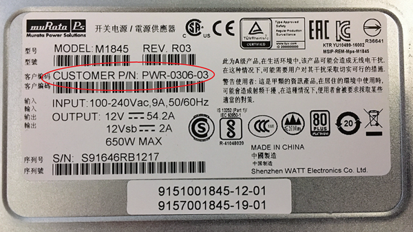
When you add or replace a supply in your system, be sure to verify the supply’s features and that the PWR-XXXX part numbers match to ensure that you have the correct supply.
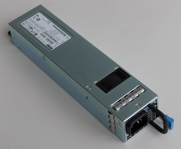
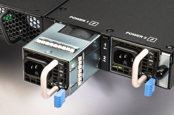
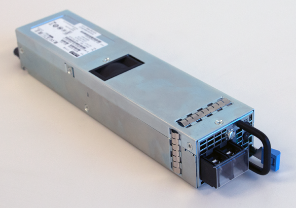
On the 650W PSU, you can find the part number on the top of the supply. For 650W AC, the part number is PWR-0306-xx, and for 650W DC, it is PWR-0307-xx. These supplies have a black vertical pull handle and a silver-colored power cord face with rectangle-shaped perforations.
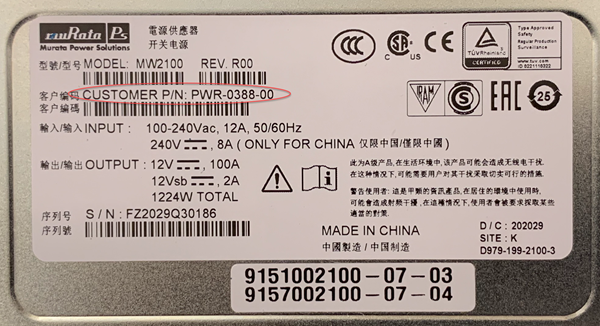
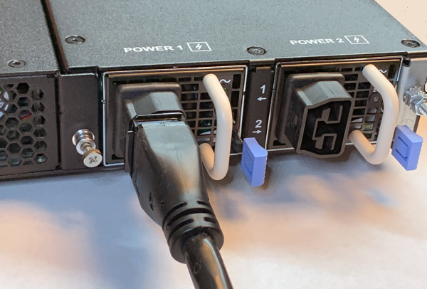
On the 1200W AC PSU, you can find the part number (PWR-0388-xx) on the top of the supply. These supplies have a cream-colored vertical pull handle and a black-colored power cord face with rectangle-shaped perforations.
CAUTION:
As a safety precaution, the socket outlet must be installed near the equipment and be easily accessible.
Important: You should use only one power supply unit (PSU) type (AC, DC,) in a platform. AC/DC/ interoperability is not supported.
In the event of a power supply unit (PSU) failure, you can replace an AC PSU in your system. For a dual-supply system, you can perform the replacement without powering down the system, provided that there is at least one PSU operating during the replacement process.
CAUTION:
Be sure that you are using the correct wattage and part number (PWR-0306-xxPWR-0388-xx) of power supply unit (PSU) in all bays, as applicable, when performing a PSU replacement.
Note: All photos shown are examples. The appearance of your power supply units (PSUs) might vary slightly, but be sure to use the pull handle orientation and perforations in the power cord face to verify the correct PSU for your platform.
-
Prepare the system for PSU replacement:
- For a single-supply system, power off the system.
- For a dual-supply system, make sure that you have an operational supply already installed in your system if you want to hot swap a supply while the system is running. If you do not want to hot swap, you can perform the replacement with the system powered off.
-
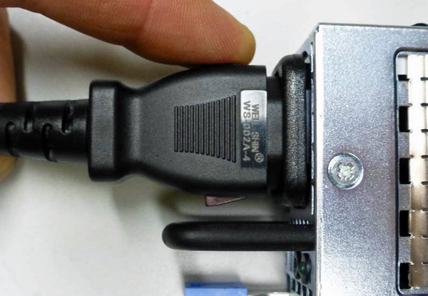
Before removing the PSU from your system, disconnect the AC power cord (input connector) from the PSU by pulling one or both of the power cord locking tabs away from the supply.
Important: Locking AC power cords might not be available in all countries.
-
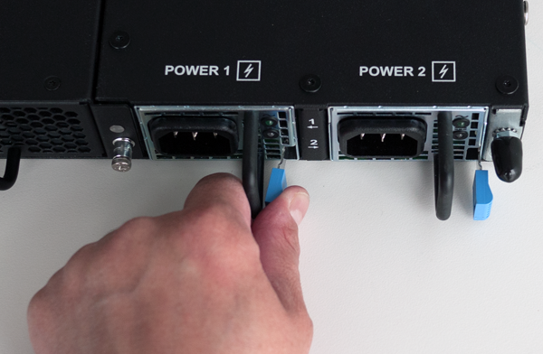
Remove the failed AC PSU by squeezing the ejector latch and pulling the handle straight toward you.
Note: After you remove a power supply unit (PSU) from the system, wait at least 30 seconds before you reinstall the PSU. Allow the PSU to fully discharge before you reinstall it.
-
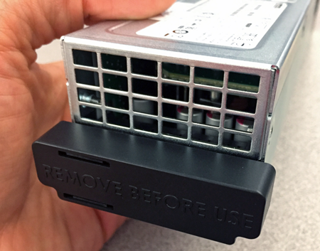
If an output connector protective cap is installed on your new PSU, remove it before installing the PSU into your system.
-
Inspect the new PSU, especially the connector area and pins, for any damage that might have occurred during shipment.
-
Slide the new PSU into the empty slot, and push it in until the ejector latch engages and clicks.
Note: While installing the supply, use care to ensure that the supply’s connector does not come into contact with the rear of the chassis.
-
Ensure that the PSU is fully seated in the chassis by making sure it does not come out when gently pulled.
-
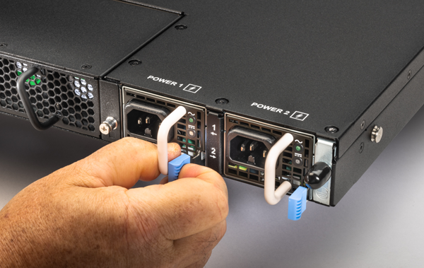
Insert the auto locking AC power cord into the PSU input connector and press firmly until it is fully seated.
Note: Be sure to route the power cords away from the fan tray so that the cords do not impede access to it.
-
Connect the power cord to the power source.
Note: If the system is fully powered down and does not boot after you apply power to the PSU, use the touchscreen LCD to power on the system.
-
Use the LCD touchscreen to clear any alert messages that might have resulted from performing the PSU replacement.
This platform can support up to two high-voltage DC (HVDC) power supply units (PSUs). You can hot swap PSUs without powering down the system if there are two installed and one remains installed and operational during the replacement process.
The platform supports power redundancy, which ensures that the system is unaffected if a single supply fails in a system with more than one operational supply installed.
On the 650W HVDC PSU, you can find the part number (PWR-0378-xx) on the top of the supply.
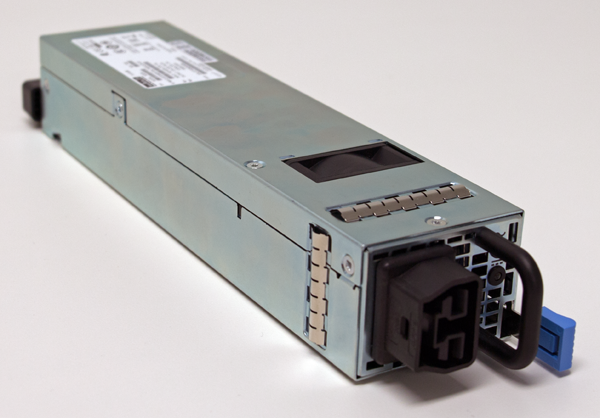
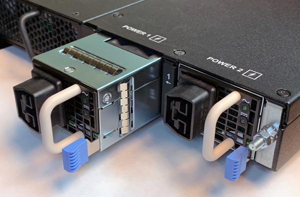
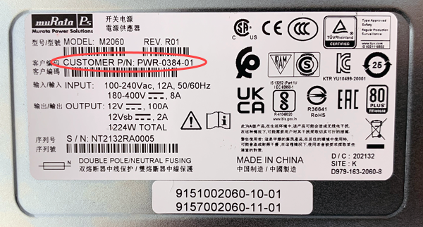
On the 1200W HVDC PSU, you can find the part number (PWR-0384-xx) on the top of the supply.
Important: You should use only one power supply unit (PSU) type (AC, DC,) in a platform. AC/DC/ interoperability is not supported.
Important: The platform must be installed in a RESTRICTED ACCESS LOCATION, such as a central office or customer premises environment.
Note: After removing input power from any power supply unit (PSU), wait 30 seconds before reapplying input power to the PSU.
You can upgrade your AC-powered or standard DC-poweredsystem with high-voltage DC (HVDC) power supply units (PSUs). In this case, you must install two HVDC PSUs, even if your system previously included only one PSU. You can also replace failed HVDC PSUs with replacement HVDC PSUs.
For a dual-supply system, you can perform the replacement without powering down the system, provided that there is at least one PSU operating during the replacement process.
CAUTION:
Be sure that you are using the correct wattage and part number (PWR-0384-xx) of power supply unit (PSU) in all bays, as applicable, when performing a PSU replacement.
Note: All photos shown are examples. The appearance of your power supply units (PSUs) might vary slightly, but be sure to use the pull handle orientation and perforations in the power cord face to verify the correct PSU for your platform.
-
Prepare the system for PSU replacement:
- For a single-supply system, power off the system.
- For a dual-supply system, make sure that you have an operational supply already installed in your system if you want to hot swap a supply while the system is running. If you do not want to hot swap, you can perform the replacement with the system powered off.
-
Be sure that the circuit breaker for the HVDC mains power source is switched off.
-
Remove the failed HVDC PSU by squeezing the ejector latch and pulling straight toward you.
Note: After you remove a power supply unit (PSU) from the system, wait at least 30 seconds before you reinstall the PSU. Allow the PSU to fully discharge before you reinstall it.
-
If an output connector protective cap is installed on your new PSU, remove it before installing the PSU into your system.
-
Inspect the new PSU, especially the connector area and pins, for any damage that might have occurred during shipment.
-
Slide the new PSU into the empty slot, and push it in until the ejector latch engages and clicks.
Note: While installing the supply, use care to ensure that the supply’s connector does not come into contact with the rear of the chassis.
-
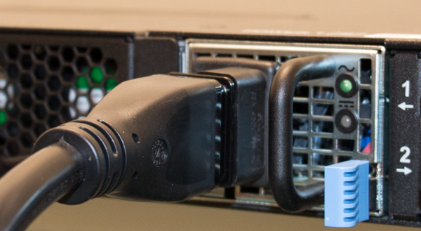
Insert the auto locking HVDC power cord into the PSU input connector and press firmly until it is fully seated.
Note: Be sure to route the power cords away from the fan tray so that the cords do not impede access to it.
-
Ensure that the PSU is fully seated in the chassis by making sure it does not come out when gently pulled.
-
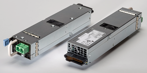
Connect the three ring terminals on the end of the cord to an approved power source.
The -L wire connects to the negative terminal of an approved source, the +N wire connects to the positive terminal of an approved source, and the ground wire connects to Earth/Ground.
-
Reapply input power from HVDC mains power source by switching the circuit breaker back on.
Note: If the system is fully powered down and does not boot after you apply power to the PSU, use the touchscreen LCD to power on the system.
-
Use the LCD touchscreen to clear any alert messages that might have resulted from performing the PSU replacement.
This platform can support up to two DC power supply units (PSUs). You can hot swap PSUs without powering down the system if there are two installed and one remains installed and operational during the replacement process.
The platform supports power redundancy, which ensures that the system is unaffected if a single supply fails in a system with more than one operational supply installed.
On the 650W DC PSU, you can find the part number (PWR-0307-xx) on the top of the supply.
On the 1200W DC PSU, you can find the part number (PWR-0385-xx) on the top of the supply.
CAUTION:
Before installing a DC power supply unit (PSU), be sure that the circuit breaker for the DC mains power to the PSU is switched off.
CAUTION:
Before you begin to work with one of these platforms, refer to the DC-powered equipment environmental warnings for this platform and review any safety requirements for the facilities where the DC-powered platforms will be installed.
Important: You should use only one power supply unit (PSU) type (AC, DC,) in a platform. AC/DC/ interoperability is not supported.
Important: The platform must be installed in a RESTRICTED ACCESS LOCATION, such as a central office or customer premises environment.
Note: Copper cables used for grounding must meet appropriate safety standards.
Note: Bare conductors should be coated with an appropriate antioxidant before being crimped. Make sure to clean all unplated connectors, braided strap, and bus bars to a bright finish prior to coating them with the antioxidant.
Note: The platform must be grounded to a common bonding network (CBN).
Note: The battery return terminals on the platform are in an isolated DC return (DC-I) configuration.
Note: When you are running a redundant DC power supply configuration, F5 strongly recommends that each DC power supply unit (PSU) in the system receives power from independent DC main power sources with independent circuit breakers.
Note: After removing input power from any power supply unit (PSU), wait 30 seconds before reapplying input power to the PSU.
Before you perform a DC power supply unit (PSU) replacement, you need to provide these tools and components:
- 12 AWG copper cable long enough to reach from the platform to the DC power source
- Flat-head or Phillips head screwdriver
In the event of a power supply unit (PSU) failure, you can replace a DC PSU in your system. For a dual-supply system, you can perform the replacement without powering down the system, provided that there is at least one PSU operating during the replacement process.
CAUTION:
Be sure that you are using the correct wattage and part number (PWR-0385-xx) of power supply unit (PSU) in all bays, as applicable, when performing a PSU replacement.
Note: All photos shown are examples. The appearance of your power supply units (PSUs) might vary slightly, but be sure to use the pull handle and power cord face perforations colors to verify the correct PSU for your platform.
-
Prepare the system for PSU replacement:
- For a single-supply system, power off the system.
- For a dual-supply system, make sure that you have an operational supply already installed in your system if you want to hot swap a supply while the system is running. If you do not want to hot swap, you can perform the replacement with the system powered off.
-
Be sure that the circuit breaker for the DC mains power source is switched off.
-
Remove the failed DC PSU by squeezing the ejector latch and pulling straight toward you.
Note: After you remove a power supply unit (PSU) from the system, wait at least 30 seconds before you reinstall the PSU. Allow the PSU to fully discharge before you reinstall it.
-
If an output connector protective cap is installed on your new PSU, remove it before installing the PSU into your system.
-
Inspect the new PSU, especially the connector area and pins, for any damage that might have occurred during shipment.
-
Assemble the DC cable by connecting one of the included DC ring terminals to one end of each of your 12 AWG copper cables.
-
Remove the terminal cover.
-
Use a screwdriver to remove the screws from the DC power terminals.
-
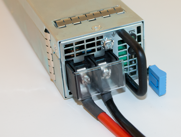
Connect the ring terminal for the positive (+) DC wire (typically red) to the left terminal, and the ring terminal for the negative (-) DC wire (typically black) to the right terminal.
-
After you have attached the ring terminals to the terminals, secure them using a screwdriver.
Use 13.5 inch-pounds (1.53 Newton-meters) of torque on these screws.
-
If the chassis is not connected to Earth ground, connect the power supply Earth ground terminal to Earth ground.
-
Verify that the DC power cables are connected to the appropriate terminal.
The red wire should be connected to the terminal labeled positive (+), and the black wire should be connected to the terminal labeled negative (-).
-
Replace the terminal cover.
-
Slide the new PSU into the empty slot, and push it in until the ejector latch engages and clicks.
Note: While installing the supply, use care to ensure that the supply’s connector does not come into contact with the rear of the chassis.
-
Ensure that the PSU is fully seated in the chassis by making sure it does not come out when gently pulled.
-
Reapply input power from DC mains power source by switching the circuit breaker back on.
-
Use the LCD touchscreen to clear any alert messages that might have resulted from performing the PSU replacement.
The fans in F5 platforms help maintain airflow throughout the chassis and run constantly while the unit is powered on. Over time, the fans can wear out, requiring you to replace the fan tray. For platforms that have a removable fan tray, you can change or replace the fan tray as part of the routine maintenance of the unit, or in the event of a fan failure.
Important: This product is sensitive to electrostatic discharge (ESD). F5 recommends that you use proper ESD grounding procedures and equipment when you install or maintain the unit.
To ensure that you can easily access the fan tray, route the power cords away from the fan tray so that the cords do not drape over or cross in front of it.
You do not need special tools and do not need to power down the unit when replacing the fan tray.
CAUTION:
Operating the unit without a fan tray for more than 30 seconds might result in performance throttling or a thermal shutdown of the unit.
-
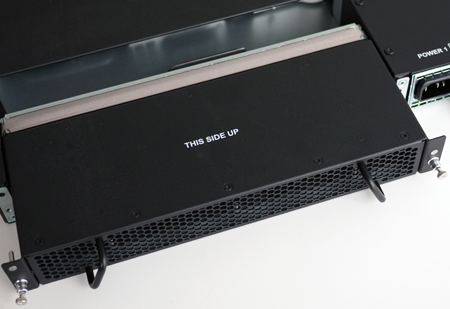
Locate the fan tray on the back of the chassis.
-
Loosen the fan tray screws by turning them counterclockwise with a Phillips screwdriver.
Note: The screws that hold the fan tray in place are captive and cannot be removed from the assembly.
-
Remove the fan tray from the chassis by grasping the handles and pulling straight toward you.
-
Slide the new fan tray into the fan tray slot.
-
Tighten the screws into place with a Phillips screwdriver.
Use 5 inch-pounds (0.6 Newton-meters) of torque on these screws. The fan tray is connected to the system when you tighten the screws completely. Once seated, the fan tray automatically powers up and begins circulating air through the chassis.
F5 r10000/r12000 Series platforms include two solid-state drives (SSDs) that are configured with RAID enabled. In the event of a drive failure, F5 sends you a new replacement drive for the faulty drive. For these platforms you do not need to power down the system when replacing a drive as part of routine maintenance or in the event of a drive failure.
Important: Replacement drives provided by F5 do not come pre-installed with software.
When performing a storage drive replacement, you must remove the failed drive from the software RAID array before physically removing the drive from the chassis.
Before you remove a faulty storage drive from your system, you should identify the faulty drive and remove it from the RAID array.
-
Connect to the system using a management console or console server.
Note: The default baud rate and serial port configuration is 19200/8-N-1.
-
Log in to the command line interface (CLI) of the system using an account with admin access.
When you log in to the system, you are in user (operational) mode.
-
Show the current status of the drives.
show system raid raid-array-statusA summary similar to this example displays:
appliance-1# show system raid raid-array-status
                                 ARRAY   ARRAY
NAME  BAYID  SERIAL NUMBER       MEMBER  STATUS     SIZE
----------------------------------------------------------
ssd1  0      PHLJ912345PK1P0FGN  true    ok         684.7G

ssd2  1      PHLJ912345Q61P0FGN  true    undefined  684.7G
The RAID array includes both storage drives as members. Note the serial number for the faulty drive and in which bay it is installed.
-
Change to config mode.
configThe CLI prompt changes to include
(config). -
Remove the faulty drive from the RAID array.
system raid remove drive ssd2A summary similar to this example displays:
appliance-1(config)# system raid remove drive ssd2
status Remove of RAID SSD2 initiated.
[11084.434517] md/raid1:md121: Disk failure on nvme1n1p3, disabling device.
[11084.434517] md/raid1:md121: Operation continuing on 1 devices.
[11084.449528] md/raid1:md122: Disk failure on nvme1n1p4, disabling device.
[11084.449528] md/raid1:md122: Operation continuing on 1 devices.
[11084.464098] md/raid1:md123: Disk failure on nvme1n1p5, disabling device.
[11084.464098] md/raid1:md123: Operation continuing on 1 devices.
[11084.478342] md/raid1:md124: Disk failure on nvme1n1p1, disabling device.
[11084.478342] md/raid1:md124: Operation continuing on 1 devices.
[11084.492509] md/raid1:md127: Disk failure on nvme1n1p2, disabling device.
[11084.492509] md/raid1:md127: Operation continuing on 1 devices.
status Remove of RAID SSD2 initiated.
Now you can physically remove the drive and replace it with the new one that you received from F5. You do not have to power down the system before you remove the drive.
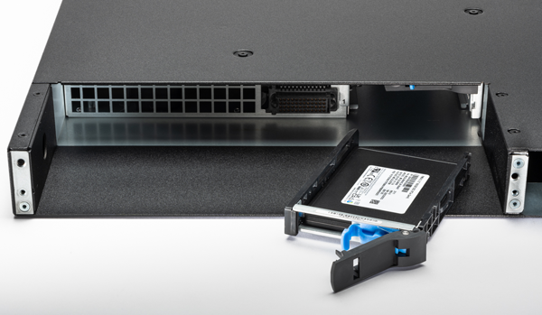
To physically access the storage drives, you must first remove the fan tray from the unit. Then you can remove the faulty drive from the chassis and replace the faulty drive with a new one from F5.
CAUTION:
To access the storage drive in this platform, you must remove the fan tray. Plan ahead to minimize the amount of time that the unit operates without a fan tray. Operating the unit at full load without a fan tray for more than 30 seconds might result in performance throttling or a thermal shutdown of the unit.
-
Locate the fan tray on the back of the chassis.
-
Loosen the fan tray screws by turning them counterclockwise with a Phillips screwdriver.
Note: The screws that hold the fan tray in place are captive and cannot be removed from the assembly.
-
Remove the fan tray from the chassis by grasping the handles and pulling straight toward you.
-
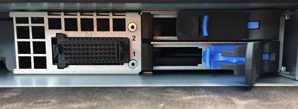
Verify the location of the faulty drive by identifying the drive bay that you noted earlier.
-
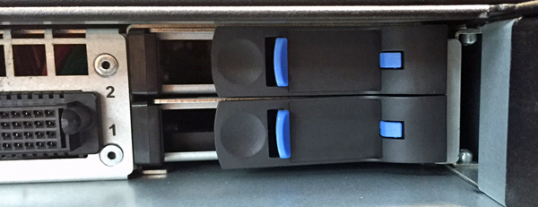
Remove the faulty drive by pushing the blue lever in the middle of the drive tray to the left.
Note: The bottom drive tray contains SSD1, and the top drive tray contains SSD2.
-
Pull the large latch straight toward you to eject the drive tray from the chassis.
-
Slide the new drive tray into the empty drive bay until the latch engages the chassis.
-
Push the latch inward toward the chassis until it clicks.
-
Slide the fan tray back into the fan tray slot.
-
Tighten the screws into place with a Phillips screwdriver.
Use 5 inch-pounds (0.6 Newton-meters) of torque on these screws. The fan tray is connected to the system when you tighten the screws completely. Once seated, the fan tray automatically powers up and begins circulating air through the chassis.
After you have physically replaced a faulty drive with a new one from F5, you add the replacement drive to the software RAID array.
-
Connect to the system using a management console or console server.
Note: The default baud rate and serial port configuration is 19200/8-N-1.
-
Log in to the command line interface (CLI) of the system using an account with admin access.
When you log in to the system, you are in user (operational) mode.
-
View the status of the drives.
show system raid raid-array-statusA summary similar to this example displays:
appliance-1# show system raid raid-array-status
                                 ARRAY   ARRAY
NAME  BAYID  SERIAL NUMBER       MEMBER  STATUS     SIZE
----------------------------------------------------------
ssd1  0      PHLJ912345PK1P0FGN  true    ok         684.7G

ssd2  1      PHLJ912345Q61P0FGN  true    undefined  684.7G
The status of the replacement drive is
undefined, and the serial number should match that of the replacement drive.Note: If after a few seconds, you do not see the replacement drive in the disk summary, the drive might not be seated properly. If this occurs, remove and reinsert the drive.
-
Change to config mode.
configThe CLI prompt changes to include
(config). -
Add the replacement drive to the array.
system raid add drive ssd2A summary similar to this example displays:
appliance-1(config)# system raid add drive ssd2
status Add RAID SSD2 initiated.
The array status for the new drive should change to
replicating, and the STAT LED should change to solid green. The replication process typically takes between 15 and 45 minutes. -
Return to user (operational) mode.
end -
Verify that the new drive is added to the RAID array.
show system raid raid-array-statusA summary similar to this example displays:
appliance-1# show system raid raid-array-status ARRAY ARRAY NAME BAYID SERIAL NUMBER MEMBER STATUS SIZE ---------------------------------------------------------- ssd1 0 PHLJ912345PK1P0FGN true ok 684.7G ssd2 1 PHLJ967890Q61P0FGN true ok 684.7G -
Check if there are any active system alarms.
show system alarmsIf there are any active alarms, they display in a summary similar to this example:
appliance-1# show system alarms
ID     RESOURCE  SEVERITY  TEXT                          TIME CREATED
--------------------------------------------------------------------------------------------
66306  lcd       ERROR     Fault detected in LCD module  2021-11-11 10:11:28.602630317 UTC