Manual Chapter :
Platform Maintenance
Applies To:
Show Versions
Platform Maintenance
About maintaining the platform
The
i5000/i7000/i10000/i11000 Series
platform contains components that you can replace individually without
exchanging the entire system. This platform contains these replaceable
components:- AC power supply
- DC power supply
- Fan tray(i7000/i10000/i11000 Series only)
- Storage drive(i7000/i10000/i11000 Series only)
About power supply units (PSUs)
The
i5000/i7000/i10000/i11000 Series
platform
supports up to two AC or DC
hot-swappable power supply units (PSUs). Most platforms come with only one PSU by default.
Running without power supply units (PSUs) installed in
all available bays in the platform can affect cooling and electromagnetic
interference (EMI). If you need to run the unit with one PSU, you must install
a PSU blank into the empty PSU bay. The PSU blank is required to maintain
proper airflow in the system. If you do not have a PSU blank, leave all
supplies installed and disconnect power from any unused supplies.
Do not mix power supply unit (PSU) models of different
wattage. If two PSUs are installed in the same system, use only PSUs of the
same wattage and part number.
You should use only one power supply unit (PSU) type (AC
or DC) in a platform. AC and DC interoperability is not supported.
This product is sensitive to electrostatic discharge
(ESD). F5 recommends that you use proper ESD grounding procedures and
equipment when you install or maintain the unit.
Be sure to use only the power supply unit (PSU) that is
designed for your platform. For example, a lower wattage PSU might not
electrically connect if your platform is designed to use a higher wattage
PSU.
The power supply units (PSUs) do not have an on/off
switch. Power is controlled from the rack switch
or the mains power source
.After removing input power from any power supply unit
(PSU), wait 30 seconds before reapplying input power to the PSU.
About AC power supply units (PSUs)
This platform can support up to two AC power supply units
(PSUs). You can hot swap a supply without powering down the system if there
are two installed, and one remains installed and operational during the
replacement process.
The platform supports power supply redundancy, which ensures
that the system is unaffected if a single supply fails in a system containing
more than one operational supply.
When you add or replace a power supply unit in your system,
be sure to verify the supply's features and that the PWR-XXXX part numbers
match to ensure that you have the correct supply.
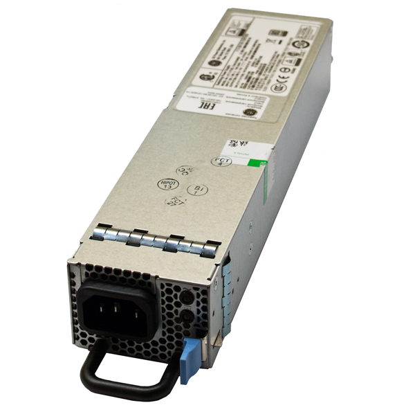
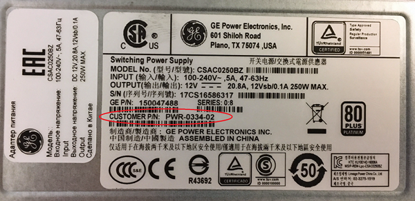
On the 250W AC PSU, you can find the
part number (PWR-0334-XX) on the top of the supply. This supply also has a
horizontal pull handle and hexagon-shaped perforations in the power cord
face.
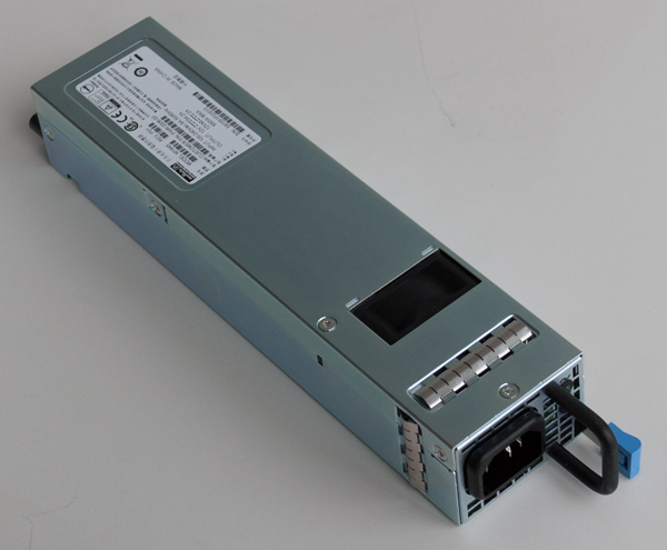
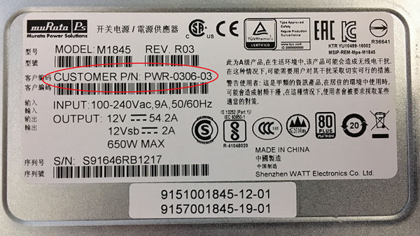
On the 650W PSU, you can find
the part number on the top of the supply. For 650W AC, the part number is
PWR-0306, and for 650W DC, it is PWR-0307. This supply also has a vertical
pull handle and rectangle-shaped perforations in the power cord face.
The 250W AC power supply unit (Platform:
i800/i2000/i4000; Part number: PWR-0334-xx)
Example of label to check PWR-XXXX part
number
The 650W AC power supply unit (Platform:
i5000/i7000/i10000/i11000; Part number: PWR-0306-xx)
Example of label to check PWR-XXXX part
number
As a safety precaution, the socket
outlet must be installed near the equipment and be easily accessible.
Replace an AC power supply
In the event of a power supply unit
(PSU) failure, you can replace an AC PSU in your system. For a dual-supply
system, you can perform the replacement without powering down the system,
provided that there is at least one PSU operating during the replacement
process.
Be sure that you are using the correct wattage and part
number (PWR-XXXX) of power supply unit (PSU) in all bays, as applicable, when
performing a PSU replacement.
All photos shown are examples. The appearance of your
power supply units (PSUs) might vary slightly, but be sure to use the pull
handle orientation and perforations in the power cord face to verify the
correct PSU for your platform.
- Prepare the system for PSU replacement:
- For a single-supply system, use the touchscreen LCD to halt and power off the system.
- For a dual-supply system, make sure that you have an operational supply already installed in your system if you want to hot swap a supply while the system is running. If you do not want to hot swap, you can perform the replacement with the system powered off.
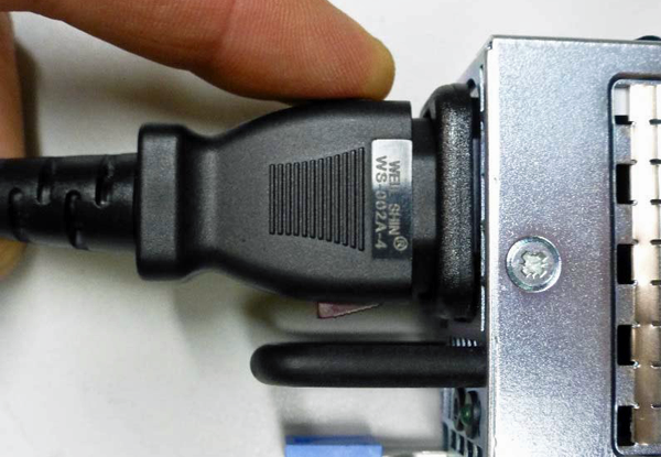
- Before removing the PSU from your system, disconnect the AC power cord (input connector) from the power supply by pulling one or both of the power cord locking tabs away from the power supply.Locking AC power cords might not be available in all countries.
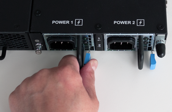
- Remove the failed AC PSU by squeezing the ejector latch and pulling the handle straight toward you.
 After you remove a power supply unit (PSU) from the system, wait at least 30 seconds before you reinstall the PSU. Allow the PSU to fully discharge before you reinstall it.
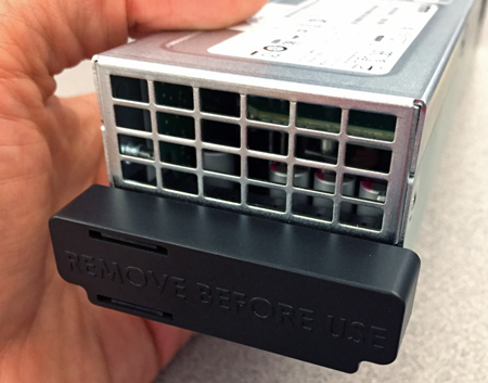
 - If an output connector protective cap is installed on your new PSU, remove it before installing the PSU into your system.
- Inspect the new PSU, especially the connector area and pins, for any damage that might have occurred during shipment.
- Slide the new PSU into the empty slot, and push it in until the ejector latch engages and clicks.While installing the supply, use care to ensure that the supply's connector does not come into contact with the rear of the chassis.
- Ensure that the PSU is fully seated in the chassis by making sure it does not come out when gently pulled.
- Insert the auto locking AC power cord into the PSU input connector and press firmly until it is fully seated.Be sure to route the power cords away from the fan tray so that the cords do not impede access to it.
- Connect the power cord to the power source.If the system is fully powered down and does not boot after you apply power to the PSU, use the touchscreen LCD to power on the system.
- Use the LCD touchscreen to clear any alert messages that might have resulted from performing the PSU replacement.
About DC power supply units (PSUs)
This platform can support up to two DC power supply units (PSUs). You
can hot swap PSUs without powering down the system if there are two
installed and one remains installed and operational during the replacement
process.
The platform supports power redundancy, which ensures that
the system is unaffected if a single supply fails in a system containing
more than one power supply.
Your platform must be running
BIG-IP
software versions 12.1.1 HF2,
12.1.2, or later to support DC power.The 650W DC power supply unit (Platform:
i5000/i7000/i10000/i11000
; Part number:
PWR-0307-xx)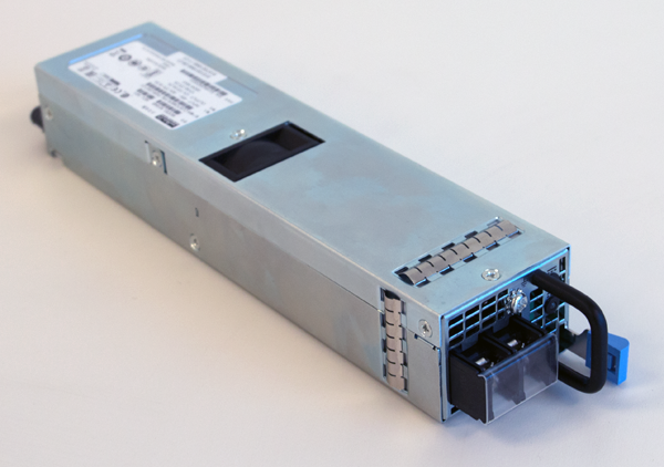
Before installing a DC power supply unit (PSU), be sure
that the circuit breaker for the DC mains power to the PSU is switched
off.
Before you begin to work with one of
these platforms, refer to the DC-powered equipment environmental warnings for
this platform and review any safety requirements for the facilities where the
DC-powered platforms will be installed.
You should use only one power supply unit (PSU) type (AC
or DC) in a platform. AC and DC interoperability is not supported.
The platform must be installed in a RESTRICTED ACCESS
LOCATION, such as a central office or customer premises environment.
Copper cables used for grounding must meet
appropriate safety standards.
Bare conductors should be coated with an
appropriate antioxidant before being crimped. Make sure to clean all unplated
connectors, braided strap, and bus bars to a bright finish prior to coating
them with the antioxidant.
The platform must be grounded to a common
bonding network (CBN).
The battery return terminals on the
platform are in an isolated DC return (DC-I) configuration.
When you are running a redundant DC power supply
configuration, F5 strongly recommends that each DC power supply unit (PSU) in
the system receives power from independent DC main power sources with
independent circuit breakers.
After removing input power from any power supply unit
(PSU), wait 30 seconds before reapplying input power to the PSU.
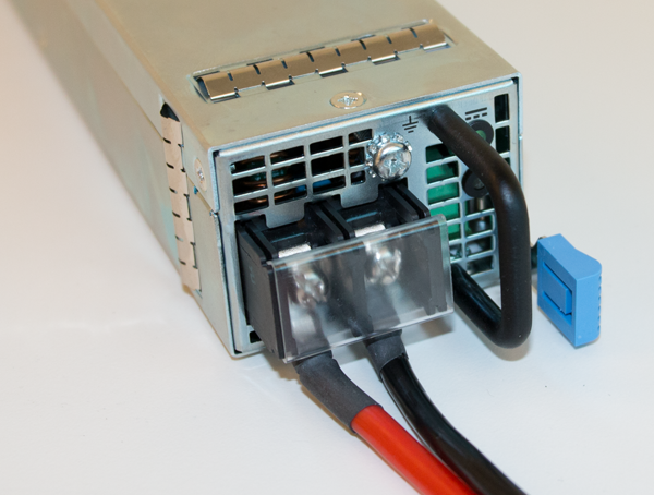
Replace a standard DC power supply unit (PSU)
Before you perform a DC power supply
unit (PSU) replacement, you need to provide these tools and components:
- 12 AWG copper cable long enough to reach from the platform to the DC power source
- Flat-head or Phillips head screwdriver
In the event of a power supply unit
(PSU) failure, you can replace a DC PSU in your system. For a dual-supply
system, you can perform the replacement without powering down the system,
provided that there is at least one PSU operating during the replacement
process.
Be sure
that you are using the correct wattage and part number (PWR-0307-xx) of
power supply unit (PSU) in all bays, as applicable, when performing a
power supply replacement.
All photos shown are examples. The appearance of your
power supply units (PSUs) might vary slightly, but be sure to use the pull
handle orientation and perforations in the power cord face to verify the
correct PSU for your platform.
- Prepare the system for PSU replacement:
- For a single-supply system, use the touchscreen LCD to halt and power off the system.
- For a dual-supply system, make sure that you have an operational supply already installed in your system if you want to hot swap a supply while the system is running. If you do not want to hot swap, you can perform the replacement with the system powered off.
- Be sure that the circuit breaker for the DC mains power source is switched off.
- Remove the failed DC PSU by squeezing the ejector latch and pulling straight toward you.After you remove a power supply unit (PSU) from the system, wait at least 30 seconds before you reinstall the PSU. Allow the PSU to fully discharge before you reinstall it.
- If an output connector protective cap is installed on your new PSU, remove it before installing the PSU into your system.
- Inspect the new PSU, especially the connector area and pins, for any damage that might have occurred during shipment.
- Assemble the DC cable by connecting one of the included DC ring terminals to one end of each of your 12 AWG copper cables.
- Remove the terminal cover.
- Use a screwdriver to remove the screws from the DC power terminals.
- Connect the ring terminal for the positive (+) DC wire (typically red) to the left terminal, and the ring terminal for the negative (-) DC wire (typically black) to the right terminal.
- After you have attached the ring terminals to the terminals, secure them using a screwdriver.Use 13.5 inch-pounds (1.53 Newton-meters) of torque on these screws.
- If the chassis is not connected to Earth ground, connect the power supply Earth ground terminal to Earth ground.
- Verify that the DC power cables are connected to the appropriate terminal.The red wire should be connected to the terminal labeled positive (+), and the black wire should be connected to the terminal labeled negative (-).
- Replace the terminal cover.
- Slide the new PSU into the empty slot, and push it in until the ejector latch engages and clicks.While installing the supply, use care to ensure that the supply's connector does not come into contact with the rear of the chassis.
- Ensure that the PSU is fully seated in the chassis by making sure it does not come out when gently pulled.
- Reapply input power from DC mains power source by switching the circuit breaker back on.
- Use the LCD touchscreen to clear any alert messages that might have resulted from performing the PSU replacement.
Replace a high voltage DC power
supply unit (PSU)
You can upgrade your AC-powered or
standard DC-powered system with high voltage DC (HVDC) power supply units
(PSUs). In this case, you must install two HVDC PSUs, even if your system
previously included only one PSU. You can also replace failed HVDC PSUs with
replacement HVDC PSUs.
For a dual-supply system, you can
perform the replacement without powering down the system, provided that
there is at least one PSU operating during the replacement process.
Be sure that you
are using the correct wattage and part number (PWR-0378-xx) of power
supply unit (PSU) in all bays, as applicable, when performing a power
supply replacement.
All photos shown are examples. The appearance of your
power supply units (PSUs) might vary slightly, but be sure to use the pull
handle orientation and perforations in the power cord face to verify the
correct PSU for your platform.
- Prepare the system for PSU replacement:
- For a single-supply system, use the touchscreen LCD to halt and power off the system.
- For a dual-supply system, make sure that you have an operational supply already installed in your system if you want to hot swap a supply while the system is running. If you do not want to hot swap, you can perform the replacement with the system powered off.
- Be sure that the circuit breaker for the DC mains power source is switched off.
- Remove the failed HVDC PSU by squeezing the ejector latch and pulling straight toward you.After you remove a power supply unit (PSU) from the system, wait at least 30 seconds before you reinstall the PSU. Allow the PSU to fully discharge before you reinstall it.
- If an output connector protective cap is installed on your new PSU, remove it before installing the PSU into your system.
- Inspect the new PSU, especially the connector area and pins, for any damage that might have occurred during shipment.
- Insert the auto locking HVDC power cord into the PSU input connector and press firmly until it is fully seated.
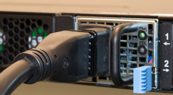 Be sure to route the power cords away from the fan tray so that the cords do not impede access to it.
 - Ensure that the PSU is fully seated in the chassis by making sure it does not come out when gently pulled.
- Connect the three ring terminals on the end of the cord to an approved power source.The blue wire (-L) connects to the negative terminal of an approved source, the brown wire (+N) connects to the positive terminal of an approved source, and the yellow/green wire connects to earth/ground.
- Reapply input power from DC mains power source by switching the circuit breaker back on.If the system is fully powered down and does not boot after you apply power to the PSU, use the touchscreen LCD to power on the system.
- Use the LCD touchscreen to clear any alert messages that might have resulted from performing the PSU replacement.
About the fan tray
The
iSeries/rSeries
platforms have a removable fan tray
that is designed to maintain airflow throughout the chassis. You can change or
replace the fan tray as part of the routine maintenance of the unit, or in the
event of a fan failure. The fans in the fan tray run constantly while the unit
is powered on. Over time, the fans can wear out, requiring you to replace the
fan tray.The
i7000/i10000/i11000 Series
fan tray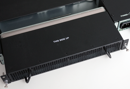
This product is sensitive to electrostatic discharge
(ESD). F5 recommends that you use proper ESD grounding procedures and
equipment when you install or maintain the unit.
Replace the fan tray
To ensure that you can easily access
the fan tray, route the power cords away from the fan tray so that the cords
do not drape over or cross in front of it.
You do not need special tools and
do not need to power down the unit when replacing the fan tray.
Operating the unit without a fan tray for more than 30
seconds might result in performance throttling or a thermal shutdown of the
unit.
- Locate the fan tray on the back of the chassis.
- Loosen the fan tray screws by turning them counterclockwise with a Phillips screwdriver.The screws that hold the fan tray in place are captive and cannot be removed from the assembly.
- Remove the fan tray from the chassis by grasping the handles and pulling straight toward you.
- Slide the new fan tray into the fan tray slot.
- Tighten the screws into place with a Phillips screwdriver.Use 5 inch-pounds (0.6 Newton-meters) of torque on these screws. The fan tray is connected to the system when you tighten the screws completely. Once seated, the fan tray automatically powers up and begins circulating air through the chassis.
About storage drive options
For
BIG-IP
platforms that
include one or two solid-state drives (SSDs), you can replace drives in the
event of a drive failure.Platform model |
Single solid-state drive |
Dual solid-state drives |
|---|---|---|
i7000 |
i7000 |
i7000-D |
i10000 |
i10000 |
i10000-D |
i11000 |
i11000 |
N/A |
About replacing a drive in single-drive system
For iSeries platforms that include only one drive by
default, the drive is located in drive bay 1, and you must install the
replacement drive back into drive bay 1. You must also power down the system
when replacing a drive as part of routine maintenance or in the event of a
drive failure.
The replacement storage drive
provided by
F5
does not come with
pre-installed software. You will need to create a bootable USB flash drive to
install software onto the drive. Alternately, you can use a PXE server to
install the software. For more information, see K13117: Performing a clean
installation of BIG-IP 11.x - 16.x.Prerequisites for replacing a
single drive
Before you replace a storage drive in a single-drive system, you need:
- A USB flash drive with a storage capacity that exceeds the size of the desiredF5software ISO image
- AnF5software ISO image
- AnF5system or a Linux system that is used to create a bootable USB flash driveFor information on creating a bootable USB drive, seeF5 Platforms: Essentialsat techdocs.f5.com/en-us/hw-platforms/f5-plat-hw-essentials.html.
Replace a storage drive tray in a single-drive
system
You can remove the faulty drive
from the chassis and install the blank replacement drive that you received
from
F5
. You can access
the storage drives after removing the fan tray from the back of the chassis.
All photos shown are examples. The appearance of your
components or accessories might vary slightly.
- Locate the fan tray on the back of the chassis.
- Loosen the fan tray screws by turning them counterclockwise with a Phillips screwdriver.The screws that hold the fan tray in place are captive and cannot be removed from the assembly.
- Remove the fan tray from the chassis by grasping the handles and pulling straight toward you.
- Remove the faulty drive by pushing the lever in the middle of the drive tray to the left.
- Pull the large latch straight toward you to eject the drive tray from the chassis.
- Slide the new drive tray into the empty drive bay until the latch engages the chassis.
- Push the latch inward toward the chassis until it clicks.
- Slide the fan tray back into the fan tray slot.
- Tighten the screws into place with a Phillips screwdriver.Use 5 inch-pounds (0.6 Newton-meters) of torque on these screws. The fan tray is connected to the system when you tighten the screws completely. Once seated, the fan tray automatically powers up and begins circulating air through the chassis.
Bootable USB
flash drive creation on an iSeries system
You can use
mkdisk
,
which is included in the F5 software installation
ISO image file, to create a bootable USB flash drive that contains an
F5
software ISO image. You can then use
this bootable USB flash drive to install or upgrade a system when you either
do not have the installation image on the storage drive, or when you cannot
access the storage drive. Additionally, you can use the USB flash drive to
recover the system.Linux system requirements for creating a bootable USB flash drive
For each platform, you might need to provide additional peripheral
hardware. If you plan to remotely administer the system, it would be helpful to
have a workstation already connected to the same subnet as the management
interface.
Component |
Description |
|---|---|
Linux |
2.6.x kernel |
Perl |
Version 5.8 or later |
Library for WWW in Perl (LWP)
package |
Downloadable from www.cpan.org |
Create a bootable USB flash drive
You can create a bootable USB flash
drive that contains an F5 software ISO image using either an existing
F5
system that is running a recent
an F5
software release or a Linux
workstation that is running a recent Linux distribution.- Log in to the command line of the system using an account with root access.
- Mount the installation as a loopback device, using one of these methods:
- If you have anF5system with theF5ISO image located in the/shared/imagesdirectory:
- Create a new directory:mkdir /mnt/iso
- Mount the ISO image:mount –o loop BIGIP-<version>.iso /mnt/iso
- If you have a DVD drive attached to the system that contains a validF5software image, insert the DVD into the DVD drive.
- Insert a 2 GB or larger flash drive into a USB port on theF5system or Linux workstation.
- Change to the root directory to the mounted image.cd /mnt/iso
- Start themkdiskscript../mkdisk
- Respond to the series of questions that display by choosing the appropriate options for your configuration.
- Specify theF5system that you plan to use as the target for USB flash drive installation.
- Specify the device to be used bymkdisk(that is, the USB flash drive that you are creating).
- Confirm that you want to continue by typingy.
- Specify the product to transfer (for example, BIG-IP version 11.6.0) or typeyif there is only one product.
The script checks for the required tools and creates the flash drive. The flash drive creation process might take several minutes. - When the process is complete, unmount the ISO image.umount /mnt/iso
You can now remove the USB flash
drive and use it to boot other
F5
systems, as needed.Boot the iSeries
system from a bootable USB flash drive
iSeries
system from a bootable USB flash driveBefore you boot the F5 system to the
Maintenance OS (MOS), be sure that you have console access to the system,
either through a console server or directly through a serial connection.
Once you boot to the MOS, you lose
connection with the system over SSH on the management
port.
You can use a bootable USB flash
drive as the installation source to install or upgrade an
F5
system.- Insert the flash drive into the USB port of the target system.
- Boot the target system.The device automatically boots to the MOS on the attached USB flash drive.
About replacing a drive in a dual-drive system
For iSeries platforms that include two solid-state drives (SSDs) by default. These platforms support drive mirroring using RAID. For these platforms, you do not need to power down the system when replacing a drive as part of routine maintenance or in the event of a drive failure.
If a drive fails, please contact F5 Support for an entire box replacement.
Replacement drives provided by F5 do not come
pre-installed with software.
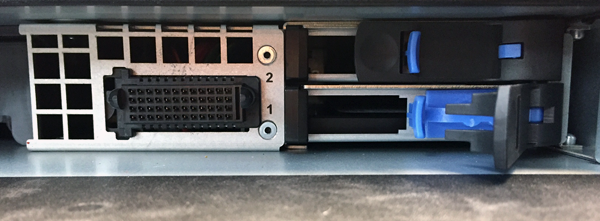
Identify the faulty storage
drive
To physically access the storage
drives, you must first remove the fan tray from the unit.
Before you remove a storage
drive from your system, you should identify the faulty drive.
- Open the TMOS Shell (tmsh).tmsh
- View the status of the drives.show sys raidA disk summary similar to this example displays:--------------------- Sys::Raid::Array: MD1 --------------------- Size (MB) 931.5K --------------------------------------------------------- Sys::Raid::ArrayMembers Bay ID Serial Number Name Array Member Array Status --------------------------------------------------------- 1 S2HSNX0HB02143 HD2 yes failed 2 S2HSNX0HB02237 HD1 yes ok ------------------------------------------------------------- Sys::Raid::Bay Bay Shelf Name Serial Number Array Member Array Status ------------------------------------------------------------- 1 1 HD2 S2HSNX0HB02143 yes failed 2 1 HD1 S2HSNX0HB02237 yes ok -------------------------------------------------------------------- Sys::Raid::Disk Name Serial Number Array Array Status Model Member -------------------------------------------------------------------- HD1 S2HSNX0HB02143 yes ok ATA SAMSUNG MZ7KM480 HD2 S2HSNX0HB02237 yes failed ATA SAMSUNG MZ7KM480
- Make note of the bay number and serial number for the faulty drive (the drive with thefailedstatus).The serial number is printed in its entirety on the labels on top of the drive.
- Before you remove the drive from the system, remove the faulty drive from the array.The faulty drive is HD2 in this example.modify sys raid array MD1 remove HD2
Now you can remove the drive and replace it with the new one that you
received from F5. You do not have to power down the system before you remove the drive.
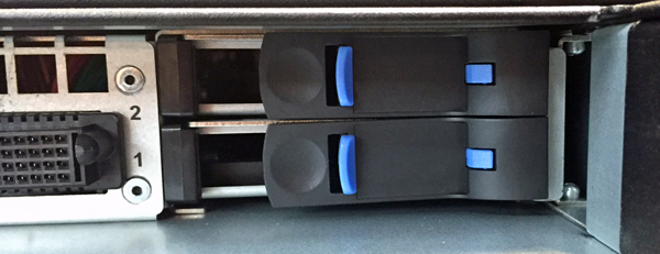
Replace a storage drive tray in
a dual-drive system
For dual drive systems, F5 sends you a
replacement drive to replace the failed drive. You can remove the faulty drive
from the chassis and install the blank replacement drive that you received
from
F5
. You can access
the storage drives after removing the fan tray from the back of the chassis.
All photos shown are examples. The appearance of your
components or accessories might vary slightly.
- Locate the fan tray on the back of the chassis.
- Loosen the fan tray screws by turning them counterclockwise with a Phillips screwdriver.The screws that hold the fan tray in place are captive and cannot be removed from the assembly.
- Remove the fan tray from the chassis by grasping the handles and pulling straight toward you.
- Verify the location of the faulty drive by comparing the drive bay that you noted earlier.
- Remove the faulty drive by pushing the lever in the middle of the drive tray to the left.Verify that the serial number that you noted earlier matches what is on the drive.
- Pull the large latch straight toward you to eject the drive tray from the chassis.
- Slide the new drive tray into the empty drive bay until the latch engages the chassis.
- Push the latch inward toward the chassis until it clicks.
- Slide the fan tray back into the fan tray slot.
- Tighten the screws into place with a Phillips screwdriver.Use 5 inch-pounds (0.6 Newton-meters) of torque on these screws. The fan tray is connected to the system when you tighten the screws completely. Once seated, the fan tray automatically powers up and begins circulating air through the chassis.
- View the status of the drives.tmsh show sys raid diskA disk summary, similar to this example, displays:------------------------------------------------------------- Sys::Raid::Disk Name Serial Number Array Array Status Model Member ------------------------------------------------------------- HD1 S2HSNX0HB02143 yes ok SAMSUNG MZ7KM480 HD2 S2HSNX0HB02237 yes undefined SAMSUNG MZ7KM480The status of the replacement drive isundefined, and the serial number should match that of the replacement drive.If after a few seconds, you do not see the additional drive in the disk summary, the drive might not be seated properly. If this occurs, remove and reinsert the drive.
- Add the replacement drive (HD2 in the example) to the array.tmsh modify sys raid array MD1 add HD2The status of the replacement drive should change toreplicating, and the STAT LED should change to solid green. The replication process typically takes between 15 and 45 minutes.


