Manual Chapter :
Platform Overview
Applies To:
Show Versions
Platform Overview
About i5000/i7000/i10000/i11000 Series models
i5000/i7000/i10000/i11000 Series
modelsThe
i5000/i7000/i10000/i11000 Series
platform is a powerful system that is designed
specifically for application delivery performance and scalability.The i5000 and i7000 Series platforms are
available with a FIPS-validated hardware security module (HSM) as a
factory-installed option (i5820-DF and i7820-DF). These platforms have dual
solid-state drives (SSDs).
The i15000F platforms (i15820-DF) are
available with a FIPS-validated hardware security module (HSM) as a
factory-installed option. These platforms have dual
solid-state drives (SSDs).
The i7000 and i10000 Series
platforms are available in a dual solid-state drive (SSD) configuration
(i7000-D and i10000-D).
The DC-powered
i7000/i10000/11000 Series platforms are available with either standard or high
voltage DC (HVDC) configuration. HVDC power supply units (PSUs) are available
as a field-installed upgrade option only on i7000/i10000/i11000 Series
platforms with these part numbers: 503-0030-xx to 503-0034-xx or 505-0030-xx
to 505-0031-xx.
The i10000 Series includes the i10010
platform, which includes a configuration with 100GbE and 40GbE network
connectivity (i10810 and i10610).
Verify the part
number of your platform by typing
tmsh
show sys hardware
on the command line. The part number is listed
in the "System Information" section.F5
offers three performance levels of SSL offload in
the i11000 Series: the i11800-DS, the i11600-DS, and the i11400-DS. All have
dual solid-state drives (SSDs) and feature high-performance SSL hardware that
frees servers from the task of encrypting and decrypting data.For more information, please see the data sheet at www.f5.com/pdf/products/big-ip-platforms-datasheet.pdf.
About the platform
Before you install this platform, review
information about the controls and ports located on both the front and back of the
platform.
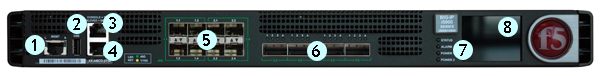
On the front of the platform, you can use the LCD
touchscreen to view information about, manage, and reset the system. You can
also use the front-panel LEDs to assess the condition of the system.
Front view of the i5000 platform
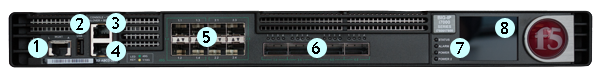
Front view of the i7000 Series
platform
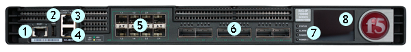
Front view of the i10000 Series
platform
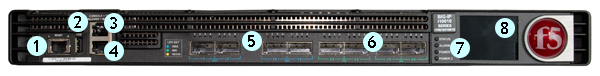
Front view of the i11000 Series
platform
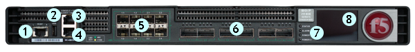
- 10/100/1000-BaseT capable management port
- Hi-Speed USB port
- Console serial port
- Serial (hard-wired) failover port
- 10GbE SFP+ ports (8)
- 40GbE QSFP+ ports (46)
- Indicator LEDs
- 2.2 inch LCD touchscreen
Front view of the i10010 platform
- 10/100/1000-BaseT capable management port
- Hi-Speed USB port
- Console serial port
- Serial (hard-wired) failover port
- 100GbE QSFP28 ports (4)
- 40GbE QSFP+ ports (4)
- Indicator LEDs
- 2.2 inch LCD touchscreen
The back of the
i5000
Series
platform includes one power supply, one power blank, and a
chassis ground terminal.Back view of the
i5000 Series
AC-powered platform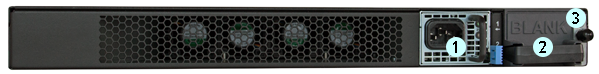
- Power input panel 1 (AC power receptacle)
- Power blank
- Chassis ground terminal
Back view of the i5000 Series DC-powered
platform
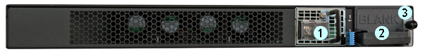
- Power input panel 1 (DC terminal)
- Power blank
- Chassis ground terminal
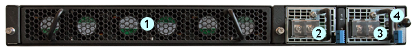
The back of the
iSeries/rSeries
platform includes the fan tray, two power supply
units (PSUs), a chassis ground terminal, and the storage drives (located
behind the fan tray).Back view of the i7000/i10000/i11000 Series
AC-powered platform
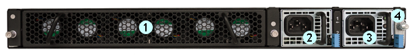
- Fan tray (removable)
- Power input panel 1 (AC power receptacle)
- Power input panel 2 (AC power receptacle)
- Chassis ground terminal
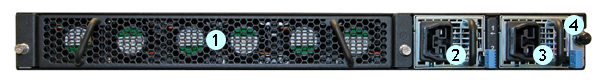
Back view of the i7000/i10000/i11000 Series
DC-powered platform
- Fan tray (removable)
- Power input panel 1 (DC terminal)
- Power input panel 2 (DC terminal)
- Chassis ground terminal
Back view of the i7000/i10000 Series High
Voltage DC-powered platform
- Fan tray (removable)
- Power input panel 1 (DC power receptacle)
- Power input panel 2 (DC power receptacle)
- Chassis ground terminal
Hardware
included with the platform
This platform includes all of the hardware
components listed here.
Quantity |
Hardware |
|---|---|
1 or 2 |
Power cables (black), AC power only,
per platform configuration. Might include multiple power cable
types if product is delivered outside of the US/Canada. By default, these platforms include
one power supply and power cable: i5000 Series. |
2 |
Power cables (black), AC power only,
per platform configuration. Might include multiple power cable
types if product is delivered outside of the
US/Canada. |
4 |
DC ring terminals, DC power only. By default, this
platform includes two DC power supply units (PSUs) and two ring terminals
per supply |
4 |
DC ring terminals, standard DC power
only. By default, this platform includes two DC power supply units (PSUs)
and four ring terminals. |
1 |
RJ45 to RJ45 failover cable, CAT 5
crossover (blue) |
1 |
RJ45 to DB9 console port cable
(beige) |
1 |
RJ45F to RJ45M rolled adapter
(beige) |
1 |
Quick-install rail kit |
2 |
Rail lock brackets |
4 |
M3 x 8mm flathead screws, black with
patch |
4 |
#8-32 pan head screws, steel zinc |
Peripheral hardware
required
For each platform, you might need to provide additional peripheral
hardware. If you plan to remotely administer the system, it would be helpful to
have a workstation already connected to the same subnet as the management
interface.
Type of hardware |
Description |
|---|---|
Network hubs, switches, or connectors to connect to the
platform network interfaces |
You must provide networking devices that are
compatible with the network interface ports on the platform.
You can use either 1000/10000-Megabit or 40-Gigabit
Ethernet switches.
|
External USB CD/DVD drive or USB flash drive |
You can use any USB-certified CD/DVD mass storage device or
a USB flash drive for installing upgrades and for system
recovery. External CD/DVD drives must be
externally powered. |
Serial console |
You can remotely manage the platform by connecting to a
serial console terminal server through the console port. In the event that network access is
impaired or not yet configured, the serial console might
be the only way to access the unit. You should perform all
installations and upgrades using the serial console, as
these procedures require reboots, in which network
connectivity is lost temporarily. |
Management workstation on the same IP network as the
platform |
You can use the default platform configuration if you have
a management workstation set up. |
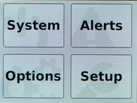
About using the LCD
To manage the platform using the LCD menu options, tap the touchscreen LCD to
put it into menu mode. The LCD is operational even when the Host is powered
off, provided that Always-On Management and the LCD are fully booted.
It might take a few minutes
for the LCD to become operational when the system is started from a powered off
state.
When using the
LCD to configure the unit, be sure to use the
Commit
option to save all settings.Reboot the unit
You can use the
touchscreen LCD to perform a soft reboot of the unit.
- Touch the screen to activate the LCD menus.
- TapSystem.The System screen displays.
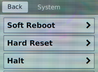
- On the System screen, tapSoft Reboot.
- TapConfirmto reboot the unit.
Reset the unit
You can use the
touchscreen LCD to perform a hard reset of the unit.
- Touch the screen to activate the LCD menus.
- TapSystem.The System screen displays.
- On the System screen, tapHard Reset.
- TapConfirmto reset the unit.
Halt the unit
You can use the touchscreen LCD
to halt the unit.
- Touch the screen to activate the LCD menus.
- TapSystem.The System screen displays.
- On the System screen, tapHalt.
- TapConfirmto halt the unit.
Power off/on the unit
You can use the touchscreen LCD to power
the unit off and on.
- Touch the screen to activate the LCD menus.
- TapSystem.The System screen displays.
- On the System screen, swipe up to scroll down and tapPower OfforPower On.
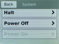
- TapConfirmto power off/on the unit.
Clear alerts
You can use the touchscreen LCD
to clear alerts from the LCD.
- Touch the screen to activate the LCD menus.
- TapAlerts.The Alerts screen displays.
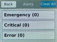
- On the Alerts screen, clear either all alerts or alerts of a specific priority:
- To clear all alerts, tapClear All.
- To clear only alerts of only a specific priority, tap the priority name to view alerts with that priority, and then tapClear.
Configure LCD brightness
You can use the touchscreen LCD
to adjust the brightness of the display.
- Touch the screen to activate the LCD menus.
- TapOptions.The Options screen displays.
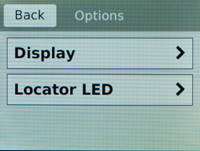
- TapDisplay.The Brightness screen displays.

- Use the left and right arrows to adjust the brightness of the LCD in real-time.
- ClickBackto return to the previous screen.
Enable/Disable the chassis locator
LED
You can use the touchscreen LCD to enable
and disable the chassis locater LED.
- Touch the screen to activate the LCD menus.
- TapOptions.The Options screen displays.
- ClickLocator LED.The Locator LED screen displays.
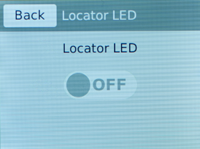
- Tap to enable or disable the chassis locator LED.
About platform LEDs
The behavior of the various LEDs on the platform indicate the status of the
system or component.
Status LED
The status LED indicates the operating state of the system.
State |
Description |
|---|---|
off/none |
System is powered down. |
green solid |
System is running in normal mode. Also indicates that the
system is in an Active state of a device group. |
amber solid |
System is running in an impaired mode or is operating in
one of these conditions:
|
amber blinking |
System might be in a state in which a software or hardware
problem is interfering with control of the LCD or
communication is lost between the system and the LCD. |
Alarm LED
The alarm LED indicates system alarm conditions and the severity of the
alarm condition.
There
are five levels of messages.
The alarm LED remains lit until you have used the
LCD panel to clear alerts above an informational level.
State |
Description |
|---|---|
off/none |
Informational or no alarm conditions are present. System is operating properly. |
amber solid |
Warning (0). System may not be operating properly, but the
condition is not severe or potentially damaging. |
amber blinking |
Error (1). System is not operating properly, but the
condition is not severe or potentially damaging. |
red solid |
Alert (2) or Critical (3). System is not operating
properly, and the condition is potentially damaging. |
red blinking |
Emergency (4). System is not operating, and the condition
is potentially damaging. |
Power 1 and Power 2 LEDs
The Power 1 and Power 2 LEDs on the front of the chassis indicate the
general operating state of the power supply units (PSUs).
Power supply unit (PSU)
state |
Description |
|---|---|
green solid |
PSU is present and operating
properly. Also indicates when the system is in power standby
mode. |
amber solid |
PSU is present, but not operating
properly. |
off/none |
No PSU is present. |
AC power supply unit (PSU) LEDs
The LEDs located on the AC power supply units (PSUs) indicate the operating state of
the PSUs.
Input LED |
Output LED |
Condition |
|---|---|---|
green solid |
green solid |
Normal operation |
off |
off |
Fault: Input UV, Input OV, VSB SC |
off |
amber solid |
Not valid |
green solid |
amber solid |
Warning: VSB
OC Fault: Fan, OTP, OC, VOUT OV/UV |
green solid |
amber blinking |
Warning: FAN, OTP, OC, VOUT OV/UV |
green blinking |
amber solid |
Fault: Input OV |
green blinking |
amber blinking |
Warning: Input OV, Input UV |
green blinking |
off |
Not valid |
green solid |
green blinking |
PS_ON_L is high |
green solid |
off |
PS_KILL PSU not inserted |
OV - Over Voltage; OTP - Over Temperature Protection; UV - Under Voltage;
OC - Over Current; VSB - Standby Voltage
DC power supply unit (PSU) LEDs
The LEDs located on the DC power supply units (PSUs) indicate the operating state of the
PSUs.
Input LED |
Output/Fault LED |
Condition (PWR-0307-01) |
Condition (PWR-0307-02 and
later) |
Condition (PWR-0378-xx) |
|---|---|---|---|---|
green solid |
green solid |
Normal operation |
Normal operation |
Normal operation |
off |
off |
Fault: Input UV |
Fault: Input UV, VSB SC |
Fault: Input UV |
off |
amber solid |
Fault: Input OV |
Not valid |
Not valid |
green solid |
amber solid |
Warning: VSB
OC Fault: Fan, OTP, OC, VOUT OV/UV |
Warning: VSB
OC Fault: Fan, OTP, OC, VOUT OV/UV |
Warning: VSB
OC Fault: Fan, OTP, OC, VOUT OV/UV |
green solid |
amber blinking |
Warning: FAN, OTP, OC, VOUT
OV/UV |
Warning: FAN, OTP, OC, VOUT
OV/UV |
Warning: FAN, OTP, OC, VOUT OV/UV |
green blinking |
amber solid |
Not valid |
Fault: Input OV |
Fault: Input OV |
green blinking |
amber blinking |
Not valid |
Warning: Input OV, Input
UV |
Warning: Input OV, Input UV |
green blinking |
off |
Fault/Warning: Input OV |
Not valid |
Not valid |
green solid |
green blinking |
PS_ON_L is high |
PS_ON_L is high |
PS_ON is high |
green solid |
off |
Fault: VSB SC, PS_KILL PSU not
inserted |
PS_KILL PSU not inserted |
PS_KILL PSU not inserted |
OV - Over Voltage; OTP - Over Temperature Protection; UV - Under Voltage;
OC - Over Current; VSB - Standby Voltage
Define custom alerts
Two files on the system define
alerts that could cause the LED behavior to change:
- The/etc/alertd/alert.conffile defines standard system alerts. Do not edit this file.
- The/config/user_alert.conffile defines custom settings. You should edit only this file.
- Open a command prompt on the system.
- Change to the/configdirectory.cd /config
- Using a text editor, such as vi or Pico, open the/config/user_alert.conffile.
- Edit the file, as needed.For example, add these lines to the end of the file to create a custom alert in which the front panel LEDs indicate when a node is down:alert BIGIP_MCPD_MCPDERR_POOL_MEMBER_MON_DOWN "Pool member (.*?):(.*?) monitor status down." { snmptrap OID=".1.3.6.1.4.1.3375.2.4.0.10"; lcdwarn description="Node down" priority="1" } alert BIGIP_MCPD_MCPDERR_NODE_ADDRESS_MON_DOWN "Node (.*?) monitor status down." { snmptrap OID=".1.3.6.1.4.1.3375.2.4.0.12"; lcdwarn description="Node address down" priority="1" } alert BIGIP_MCPD_MCPDERR_POOL_MEMBER_MON_UP "Pool member (.*?):(.*?) monitor status up." { snmptrap OID=".1.3.6.1.4.1.3375.2.4.0.11" } alert BIGIP_MCPD_MCPDERR_NODE_ADDRESS_MON_UP "Node (.*?) monitor status up." { snmptrap OID=".1.3.6.1.4.1.3375.2.4.0.13" }
- Save the file and exit the text editor.
About platform interfaces
Every platform includes multiple interfaces. The exact number of interfaces that are on the system depends on the platform type.
Each interface on the platform has a set of properties that you can configure, such as enabling or disabling the interface, setting the requested media type and duplex mode, and configuring Ethernet flow control.
Use only IEC/EN 60825-1 Class I SFP modules, and for safety ensure not to look directly into fiber cable ends.
About 10GbE SFP+
interfaces
The i5000/i7000/i10000/i11000 Series platforms include 10 GbE (SFP+) ports
(1.1-1.4 and 2.1-2.4), in which you can use 10 GbE (SFP+) or 1GbE (SFP)
transceiver modules.
About 40GbE QSFP+
interfaces
On platforms that include 40GbE interface ports, you can use the ports as a
single 40GbE port or as four 10GbE SFP+ ports.
Each 40GbE port supports four bicolor green/amber LEDs to indicate the
combined link and activity status of each port while operating in both native
40GbE modes (bundled), in addition to in 4 x 10GbE breakout mode (unbundled).
When operating in a native 40GbE mode, all four LEDs operate in unison per
port to indicate the combined link and activity status for a given port. When
operating in a 4 x 10GbE breakout mode, all four LEDs are used independently
to indicate the combined link and activity status for each 10GbE breakout
port.
The
40GbE ports (i5000/i7000 Series: 3.0-6.0 and i10000/i11000 Series: 3.0-8.0)
default to 40GbE.
The cable that you
use when operating at 40GbE is an industry-standard OM3 qualified multi-mode
fiber optic cable with female MPO/MTP connectors at both ends. You must
provide your own cable for 40GbE operation.You can also disable the 40GbE bundle and use them as individual 10GbE ports
using a QSFP+ breakout cable. This cable has a female MPO/MTP connector at one
end, which connects to the QSFP+ port, and four LC duplex connectors at the
other end, which connect to SFP+ modules on an upstream switch.
If you are using a breakout cable for 10GbE
connectivity, you should use the supported distance as detailed in the
Specifications for fiber QSFP+ modules
section and not the Specifications for fiber SFP+
modules
section of the F5 Platforms:
Accessories
guide at techdocs.f5.com/en-us/hw-platforms/f5-plat-accessories.html
.You can order these QSFP+ components from F5:
- QSFP+ breakout cables (MTP to LC), provided as a pair, in these lengths:
- 1 meter (F5-UPG-QSFP+-1M-2)
- 3 meter (F5-UPG-QSFP+-3M-2+)
- 10 meter (F5-UPG-QSFP+-10M-2)
- F5-branded 40GbE QSFP+ transceiver modules (F5-UPG-QSFP+)
Configure bundling for 40GbE QSFP+
interfaces using tmsh
You can use
tmsh
to configure bundling for the 40GbE
QSFP+ interfaces on a platform. When you disable bundling, you can use the
40GbE ports as individual 10GbE ports.- Open the TMOS Shell (tmsh).tmsh
- Change to the network module.netThe system prompt updates with the module name:user@bigip01(Active)(/Common)(tmos.net)#
- Configure bundling for a specific interface.modify interface <interface-key> bundle [ enabled | disabled ]
About 100GbE interfaces
On platforms that include 100GbE interface ports, you can
use only F5-branded 100GbE QSFP28 transceiver modules in those ports.
On
the i10010 platform, the 100GbE ports
(1.0-4.0)
default to 100GbE. The cable that you use when operating at 100GbE with
100GBASE-SR4 transceiver modules is an industry-standard OM4 qualified
multi-mode fiber optic cable with female MPO/MTP connectors at both ends. The
cable that you use with 100GBASE-LR4 transceiver modules is an
industry-standard SMF fiber optic cable with LC duplex connectors and a reach
of up to 10km. You must provide your own cable and F5-branded QSFP28
transceiver modules for 100GbE operation.If you are using a breakout cable for 10GbE
connectivity, you should use the supported distance as detailed in the
Specifications for fiber QSFP+ modules
section and not the Specifications for fiber SFP+
modules
section of the F5 Platforms:
Accessories
guide at techdocs.f5.com/en-us/hw-platforms/f5-plat-accessories.html
.Configure bundling for 100GbE interfaces using
tmsh
You can use
tmsh
to configure bundling
for the 100GbE QSFP28 interfaces on the platform at either 100GbE or 40GbE speeds.
The i10010 platform
does not support breaking out the 100GbE interfaces (that is, disabling
bundling).
- Open the TMOS Shell (tmsh).tmsh
- Change to the network module.netThe system prompt updates with the module name:user@bigip01(Active)(/Common)(tmos.net)#
- Configure bundling for a specific interface using this syntax.modify interface <interface-key>bundle[enabled|disabled]bundle-speed[100G|40G|not-supported]The default value ofbundle-speedis determined by the interface type. Unbundled interfaces havebundle-speedset tonot-supported.
Configure FEC for 100GbE interfaces using tmsh
If your upstream switch does not
support Reed-Solomon Forward Error Correction (RS-FEC), you can use
tmsh
to disable it for the
100GbE interfaces on your platform. RS-FEC is intended to be enabled with 100GBASE-SR links and disabled for
100GBASE-LR4 links.
- Open the TMOS Shell (tmsh).tmsh
- Change to the network module.netThe system prompt updates with the module name:user@bigip01(Active)(/Common)(tmos.net)#
- Configure FEC for a specific interface using this syntax.modify interface <interface-key>forward-error-correction[enabled|disabled]
About managing interfaces
You can use the TMOS Shell (
tmsh
) or the Configuration utility to manage platform interfaces.View the status of a specific
interface using tmsh
You can use
tmsh
to view the status of a specific
interface on a platform.- Open the TMOS Shell (tmsh).tmsh
- Change to the network module.netThe system prompt updates with the module name:user@bigip01(Active)(/Common)(tmos.net)#
- Display the current status of a specific interface.show interface <interface-key>This is an example of the output that you might see when you run this command on a specific interface:---------------------------------------------------------------- Net::Interface Name Status Bits Bits Pkts Pkts Drops Errs Media In Out In Out ---------------------------------------------------------------- 3.0 up 805.1G 0 1.2G 0 1.2G 0 40000SR4-FD
View the status of all interfaces
using tmsh
You can use
tmsh
to view the status of all interfaces
on the platform.- Open the TMOS Shell (tmsh).tmsh
- Change to the network module.netThe system prompt updates with the module name:user@bigip01(Active)(/Common)(tmos.net)#
- Display the current status of all interfaces.show interfaceThis is an example of the output that you might see when you run this command.------------------------------------------------------------------- Net::Interface Name Status Bits Bits Pkts Pkts Drops Errs Media In Out In Out ------------------------------------------------------------------- 1.0 uninit 0 0 0 0 0 0 none 1.1 miss 0 0 0 0 0 0 none 1.2 miss 0 0 0 0 0 0 none 1.3 miss 0 0 0 0 0 0 none 1.4 miss 0 0 0 0 0 0 none 2.0 uninit 0 0 0 0 0 0 none 2.1 miss 0 0 0 0 0 0 none 2.2 miss 0 0 0 0 0 0 none 2.3 miss 0 0 0 0 0 0 none 2.4 miss 0 0 0 0 0 0 none 3.0 up 805.0G 0 1.2G 0 1.2G 0 40000SR4-FD 3.1 uninit 0 0 0 0 0 0 none 3.2 uninit 0 0 0 0 0 0 none 3.3 uninit 0 0 0 0 0 0 none 3.4 uninit 0 0 0 0 0 0 none 4.0 miss 0 0 0 0 0 0 none 4.1 uninit 0 0 0 0 0 0 none 4.2 uninit 0 0 0 0 0 0 none 4.3 uninit 0 0 0 0 0 0 none 4.4 uninit 0 0 0 0 0 0 none 5.0 miss 0 0 0 0 0 0 none 5.1 uninit 0 0 0 0 0 0 none 5.2 uninit 0 0 0 0 0 0 none 5.3 uninit 0 0 0 0 0 0 none 5.4 uninit 0 0 0 0 0 0 none 6.0 miss 0 0 0 0 0 0 none 6.1 uninit 0 0 0 0 0 0 none 6.2 uninit 0 0 0 0 0 0 none 6.3 uninit 0 0 0 0 0 0 none 6.4 uninit 0 0 0 0 0 0 none 7.0 miss 0 0 0 0 0 0 none 7.1 uninit 0 0 0 0 0 0 none 7.2 uninit 0 0 0 0 0 0 none 7.3 uninit 0 0 0 0 0 0 none 7.4 uninit 0 0 0 0 0 0 none 8.0 miss 0 0 0 0 0 0 none 8.1 uninit 0 0 0 0 0 0 none 8.2 uninit 0 0 0 0 0 0 none 8.3 uninit 0 0 0 0 0 0 none 8.4 uninit 0 0 0 0 0 0 none mgmt up 17.1G 19.0M 26.7M 31.0K 0 0 1000T-FD
View the status of all interfaces
using the Configuration utility
You can use the
Configuration utility to view the status of all interfaces on the platform.
- On the Main tab, click .This displays the list of available interfaces.
- On the menu bar, clickStatistics.The Statistics screen for all interfaces opens.
About
interface media type and duplex mode
All interfaces on the system default to auto-negotiate speed
and full duplex settings. We recommend that you also configure any network
equipment that you plan to use with the system to auto-negotiate speed and
duplex settings. If you connect the system to network devices with forced
speed and duplex settings, you must force the speed and duplex settings of the
system to match the settings of the other network device.
If the system is attempting to
auto-negotiate interface settings with an interface that has the speed and
duplex settings forced (that is, auto-negotiation is disabled), you will
experience severe performance degradation.
By default, the media type on interfaces is set to
automatically detect speed and duplex settings, but you can specify a media
type as well. Use this syntax to set the media type:
tmsh modify net interface <interface-key> media <media-type> | auto
If the media type does not accept the duplex mode setting, a
message appears. If media type is set to
auto
, or if the interface
does not accept the duplex mode setting, the duplex setting is not saved to
the /config/bigip_base.conf
file.Auto-MDI/MDIX functionality is retained when you
manually configure an interface to use specific speed and duplex settings. You
can use either a straight-through cable or a crossover cable when media
settings are forced, and you will be able to successfully link to either DTE
or DCE devices.
View valid media types for an
interface
You can use
tmsh
to view the valid media types for an
interface.
This platform might not support all of the media
type options that are available in
tmsh
.- Open the TMOS Shell (tmsh).tmsh
- Change to the network module.netThe system prompt updates with the module name:user@bigip01(Active)(/Common)(tmos.net)#
- Display the valid media types for a specific interface.list interface <interface-key> media-capabilitiesIn all Gigabit Ethernet modes, the only valid duplex mode is full duplex.This is an example of the output that you might see when you run this command on a specific interface:net interface 2.0 { media-capabilities-sfp { none auto 40000SR4-FD 40000LR4-FD } }
Valid media types
This table lists the valid media types for the
tmsh
interface
command.This platform might not support
all of the media type options that are available in the TMOS Shell (
tmsh
).10baseT half |
1000baseLX full |
10baseT full |
1000baseCX full |
10GbaseER full |
1000baseT half |
10GbaseLR full |
1000baseT full |
10GbaseSR full |
1000baseSX full |
10GbaseT full |
100GbaseSR4 full |
10SFP+Cu full |
100GbaseLR4 full |
40GbaseSR4 full |
auto |
40GbaseLR4 full |
none |
100baseTX half |
no-phy |
100baseTX full |
About network interface LED behavior
The appearance and behavior of the network interface LEDs on the platform
indicate network traffic activity, interface speed, and interface duplexity.
SFP/SFP+ port LED behavior
The appearance and behavior of the SFP/SFP+ port LEDs indicate network traffic
activity, interface speed, and interface duplexity.
State |
Description |
|---|---|
off (not lit) |
No link. |
amber solid |
Linked at 1/10GbE. |
amber blinking |
Link is actively transmitting or receiving data at 1/10GbE. |
SFP+ port 40GbE bundled LED
behavior
The appearance and behavior of the SFP+ port 40GbE bundled LEDs indicate
network traffic activity, interface speed, and interface duplexity. When bundled,
all four LEDs blink in unison.
State |
Description |
|---|---|
off (not lit) |
No link. |
amber solid |
Linked at 40GbE. |
amber blinking |
Link is actively transmitting or receiving data at
40GbE. |
QSFP+ port LED behavior
The appearance and behavior of the QSFP+ port LEDs indicate network traffic
activity, interface speed, and interface duplexity.
State |
Description |
|---|---|
off (not lit) |
No link. |
green solid |
Linked at 40GbE when operating as a single 40GbE port (with
all four LEDs operating in unison). |
green blinking |
Link is actively transmitting or receiving data at 40GbE
(with all four LEDs operating in unison). |
amber solid |
Linked at 10GbE when operating as four 10GbE ports. |
amber blinking |
Link is actively transmitting or receiving data at 10GbE. |
QSFP28 port LED behavior
The appearance and behavior of the QSFP28 port LEDs indicate network traffic
activity, interface speed, and interface duplexity.
State |
Module |
Description |
|---|---|---|
off (not lit) |
QSFP+ or QSFP28 |
No link. |
blue solid |
QSFP28 |
Linked at 100GbE (with all four LEDs operating in
unison). |
blue blinking |
QSFP28 |
Link is actively transmitting or receiving data at 100GbE
(with all four LEDs operating in unison). |
green solid |
QSFP+ |
Linked at 40GbE when operating as a single 40GbE port (with
all four LEDs operating in unison). |
green blinking |
QSFP+ |
Link is actively transmitting or receiving data at 40GbE
(with all four LEDs operating in unison). |
amber solid |
QSFP+ |
Linked at 10GbE when operating as four 10 GbE
ports. |
amber blinking |
QSFP+ |
Link is actively transmitting or receiving data at
10GbE. |
About Always-On Management (AOM)
The Always-On Management (AOM) subsystem enables you to manage the system
remotely using the serial console or SSH, even if the host is powered down.
The AOM Command Menu operates independently of the
Traffic Management Operating System
(TMOS
).You can use the command menu to reset the unit if TMOS has locked up or get
access to TMOS directly, so that you can configure it from the command-line
interface.
Access the AOM Command Menu from
the serial console
You can access the AOM
Command Menu after connecting to the front panel serial console.
- Connect to the system using the serial console.
- Open the AOM Command Menu.Esc (
Create an
AOM admin user account
If you would like to access AOM over the
network rather than using the serial console, you need to create an AOM admin
user account.
This account is created on the AOM subsystem only
and is not saved to your BIG-IP
system configuration.
- Connect to the system using the serial console.
- Create an admin user account:
- On a newly configured BIG-IP system, typeaom_setup_user.
- On a previously configured BIG-IP system, typeaom_setup_user -oto override the existing AOM admin user account.
- Type the username you want.
- Type the required password.
- Type the new password again to confirm it.When the account creation is successful, a message similar to this one displays:AOM username aom-admin successfully set and enabled. Note that the AOM network must be configured via the AOM menu.
- Verify that the AOM admin user account is enabled and set up correctly.aom_setup_user -lA message similar to this one displays:Current AOM username: aom-admin (enabled)
Configure the AOM management
network
You can assign a management IP address, netmask, and gateway to access
AOM either manually or with DHCP.
- Connect to the system using the serial console.
- Open the AOM Command Menu.Esc (
- Typento open the AOM management network configurator.
- Assign a management IP address, netmask, and gateway:
- To use DHCP to assign the addresses, typeywhen prompted about using DHCP.
- To manually assign the addresses, typenwhen prompted about using DHCP. At the prompts, type values for IP address (required), netmask (required), and gateway (optional).
A confirmation message displays the configured management IP address, netmask, and gateway. - Typeito verify the assigned addresses.


