Updated Date: 06/30/2026
System Settings
You can access system settings in the system controller webUI and chassis partition webUI. Each webUI provides different settings.
This table lists the available system settings in the system controller and chassis partition webUIs:
| System controller webUI | Chassis partition webUI |
|---|---|
| Configuration Backup | Configuration Backup |
| Controller Management | General |
| DNS | High Availability |
| General | Licensing |
| Licensing | System Security |
| Management Interfaces | |
| Management VLANs | |
| System Security | |
| Time Settings |
You can back up the configurations of the system controller or chassis partition in which you are working from the webUI.
-
Log in to the VELOS system controller webUI or the chassis partition webUI using an account with admin access.
-
On the left, click System Settings > Configuration Backup.
-
Click Create.
The Create Configuration Backup screen displays.
-
In the Name field, enter a name for the backup (for example, system-12-21-21).
-
Click Create.
The backup is created and added to the list.
-
-
To delete a backup file, select the file and click Delete.
System controller and chassis partition configuration backups are stored in configs/. Backups should be stored off the system.
You can restore configurations from the CLI. For more information on saving and restoring the configuration, see the Complete backup and restore overview section.
You can configure system controller high availability (HA) from Controller Management screen on the system controller webUI. The system controllers work together as a redundant pair. The default mode for system controller HA is Auto, which automatically selects the system controller that is best suited at the time as the active controller and fails over only as needed.
The High Availability screen on the chassis partition webUI includes options for configuring chassis partition HA. High availability is already implemented for chassis partitions on the VELOS system.
You should not need to change system controller high availability (HA) to something other than the default configuration (Auto), but you can opt to change the configuration or initiate a failover from the active controller to the standby from the system controller webUI.
-
Log in to the VELOS system controller webUI using an account with admin access.
-
On the left, click System Settings > Controller Management.
-
From the Preferred Node drop down, select System Controller 1 or System Controller 2 to act as an active system controller, or choose Auto (recommended). Click Update, to change the settings.
Note: Changing the Preferred Node configuration creates a failover event and ends the session if you select the system controller that is currently acting as the standby. Wait 30 seconds and then start a new session with either the floating IP address or the active system controller IP address after the change has completed.
Hardware health conditions of the system controllers always take precedence. If one of the system controllers is not healthy, the chassis partition will ignore the preference and synchronize with the healthy system controller.
-
To force a failover to occur immediately, click Failover.
Note: The Failover button is available only when Preferred Node field is set to Auto.
You would do this only if you want the current standby system controller to become the active system controller.
You can change the preferred system controller high availability (HA) mode from either the system controller or chassis partition CLI.
-
Connect using SSH to the system controller floating management IP address or chassis partition management IP address.
-
Log in to the command line interface (CLI) of the system controller or chassis partition using an account with admin access.
When you log in to the system, you are in user (operational) mode.
-
Change to config mode.
configThe CLI prompt changes to include
(config). -
Change system controller high availability/redundancy to a specified mode.
system redundancy config mode [ auto | prefer-1 | prefer-2 }These redundancy modes are available:
Option Description auto System chooses preferred mode automatically. This is the default value. prefer-1 Prefer controller-1 to be active. prefer-2 Prefer controller-2 to be active. This example shows configuring controller-1 as the preferred active system controller from the system controller CLI:
syscon-1-active(config)# system redundancy config mode prefer-1 -
Commit the configuration changes.
commit
You can view or change the configuration of management interfaces, prefix length (netmask), and gateway for the VELOS system at the chassis level.
-
Log in to the VELOS system controller webUI using an account with admin access.
-
On the left, click System Settings > Management Interfaces.
-
On the left of Management IP Address area, click edit icon.
-
For DHCP, select Enabled if the management port is getting addresses from a DHCP server or select Disabled to configure the addresses manually.
-
From Address, select whether to configure only IPv4 addresses, only IPv6 addresses, or both IPv4 and IPv6 addresses.
-
Configure IPv4 addresses:
- For System Controller 1, System Controller 2, and Floating, enter IP addresses in IPv4 format.
- For Prefix Length, enter a number from 1-32 for the length of the prefix.
- For Gateway, type the gateway IP address.
-
Configure IPv6 addresses:
- For System Controller 1, System Controller 2, and Floating, enter IP addresses in IPv6 format.
- For Prefix Length, enter a number from 10-127 for the length of the prefix.
- For Gateway, type the gateway IP address.
-
Click Save.
-
-
On the left of Link Aggregation area, click edit icon.
-
select Enabled to enable aggregation for the management ports between the system controllers and an upstream switch.
Enabling link aggregation increases the bandwidth between peers by load balancing traffic across both ports.
-
From Type, select a link aggregation type:
Type Description STATIC Use static link aggregation, where you manually configure links and link state is not updated dynamically. LACP Use Link Aggregation Control Protocol (LACP) to allow for automatic bundling of links. -
From Interval, select FAST (every second) or SLOW (every 30 seconds).
-
From Mode, select an aggregration mode.
Type Description ACTIVE Send link aggregation control protocol data unit (LACPDU) packets unconditionally. PASSIVE Send LACPDU packets only when an LACP device is detected. -
For Name, you can change the name from the default value (mgmt-aggr) when link aggregation is enabled.
-
The Configured Members area displays interfaces configured with link aggregation.
-
Click Save.
-
Forwarding is enabled for both management ports when link aggregation is used. If one port of the aggregation goes down, traffic is seamlessly handled by the remaining management port. A health-driven HA switchover need not occur to activate the alternate management port as it does when the management ports are operating independently.
There is also a gain in overall management port throughput. Specifically, total management port bandwidth doubles to 20 Gbps when aggregated. When not aggregated, only one management link is active at a time, and total bandwidth is limited to 10 Gbps.
The downside of using management port aggregation is that the ports to which the management ports connect must also be aggregated.
There is no difference in IP configuration between aggregated and independent modes of operation. That is because aggregation (an L2 feature) is applied to the physical switch ports that physically connect to the management network, and IP addresses are applied to host interfaces at L3 connecting to entirely different physical switch ports.
You can configure the custom static routes on the management network to direct management traffic based on destination IPs or networks using the CLI.
After you configure a individual management IP addresses for both system controllers. You can configure the custom static routes from the CLI.
-
Connect to the system using a management console or console server.
The default baud rate and serial port configuration is 19200/8-N-1.
-
Log in to the command line interface (CLI) of the system controller using an account with admin access.
When you log in to the system, you are in user (operational) mode.
-
Change to config mode.
configThe CLI prompt changes to include
(config). -
Configure the custom static route:
system routes route <network> config gateway <ip-address> description <route-description>In this example, a gateway IPv4 for Route-1 is configured:
syscon-1-active(config)# system routes route 10.172.0.0/16 config gateway 10.144.191.44 description Route-1In this example, a gateway IPv6 for Valid IPv6 route is configured:
syscon-1-active(config)# system routes route 2001:db8:abcd:12::/64 config gateway 2620:128:e008:4031::30 description "Valid IPv6 route" -
Commit the configuration changes.
commit -
Return to user (operational) mode.
end -
Display the configured custom route:
show system routes route <network>A summary to this example displays:
syscon-1-active# show system routes route 10.172.0.0/16
NETWORK        GATEWAY        DESCRIPTION
-------------------------------------------
10.172.0.0/16  10.144.191.44  Route 1
You can view the configured custom static routes from the CLI.
-
Connect to the system using a management console or console server.
The default baud rate and serial port configuration is 19200/8-N-1.
-
Log in to the command line interface (CLI) of the system controller using an account with admin access.
When you log in to the system, you are in user (operational) mode.
-
Display the configured custom route:
show system routesA summary to this example displays:
syscon-1-active# show system routes
NETWORK        GATEWAY        DESCRIPTION
-------------------------------------------
10.20.40.0/24  10.144.191.10  Route 2
10.20.50.0/24  10.144.191.10  Route 2
10.172.0.0/16  10.144.191.44  Route-1
You can configure the custom static routes on the partition from the system controller CLI.
-
Connect to the system using a management console or console server.
The default baud rate and serial port configuration is 19200/8-N-1.
-
Log in to the command line interface (CLI) of the system controller using an account with admin access.
When you log in to the system, you are in user (operational) mode.
-
Change to config mode.
configThe CLI prompt changes to include
(config). -
Configure the custom static route:
partitions partition <partition_name> routes route <network> config gateway <ip-address> description <route-description>In this example, a gateway IPv4 for Route-1 is configured:
syscon-1-active(config)# partitions partition p3 routes route 10.172.0.0/16 config gateway 10.144.191.44 description Route-1In this example, a gateway IPv6 for Valid IPv6 route is configured:
syscon-1-active(config)# partitions partition p3 routes route 2001:db8:abcd:12::/64 config gateway 2620:128:e008:4031::30 description "Valid IPv6 route" -
Commit the configuration changes.
commit -
Return to user (operational) mode.
end -
Display the configured custom route:
show partitions partition <partition_name> routesA summary to this example displays:
syscon-1-active# show partitions partition p3 routes
NETWORK        GATEWAY        DESCRIPTION
-------------------------------------------
10.172.0.0/16  10.144.191.44  Route-1
You can view the configured custom static routes from the CLI.
-
Connect using SSH to the chassis partition management IP address.
-
Log in to the command line interface (CLI) of the chassis partition using an account with admin access.
When you log in to the system, you are in user (operational) mode.
-
Display the configured custom route:
show system routesA summary to this example displays:
p3-1# show system routes
NETWORK        GATEWAY
------------------------------
10.20.40.0/24  10.144.191.10
10.20.50.0/24  10.144.191.10
You can delete files from the CLI.
-
Log in to the command line interface (CLI) of the system using an account with admin access.
When you log in to the system, you are in user (operational) mode.
-
Delete a configured custom route:
-
Delete specific route:
no system routes route <network>A summary to this example displays:
appliance-1(config)# no system routes route 10.20.30.0/24 -
Delete all configured routes:
no system routes route all
-
After you connect your system controllers to a management console or console server, you can configure a floating management IP address and individual management IP addresses for both system controllers from the system controller CLI. You can use either IPv4 or IPv6 format for these IP addresses.
-
Connect to the system using a management console or console server.
Note: The default baud rate and serial port configuration is 19200/8-N-1.
-
Log in to the command line interface (CLI) of the system controller using an account with admin access.
When you log in to the system, you are in user (operational) mode.
-
Change to config mode.
configThe CLI prompt changes to include
(config). -
Configure the management IP address for controller-1.
system mgmt-ip config [ipv4 | ipv6] controller-1 address <*ip-address*>This example assigns an IPv4 address:
syscon-1-active(config)# system mgmt-ip config ipv4 controller-1 address 192.0.2.10This example assigns an IPv6 address:
syscon-1-active(config)# system mgmt-ip config ipv6 controller-1 address 2001:db8:ffff:100::1 -
Configure the management IP address for controller-2.
system mgmt-ip config [ipv4 | ipv6] controller-2 address <*ip-address*>This example assigns an IPv4 address:
syscon-1-active(config)# system mgmt-ip config ipv4 controller-2 address 192.0.2.11This example assigns an IPv6 address:
syscon-1-active(config)# system mgmt-ip config ipv6 controller-2 address 2001:db8:ffff:101::1 -
Configure the floating IP address for the system controllers.
system mgmt-ip config [ipv4 | ipv6] floating <*ip-address*>This example assigns an IPv4 address:
syscon-1-active(config)# system mgmt-ip config ipv4 floating 192.0.2.15This example assigns an IPv6 address:
syscon-1-active(config)# system mgmt-ip config ipv6 floating 2001:db8:ffff:102::1 -
Configure the default gateway, if not using DHCP.
system mgmt-ip config [ipv4 | ipv6] gateway <*gateway-ip*>This example assigns an IPv4 gateway:
syscon-1-active(config)# system mgmt-ip ipv4 gateway 192.0.2.254This example assigns an IPv6 gateway:
syscon-1-active(config)# system mgmt-ip ipv6 gateway 2001:db8:ffff:100::fffe -
Configure the default CIDR prefix length.
system mgmt-ip config [ipv4 | ipv6] prefix-length <*prefix-length*>This example assigns a prefix length for an IPv4a address:
syscon-1-active(config)# system mgmt-ip ipv4 prefix-length 24This example assigns a prefix length for an IPv6 address:
syscon-1-active(config)# system mgmt-ip ipv6 prefix-length 64 -
Commit the configuration changes.
commit
The system saves the new IP addresses and gateway address for your system controllers. You can now use the floating IP address that you assigned to access the system either over SSH or using the webUI. The floating IP address will always be available on the primary system controller.
You can configure DNS for the VELOS system at the chassis level from the system controller webUI. This is used for name resolution such as when setting up the system.
-
Log in to the VELOS system controller webUI using an account with admin access.
-
On the left, click System Settings > DNS.
-
Under DNS Lookup Servers, specify the name servers that the system uses to validate DNS lookups, and resolve host names. For each name server you want to add:
-
On the left, click Add.
-
For IPv4 or IPv6 IP Address, enter the IP address of the name server that you want to add to the list.
-
Click Save.
To deletet the lookup servers, select the IP address from the Lookup Servers lists and click Delete.
-
-
Under DNS Search Domains, specify the domains that the system searches for local domain lookups and to resolve local host names. For each domain you want to add:
-
Click Add.
-
For Search Domain, enter the domain name of the name server that you want to add to the list. For example, DNSsearch.com
-
Click Save.
-
-
Under Host Entries, specify the local host name of the system. For each host system you want to add:
-
Click Add.
-
For HostName, enter the hostname of the host system.
-
For Alias, enter the alias name of the host system. Press enter to add additional values.
-
For IPv4 Address or IPv6 Address, enter the addresses of the host system. Press enter to add additional values.
-
Click Save.
-
DNS lookup servers and search domains are now specified for the VELOS system.
You can configure DNS for the VELOS system at the chassis level from the system controller CLI. This is used for name resolution such as when setting up the system.
-
Connect using SSH to the chassis partition management IP address.
-
Log in to the command line interface (CLI) of the chassis partition using an account with admin access.
When you log in to the system, you are in user (operational) mode.
-
Change to config mode.
configThe CLI prompt changes to include
(config). -
Configure a DNS lookup server.
system dns servers server <*ip-address*> port <*port*>This example configures a DNS server at 192.0.2.20:
syscon-1-active(config)# system dns servers server 192.0.2.20 port 53 -
Commit the configuration changes.
commit
A Management Virtual Local Area Network, also known as MGMT VLAN, is a designated Virtual Local Area Network (VLAN) used for the purpose of managing network devices, including switches, routers, firewalls, and other network equipment, providing secure and isolated access for admin users. This VLAN effectively segregates data traffic, thereby enhancing network security and stability. For example, with MGMT VLANs, you can:
- Separate tenants on different VLANs to enhance security and maintain distinct security zones within the same chassis. It helps users who prefer not to use a single shared VLAN for out-of-band management, as they see it as a potential risk where a compromised tenant could access other tenants.
- Manage IP addresses more effectively. You may not always have control over how IP addresses or VLANs are assigned. If IP addresses on the out-of-band network run out, additional ones might need to be requested. Sometimes, these new address blocks are not contiguous and are assigned to a different VLAN. In such cases, multiple VLANs must be brought into the chassis on the out-of-band network.
The MGMT VLAN enables VLAN tagging on the mgmt-interface on the system controllers. You can then assign system controllers, chassis partitions, and tenants to any of the tagged VLANs.
You can create an MGMT VLAN and then later associate the management interface with that MGMT VLAN from the system controller CLI.
-
Connect using SSH to the system controller management IP address.
-
Log in to the command line interface (CLI) of the system controller using an account with admin access.
When you log in to the system, you are in user (operational) mode.
-
Change to config mode.
configThe CLI prompt changes to include
(config). -
Create an MGMT VLAN.
mgmt-vlans mgmt-vlan <*\{ <vlan-id> \| range <range-of-vlan-ids> \}*> config name <*name*>This example creates an MGMT VLAN with an ID ‘11’:
syscon-1-active(config)# mgmt-vlans mgmt-vlan 11 config name mgmt-vlan-11 -
Commit the configuration changes.
commit
The MGMT VLAN is created and displayed in the MGMT VLAN list. You can use the MGMT VLANs when configuring interfaces, creating LAGs, and deploying tenants (one MGMT VLAN can be shared by more than one tenant within a chassis partition).
You can create a Management VLAN and then later associate the management interface with that Management VLAN from the system controller webUI.
-
Log in to the VELOS system controller webUI using an account with admin access.
-
On the left, click System Settings > Management VLANs.
-
Click Add to add the management VLANs.
-
In the Add Management VLAN section, enter management VLAN ID and name in the Management VLAN ID and Name fields respectively.
-
Click Save & Close.
To create another management VLAN ID without closing the current window, click Save & Create Another.
You can view all the MGMT VLANs created from the CLI.
-
Connect using SSH to the system controller management IP address.
-
Log in to the command line interface (CLI) of the system controller using an account with admin access.
When you log in to the system, you are in user (operational) mode.
-
Show configured MGMT VLANs.
show mgmt-vlansA summary similar to this example displays:
syscon-1-active# show mgmt-vlans
     MGMT      MGMT
     VLAN TAG  VLAN TAG  NAME
     ----------------------------------
     untagged  untagged  mgmt-untagged
     11        11        mgmt-vlan-11
     12        12        mgmt-vlan-12
     13        13        mgmt-vlan-13
You can delete MGMT VLANs created from the CLI.
-
Connect using SSH to the system controller management IP address.
-
Log in to the command line interface (CLI) of the system controller using an account with admin access.
When you log in to the system, you are in user (operational) mode.
-
Show configured MGMT VLANs.
show mgmt-vlansA summary similar to this example displays:
syscon-1-active# show mgmt-vlans MGMT MGMT VLAN TAG VLAN TAG NAME ---------------------------------- untagged untagged mgmt-untagged 11 11 mgmt-vlan-11 12 12 mgmt-vlan-12 13 13 mgmt-vlan-13 -
Delete an MGMT VLAN from the chassis controller.
no mgmt-vlans mgmt-vlan 13A summary similar to this example displays:
syscon-1-active(config)# no mgmt-vlans mgmt-vlan 13 -
Commit the configuration changes.
commit
To delete an Management VLAN from webUI, follow the below steps.
-
Log in to the VELOS system controller webUI using an account with admin access.
-
On the left, click System Settings > Management VLANs.
-
Select a management VLAN by selecting the checkbox.
-
Click Delete.
You can configure an MGMT VLAN to a system controller from the system controller CLI.
Note: F5 recommends configuring the MGMT VLAN from the console whenever possible. Changing the MGMT VLAN ID through the CLI will disconnect the management session. Additionally, you will need to reconfigure the upstream switch from untagged to tagged.
-
Connect using SSH to the system controller management IP address.
-
Log in to the command line interface (CLI) of the system controller using an account with admin access.
When you log in to the system, you are in user (operational) mode.
-
Change to config mode.
configThe CLI prompt changes to include
(config). -
Assign a controller management interface to an MGMT VLAN.
system mgmt-ip config mgmt-vlan``*<vlan-id>*This example shows assigning a controller management interface to an MGMT VLAN with an ID ‘11’:
syscon-1-active(config)# system mgmt-ip config mgmt-vlan 11 -
Commit the configuration changes.
commit
In case of downgrading to previous versions, delete the MGMT VLAN configuration before you start the downgrading. If not deleted, you will lose the management connectivity.
You can configure a Management VLAN to a system controller mgmt-ip from the system controller webUI.
Note: F5 recommends configuring the Management VLAN from the console whenever possible. Changing the Management VLAN ID through the webUI will disconnect the management session. Furthermore, you will need to reconfigure the upstream switch’s configuration from untagged to tagged.
-
Log in to the VELOS system controller webUI using an account with admin access.
-
On the left, click System Settings > Management VLANs.
-
In the Management VLAN section, select a management VLAN ID from the VLAN field dropdown.
-
Click Save.
You can view all the MGMT VLANs created from the CLI.
-
Connect using SSH to the system controller management IP address.
-
Log in to the command line interface (CLI) of the system controller using an account with admin access.
When you log in to the system, you are in user (operational) mode.
-
Show configured MGMT VLANs for system controller.
show running-config system mgmt-ipThis example shows the MGMT VLANs assigned to a system controller:
syscon-1-active# show running-config system mgmt-ip
You can untag an MGMT VLAN configuration assigned to a system controller from the system controller CLI.
-
Connect using SSH to the system controller management IP address.
-
Log in to the command line interface (CLI) of the system controller using an account with admin access.
When you log in to the system, you are in user (operational) mode.
-
Show the MGMT VLANs that are currently configured for the system controller to check the names of the MGMT VLANs.
show system mgmt-ip -
Change to config mode.
configThe CLI prompt changes to include
(config). -
Untag an MGMT VLAN configuration assigned to system controller.
no system mgmt-ip config mgmt-vlanThis example shows untagging an MGMT VLAN:
syscon-1-active(config)# no system mgmt-ip config mgmt-vlan -
Commit the configuration changes.
commit
You can configure an MGMT VLAN to a chassis partition from the CLI.
-
Connect using SSH to the system controller management IP address.
-
Log in to the command line interface (CLI) of the system controller using an account with admin access.
When you log in to the system, you are in user (operational) mode.
-
Change to config mode.
configThe CLI prompt changes to include
(config). -
Assign a partition management interface to an MGMT VLAN.
partitions partition``*<name>*config mgmt-ip mgmt-vlan*<vlan-id>*This example shows assigning a chassis partition management interface to an MGMT VLAN with an ID ‘12’:
syscon-1-active(config)# partitions partition default config mgmt-ip mgmt-vlan 12 -
Commit the configuration changes.
commit
Using the webUI, you can set up a Management VLAN for a specific chassis partition. It is possible to assign multiple VLANs to a single partition. However, only the VLANs that have been configured for that partition will be accessible for tenants to utilise.
-
Log in to the VELOS system controller webUI using an account with admin access.
-
On the left, click Chassis Partitions.
-
Select a partition by selecting the checkbox and then click Edit.
-
Select management VLANs from the list of available management VLANs by selecting the checkbox from the Management VLANs field and then click Save.
You can view MGMT VLAN to troubleshoot and check whether the correct MGMT VLANs are assigned to the chassis partition from the CLI.
-
Connect using SSH to the system controller management IP address.
-
Log in to the command line interface (CLI) of the system controller using an account with admin access.
When you log in to the system, you are in user (operational) mode.
-
Show configured MGMT VLANs for chassis partition.
show running-config partitions partition*<name>*This example shows the MGMT VLANs assigned to a chassis partition:
syscon-1-active# show running-config partitions partition default
You can untag an MGMT VLAN configuration assigned to a chassis partition from the CLI.
-
Connect using SSH to the system controller management IP address.
-
Log in to the command line interface (CLI) of the system controller using an account with admin access.
When you log in to the system, you are in user (operational) mode.
-
Show the MGMT VLANs that are currently configured for the chassis partition to check the names of the MGMT VLANs.
show running-config partitions partition*<name>* -
Change to config mode.
configThe CLI prompt changes to include
(config). -
Untag an MGMT VLAN configuration assigned to a partition.
no partitions partition``*<name>*config mgmt-ip mgmt-vlanThis example shows untagging an MGMT VLAN:
syscon-1-active(config)# no partitions partition default config mgmt-ip mgmt-vlan -
Commit the configuration changes.
commit
You can configure MGMT VLAN allow list for tenant on a chassis partition from the CLI.
-
Connect using SSH to the system controller management IP address.
-
Log in to the command line interface (CLI) of the system controller using an account with admin access.
When you log in to the system, you are in user (operational) mode.
-
Change to config mode.
configThe CLI prompt changes to include
(config). -
Create MGMT VLAN allow list for tenant on a chassis partition.
partitions partition``*<name>*config mgmt-vlans*\[ range of vlan-ids \]*This example shows the allowed list of MGMT VLANs for tenant on a chassis partition:
syscon-1-active(config)# partitions partition default config mgmt-vlans [ 11 12 ] -
Commit the configuration changes.
commit
You can view the list of allowed MGMT VLANs for a tenant on a chassis partition from the CLI.
-
Connect using SSH to the system controller management IP address.
-
Log in to the command line interface (CLI) of the system controller using an account with admin access.
When you log in to the system, you are in user (operational) mode.
-
Show the list of allowed MGMT VLANs for a tenant on a chassis partition.
show running-config partitions partition*<name>*This example shows the list of allowed MGMT VLANs for a tenant on a chassis partition:
syscon-1-active# show running-config partitions partition default
You can untag an MGMT VLAN configuration assigned to a chassis partition from the CLI.
-
Connect using SSH to the system controller management IP address.
-
Log in to the command line interface (CLI) of the system controller using an account with admin access.
When you log in to the system, you are in user (operational) mode.
-
Show the list of allowed MGMT VLANs for a tenant on a chassis partition
show running-config partitions partition*<name>* -
Change to config mode.
configThe CLI prompt changes to include
(config). -
Untag an MGMT VLAN configuration assigned to a partition.
no partitions partition``*<name>*config mgmt-vlanThis example shows untagging an MGMT VLAN:
syscon-1-active(config)# no partitions partition default config mgmt-vlan -
Commit the configuration changes.
commit
You can configure an MGMT VLAN to a chassis partition from the CLI.
-
Connect using SSH to the chassis partition management IP address.
-
Log in to the command line interface (CLI) of the chassis partition using an account with admin access.
When you log in to the system, you are in user (operational) mode.
-
Change to config mode.
configThe CLI prompt changes to include
(config). -
Assign an MGMT VLAN to a tenant.
tenants tenant``*<name>*config mgmt-ip mgmt-vlan*<vlan-id>*This example shows assigning an MGMT VLAN with an ID ‘12’ to a tenant:
default-1(config)# tenants tenant tenant1 config mgmt-ip mgmt-vlan 12 -
Commit the configuration changes.
commit
The configured tenant’s MGMT VLAN should be within the defined MGMT VLANs range for a specific partition.
You can configure a Management VLAN for a tenant from the webUI.
-
Log in to the VELOS chassis partition webUI using an account with admin access
-
On the left, click Tenant Management > Tenant Deployments.
-
Click on the tenant name to edit and configure the Management VLAN.
-
Select a management VLAN from the Management VLAN field dropdown and then click Save & Close.
You can view MGMT VLAN to troubleshoot and check whether the correct MGMT VLANs are assigned to the tenant from the CLI..
-
Connect using SSH to the chassis partition management IP address.
-
Log in to the command line interface (CLI) of the chassis partition using an account with admin access.
When you log in to the system, you are in user (operational) mode.
-
Show configured MGMT VLANs for tenant.
show running-config tenants tenant*<name>*This example shows the MGMT VLANs assigned to a tenant:
default-1# show running-config tenants tenant cbip2
You can untag an MGMT VLAN configuration assigned to a tenant from the CLI.
-
Connect using SSH to the chassis partition management IP address.
-
Log in to the command line interface (CLI) of the chassis partition using an account with admin access.
When you log in to the system, you are in user (operational) mode.
-
Show the MGMT VLANs that are currently configured in that chassis partition to check the names of the MGMT VLANs.
show tenants tenant*<name>* -
Change to config mode.
configThe CLI prompt changes to include
(config). -
Untag an MGMT VLAN configuration assigned to a tenant in a chassis partition.
no tenants tenant``*<name>*config mgmt-vlanThis example shows untagging an MGMT VLAN:
default-1(config)# no tenants tenant tenant1 config mgmt-vlan -
Commit the configuration changes.
commit
You can access settings for hardening the security of your system in the system controller or chassis partition webUI.
An allow list enables you to specify either specific IPv4 or IPv6 addresses, ports, or a netmask as an accepted source that can access the system.
When the IP address is configured and saved to the system allow list, only traffic coming from that IP address and port is accepted by the system’s management interface. You can also edit or delete entries in the allow list after you have configured them.
You can configure the system allow list from either the system controller or chassis partition webUI. To edit an existing allow list entry, select the IP address that you want to edit. You cannot change the designated name, but you can change all other fields.
-
Log in to the VELOS system controller webUI or the chassis partition webUI using an account with admin access.
-
On the left, click System Settings > System Security.
-
In the Allowed IP Addresses area, click Add to add an IP address to the allow list.
-
For Name, enter a descriptive name for the IP address.
-
For IPv4/IPv6, select IPv4 or IPv6.
-
For Address, enter the IP address to be added to the allow list.
-
For Prefix Length, enter or select the prefix length.
The prefix length values must be between 1 and 32 for IPv4 and between 1 and 128 for IPv6.
-
For Port, select a port number for the IP address.
Available options are:
- 443 (HTTPS): Allow only HTTP with SSL traffic on this IP address.
- 80 (HTTP): Allow only HTTP traffic on this IP address.
- 8888 (RESTCONF): Allow only RESTCONF traffic on this IP address.
- 161 (SNMP): Allow only SNMP traffic on this IP address.
- 7001 (VCONSOLE): Allow only VCONSOLE traffic on this IP address.
- 22 (SSH): Allow only SSH traffic on this IP address.
-
Click Save.
You can configure the system allow list from either the system controller or chassis partition CLI.
-
Log in to the command line interface (CLI) of the system controller or chassis partition using an account with admin access.
When you log in to the system, you are in user (operational) mode.
-
Change to config mode.
configThe CLI prompt changes to include
(config). -
Configure the system to allow traffic only from specified IP addresses.
Note: This is applicable only for ports 22, 161, 8888, 443, 80, and 7001.
system allowed-ips allowed-ip <*allowlist-profile-name*> config [ ipv4 | ipv6 ] address <*ip-address*> port <*port-number*>prefix-length <*subnet-prefix-length*>This example adds a specified IPv4 address to the system allow list:
syscon-1-active(config)# system allowed-ips allowed-ip test config ipv4 address
192.0.2.33 port 161 prefix-length 32
This example adds a netmask to the system allow list:
syscon-1-active(config)# system allowed-ips allowed-ip test config ipv4 address 12.13.14.0 port 161 prefix-length 24 -
Commit the configuration changes.
commit
You can run the system in appliance mode. Appliance mode adds a layer of security removing user access to Root and Bash. Enabling appliance mode disables all Root and Bash shell access for the system.
You can enable appliance mode at each of these levels:
- System
- Tenant
Appliance mode is disabled at all levels, by default. You can enable it from the webUI or the CLI. The appliance mode option for the system is available to users with admin access under System Settings > General in the webUI. For tenants, it is available in the webUI under Tenant Management > Tenant Deployments.
These are the effects of enabling appliance mode at each of the different levels.
System-level appliance mode
- Root or Bash access is disabled on the system.
- Console access: Root or Bash access is disabled on the system. Users can log in to the system CLI from the console using an admin account.
Tenant appliance mode
- Root access to the tenant is disabled by all means. Bash access is disabled for users (with a terminal shell flag enabled) inside the tenant.
- Users can access the tenant only through the webUI or the CLI.
- Tenant console access: Users can log in to the CLI from the virtual console using an admin account (with a terminal shell flag enabled).
You can enable appliance mode if you want to disable all root and Bash shell access.
Note: For greater security, it is highly recommended that you configure the system controllers and chassis partitions to run in appliance mode.
From the system controller webUI, appliance mode disables root and Bash access to the controllers. From the chassis partition webUI, appliance mode limits access to the specific chassis partition to which you are connected. You can enable or disable the appliance mode for system controllers and partitions from their respective webUIs.
Note: The appliance mode option for tenants is available in the chassis partition webUI under Tenant Management > Tenant Deployments.
-
Log in to the VELOS system controller webUI or the chassis partition webUI using an account with admin access.
-
On the left, click System Settings > System Security.
-
In the Shell Access section, click the edit icon to update the Appliance Mode field to Enabled or Disabled.
The default value is Disabled.
-
Click Save.
You can configure appliance mode from either the system controller or chassis partition CLI if you want to disable all root and Bash shell access.
Note: For greater security, it is highly recommended that you configure the system controllers and chassis partitions to run in appliance mode.
From the system controller CLI, appliance mode disables root and Bash access to the controllers. From the chassis partition CLI, appliance mode limits access to the specific chassis partition to which you are connected.
Note: The appliance mode option for tenants is available in the chassis partition CLI using the tenants tenant <*tenant-name*> config appliance-mode command sequence.
-
Connect using SSH to the system controller floating management IP address or chassis partition management IP address.
-
Log in to the command line interface (CLI) of the system controller or chassis partition using an account with admin access.
When you log in to the system, you are in user (operational) mode.
-
Change to config mode.
configThe CLI prompt changes to include
(config). -
Enable appliance mode.
system appliance-mode config [ disabled | enabled ]In this example, you enable appliance mode on the system controllers:
syscon-1-active(config)# system appliance-mode config enabled -
Commit the configuration changes.
commit
With appliance mode disabled, enabling the deny root SSH option will restrict the root user from accessing the system through SSH. However, root users can still be able to access the system using the console. This provides a maintenance window for system administrators without compromising on system security through SSH.
Note: All users excluding root users can access the system through SSH. If appliance mode is enabled, it overrides the deny root SSH option.
You can enable or disable root SSH from the webUI. Configuring deny root SSH to Enabled will disable the root SSH access but allows console root access.
-
Log in to the VELOS system controller webUI or the chassis partition webUI using an account with admin access.
-
On the left navigation pane, click System Settings > System Security.
-
Expand the Services card to view the configured values.
-
In the Shell Access section, click the edit icon to update the Deny Root SSH field to Enabled or Disabled.
The default value is Disabled.
-
Click Save.
You can configure deny root SSH mode from the CLI to disable the root SSH access. However, it allows console root access.
-
Connect using SSH to the system controller floating management IP address or chassis partition management IP address.
-
Log in to the command line interface (CLI) of the system controller or chassis partition using an account with admin access.
When you log in to the system, you are in user (operational) mode.
-
Change to config mode.
configThe CLI prompt changes to include
(config). -
Disable appliance mode.
system appliance-mode config [ disabled | enabled ]In this example, you disable appliance mode on the system controllers:
syscon-1-active(config)# system appliance-mode config disabled -
Enable deny root SSH mode.
system security deny-root-ssh config [ disabled | enabled ]In this example, you enable deny SSH mode on the system controllers:
syscon-1-active(config)# system security deny-root-ssh config enabled -
Commit the configuration changes.
commit
The LCD touchscreen enables you to view system status and manage the system without attaching a console or network cable. You can configure the LCD to meet security requirements by changing to a more restrictive operational mode.
The LCD touchscreen supports these modes:
- Standard
- Allows access to all options.
- Secure
- Allows access only to management and setup options only to secure sensitive system data. When you enable Secure mode, the system disables specific LCD UI features like system info, alarms, events log, reboot, reset, power off and shutdown. Management setup, LCD tests, power on, chassis locator, display brightness and controller console baud continue to function normally in Secure mode. The LCD UI grays out disabled options and makes them non-selectable. A padlock icon appears next to each disabled option to indicate that Secure mode is restricting access.
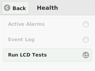
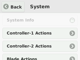
- Disabled
- Does not allow access to any options and displays only an image to indicate that the LCD touchscreen is disabled.

You can configure the operational mode of the touchscreen LCD from the webUI.
-
Log in to the webUI using an account with admin access.
-
On the left, click System Settings > System Security.
-
In the Shell & LCD Access card, click on the update button. For LCD mode select one of these options:
- Select Disabled to not allow access to any options; displays only an image to indicate that the LCD touchscreen is disabled.
- Select Secure to allow access only to management and setup options; displays a padlock icon next to limited options.
- Select Standard to allow access to all options.
-
Click Save
You can configure the operational mode of the touchscreen LCD from the CLI.
-
Connect using SSH to the system controller floating management IP address or chassis partition management IP address.
-
Log in to the command line interface (CLI) of the system controller or chassis partition using an account with admin access.
When you log in to the system, you are in user (operational) mode.
-
Change to config mode.
configThe CLI prompt changes to include
(config). -
Enable LCD operational mode.
components component lcd config mode [ standard | secure | disabled ]In this example, you enabled Standard LCD operational mode on the system:
syscon-1-active(config)# components component lcd config mode standard
Cryptographic agility on F5 VELOS systems enables you to replace cryptographic implementations for the httpd and sshd services. This applies to the F5OS management interface.
You can configure the SSL cipher suites used for the httpd service from the CLI.
-
Connect using SSH to the management IP address.
-
Log in to the command line interface (CLI) of the system using an account with admin access.
When you log in to the system, you are in user (operational) mode. Change to config mode:
-
Change to config mode.
configThe CLI prompt changes to include
(config). -
Enable the cryptographic protocol:
shell system security services service httpd config security-protocols [ Possible completions: TLSv1.2 TLSv1.3 ]In this example, you have enabled TLSv1.3 as security protocol:
shell syscon-1-active(config)# system security services service httpd config security-protocols [ Possible completions: TLSv1.2 TLSv1.3 ] syscon-1-active(config)# system security services service httpd config security-protocols [ TLSv1.3 ] -
Commit the configuration changes.
syscon-1-active(config-service-httpd)# commThe following warnings were generated:
shell system security services service httpd config security-protocols': Configuring HTTP SSL/TLS protocol will restart the HTTP service. Proceed? [yes,no] yes Commit complete.
After you commit the change, you are prompted to confirm the change. The service will then restart.
You can configure the cryptographic implementations on the system for the httpd and sshd services from the webUI.
-
Log in to the VELOS system controller webUI or the chassis partition webUI using an account with admin access.
-
On the left, click System Settings > System Security.
-
Expand the Services card to view the configured values. Click edit icon on the card, Services screen displays.
-
For httpd Cipher Suites, enter the SSL cipher suites used for the httpd service.
-
You can specify more than one cipher suite by separating the cipher suite names with a colon.
-
In the Cipher Suites text box, enter the desired SSL cipher suite in quotation marks. To disable a specific cipher suite, prefix its name with an exclamation point (!). In this example “ECDHE-RSA-AES256-GCM-SHA384:!ECDHE-ECDSA-AES256-GCM-SHA384” the cipher suite :!ECDHE-ECDSA-AES256-GCM-SHA384 is disabled.
Note:
- Configuring HTTP SSL/TLS cipher suite will restart the HTTP service.
- You can configure only the allowed SSL cipher suites. For further details, please refer to the section “Allowed SSL Cipher Suites for the httpd Service.”
-
-
For httpd Protocol, select the targeted protocol.
-
For sshd Ciphers, enter the ciphers to use for the sshd service.
For example, aes128-cbc or aes128-ctr. The cipher string can take several additional forms. It can consist of a single cipher suite or a list of cipher suites containing a certain algorithm, or cipher suites of a certain type. You can combine lists of cipher suites into a single cipher string by enclosing them in square brackets and delimiting them with a space.
-
For sshd KEX Algorithms, enter the key exchange algorithms used for the sshd service.
For example, diffie-hellman-group14-sha1 or diffie-hellman-group14-sha256. You can combine lists of KEX algorithms into a single string by enclosing them in square brackets and delimiting them with a space.
-
For sshd MAC Algorithms, enter the MAC algorithms used for the sshd service.
For example, hmac-sha2-512 or AEAD_AES_128_GCM. You can combine lists of MAC algorithms into a single string by enclosing them in square brackets and delimiting them with a space.
-
For sshd Host Key Algorithms, enter the host key algorithms used for the sshd service.
The following secure host key algorithms are supported when system is in non-FIPS mode and these are non-configurable:
S.No Host key algorithms 1 rsa-sha2-512 2 rsa-sha2-256 3 ecdsa-sha2-nistp256 4 ssh-ed25519 5 ssh-rsa Note: By default, the ssh-rsa host key algorithm is disabled. However, it can be enabled during system setup if necessary.
-
Click Save.
You can configure the sshd service from either the system controller or chassis partition CLI.
-
Connect using SSH to the system controller floating management IP address or chassis partition management IP address.
-
Log in to the command line interface (CLI) of the system controller or chassis partition using an account with admin access.
When you log in to the system, you are in user (operational) mode.
-
Change to config mode.
configThe CLI prompt changes to include
(config). -
Configure the sshd service.
system security services service sshd config ciphers [ <*string*> ] kexalgorithms [ <*string*> ] macs [ <*string*> ]These are the available configuration options:
Option
Description
ciphers
User-specified ciphers. For example, aes128-cbc or aes128-ctr.The cipher string can take several additional forms. It can consist of a single cipher suite or a list of cipher suites containing a certain algorithm, or cipher suites of a certain type. You can combine lists of cipher suites into a single cipher string using the + character as a logical AND operation.
kexalgorithms
User-specified key exchange algorithms. For example, diffie-hellman-group14-sha1 or diffie-hellman-group14-sha256.You can combine lists of KEX algorithms into a single string using the + character as a logical AND operation.
macs
User-specified MAC algorithms. For example, hmac-sha2-512 or AEAD_AES_128_GCM.You can combine lists of MAC algorithms into a single string using the + character as a logical AND operation.
This example shows configuring the sshd service:
syscon-1-active(config)# system security services service ssh config ciphers [ aes128-ctr aes256-cbc ] kexalgorithms [ ecdh-sha2-nistp521 echd-sha2-nistp384 ] macs [ hmac-sha1 ] -
Commit the configuration changes.
commit
After you commit the change, you are prompted to confirm the change. The service will then restart.
You can configure the SSL cipher suites used for the httpd service from either the system controller or chassis partition CLI.
-
Connect using SSH to the system controller floating management IP address or chassis partition management IP address.
-
Log in to the command line interface (CLI) of the system controller or chassis partition using an account with admin access.
When you log in to the system, you are in user (operational) mode.
-
Change to config mode.
configThe CLI prompt changes to include
(config). -
Configure one or more cipher suites for the httpd service.
`system security services service httpd config <TLSv1.2/SSL ciphersuite> config suite “
” In this example, you indicate that the system uses only the specified cipher suite:
syscon-1-active(config)# system security services service httpd config ssl-ciphersuite TLSv1.2 config suite "ECDHE-RSA-AES128-SHA:ECDHE-RSA-AES256-SHA"In this example, you specify more than one cipher suite by separating the cipher suite names with a colon:
syscon-1-active(config)# system security services service httpd ciphersuites ciphersuite TLSv1.2 config suite "ECDHE-ECDSA-AES256-GCM-SHA384:ECDHE-RSA-AES256-GCM-SHA384:DHE-DSS-AES256-GCM-SHA384:DHE-RSA-AES256-GCM-SHA384:ECDHE-ECDSA-CHACHA20-POLY1305:ECDHE-RSA-CHACHA20-POLY1305:DHE-RSA-CHACHA20-POLY1305:ECDHE-ECDSA-AES256-CCM8"Note: You can configure only the allowed SSL cipher suites. For further details, please refer to the section “Allowed SSL Cipher Suites for the httpd Service.” For Example:
text syscon-1-active(config)# system security services service httpd ciphersuites ciphersuite TLSv1.3 config suite ECDHE-RSA-AES256-GCM-SHA384:ECDHE-ECDSA-AES256-GCM-SHA384 syscon-1-active(config-ciphersuite-TLSv1.3)# comm Aborted: 'system security services service httpd ciphersuites ciphersuite TLSv1.3 config suite': Unable to find ECDHE-RSA-AES256-GCM-SHA384 in f5 TLSv1.3 ciphers allowed list -
Commit the configuration changes.
commit
After you commit the change, you are prompted to confirm the change. The service will then restart.
When you configure ciphers for httpd, you can use multiple formats. You can specify a single cipher suite, such as RC4-SHA. You can also represent a list of cipher suites containing a certain algorithm or cipher suites of a certain type using a shortened name. For example, SHA1 represents all cipher suites using the digest algorithm SHA1, and SSLv3 represents all SSLv3 algorithms. You can combine lists of cipher suites into a single cipher string using the + character as a logical AND operation. For example, SHA1+DES represents all cipher suites containing the SHA1 and DES algorithms.
For Non FIPS-Licensed Systems
These are the allowed SSL cipher suites for general appliances:
| Compatible versions | Security protocol | Allowed SSL cipher suites |
|---|---|---|
| 1.6.x, 1.8.x, 2.0.0 | TLS v1.2 |
ECDHE-RSA-AES256-GCM-SHA384ECDHE-ECDSA-AES256-GCM-SHA384ECDHE-RSA-AES256-SHA384ECDHE-ECDSA-AES256-SHA384ECDHE-RSA-AES256-SHAECDHE-ECDSA-AES256-SHADHE-DSS-AES256-GCM-SHA384DHE-RSA-AES256-GCM-SHA384DHE-RSA-AES256-SHA256DHE-DSS-AES256-SHA256DHE-RSA-AES256-SHADHE-DSS-AES256-SHADHE-RSA-CAMELLIA256-SHADHE-DSS-CAMELLIA256-SHAECDH-RSA-AES256-GCM-SHA384ECDH-ECDSA-AES256-GCM-SHA384ECDH-RSA-AES256-SHA384ECDH-ECDSA-AES256-SHA384ECDH-RSA-AES256-SHAECDH-ECDSA-AES256-SHAAES256-GCM-SHA384AES256-SHA256AES256-SHACAMELLIA256-SHAPSK-AES256-CBC-SHAECDHE-RSA-AES128-GCM-SHA256ECDHE-ECDSA-AES128-GCM-SHA256ECDHE-RSA-AES128-SHA256ECDHE-ECDSA-AES128-SHA256ECDHE-RSA-AES128-SHAECDHE-ECDSA-AES128-SHADHE-DSS-AES128-GCM-SHA256DHE-RSA-AES128-GCM-SHA256DHE-RSA-AES128-SHA256DHE-DSS-AES128-SHA256DHE-RSA-AES128-SHADHE-DSS-AES128-SHADHE-RSA-CAMELLIA128-SHADHE-DSS-CAMELLIA128-SHAECDH-RSA-AES128-GCM-SHA256ECDH-ECDSA-AES128-GCM-SHA256ECDH-RSA-AES128-SHA256ECDH-ECDSA-AES128-SHA256ECDH-RSA-AES128-SHAECDH-ECDSA-AES128-SHAAES128-GCM-SHA256AES128-SHA256AES128-SHACAMELLIA128-SHAPSK-AES128-CBC-SHA
|
| 2.0.0 | TLS v1.3 |
TLS_AES_256_GCM_SHA384TLS_CHACHA20_POLY1305_SHA256TLS_AES_128_GCM_SHA256TLS_AES_128_CCM_SHA256
|
For FIPS-Licensed Systems
These are the allowed SSL cipher suites for systems that have a FIPS software license applied. It does not apply to the F5 r5900-DF or r10900-DF platforms that have an embedded FIPS hardware security module (HSM).
| Compatible versions | Security protocol | Allowed SSL cipher suites |
|---|---|---|
| 1.6.x, 1.8.x | TLS v1.2 |
ECDHE-RSA-AES256-GCM-SHA384ECDHE-ECDSA-AES256-GCM-SHA384ECDHE-RSA-AES256-SHA384ECDHE-ECDSA-AES256-SHA384ECDHE-RSA-AES128-GCM-SHA256ECDHE-ECDSA-AES128-GCM-SHA256ECDHE-RSA-AES128-SHA256ECDHE-ECDSA-AES128-SHA256ECDHE-RSA-AES128-SHAECDHE-ECDSA-AES128-SHAECDHE-RSA-AES256-SHAECDHE-ECDSA-AES256-SHA
|
| 2.0.0 | TLS v1.2 |
ECDHE-ECDSA-AES256-GCM-SHA384ECDHE-RSA-AES256-GCM-SHA384ECDHE-ECDSA-AES128-GCM-SHA256ECDHE-RSA-AES128-GCM-SHA256
|
| TLS v1.3 |
TLS_AES_256_GCM_SHA384TLS_AES_128_GCM_SHA256TLS_AES_128_CCM_SHA256
|
You can disable the SSL cipher suites used for the httpd service from the CLI.
-
Connect using SSH to the management IP address.
-
Log in to the command line interface (CLI) of the system using an account with admin access.
When you log in to the system, you are in user (operational) mode.
-
Change to config mode.
configThe CLI prompt changes to include
(config). -
Disable one or more cipher suites for the httpd service. To disable a specific cipher suite, prefix its name with an exclamation point (!).
system security services service httpd config <TLSv1.2/SSL ciphersuite> config suite "<!string>"In this example, the cipher suite ECDHE-ECDSA-AES256-CCM:DHE-RSA-AES256-CCM8 is disabled.
syscon-1-active(config)# system security services service httpd ciphersuites ciphersuite TLSv1.2 config suite "ECDHE-ECDSA-AES256-GCM-SHA384:ECDHE-RSA-AES256-GCM-SHA384:DHE-DSS-AES256-GCM-SHA384:DHE-RSA-AES256-GCM-SHA384:ECDHE-ECDSA-CHACHA20-POLY1305:ECDHE-RSA-CHACHA20-POLY1305:DHE-RSA-CHACHA20-POLY1305:ECDHE-ECDSA-AES256-CCM8:!ECDHE-ECDSA-AES256-CCM:DHE-RSA-AES256-CCM8"
Note: If the DEFAULT cipher suite is the only listed item in the Ciphers text box, you can append to it by adding the colon symbol (:) after the DEFAULT string, and followed by the cipher suite that is prefixed with an exclamation symbol (!)
When you configure ciphers for sshd, you enclose the cipher string in square brackets and include more than one by separating them with a space. These ciphers are allowed on the system.
- ecdh-sha2-nistp256
- ecdh-sha2-nistp384
- ecdh-sha2-nistp521
- diffie-hellman-group16-sha512
- diffie-hellman-group14-sha256
- diffie-hellman-group14-sha1
- aes128-ctr
- aes256-ctr
- aes128-gcm@openssh.com
- aes256-gcm@openssh.com
- aes128-cbc
- aes256-cbc
- umac-64-etm@openssh.com
- umac-128-etm@openssh.com
- hmac-sha2-256-etm@openssh.com
- hmac-sha1-512-etm@openssh.com
- hmac-sha1-etm@openssh.com
- umac-64@openssh.com
- umac-128@openssh.com
- hmac-sha2-256
- hmac-sha2-512
- hmac-sha1
For security purposes, you can configure how long management sessions can remain idle before you are logged out of the system. If you are connected using an SSH connection, the system closes the SSH connection after this time expires.
You can configure how long management sessions can remain idle before you are logged out of the system from either the system controller or chassis partition webUI. If you are connected using an SSH connection, the system closes the SSH connection after this time expires.
-
Log in to the VELOS system controller webUI or the chassis partition webUI using an account with admin access.
-
On the left, click System Settings > System Security.
-
Expand the Services card to view the configured values. Click on the edit icon on the card.
-
For CLI Idle Timeout, enter a time, in seconds, for how long management sessions can remain idle before they time out.
A value of 0 (zero) sets the time to infinity, so the user is never logged out. The timeout can be a value from 0 through 4294967 seconds. The default value is 1800 seconds (30 minutes).
-
Click Save.
You can configure how long management sessions can remain idle before you are logged out of the system from the from either the system controller or chassis partition CLI. If you are connected using an SSH connection, the system closes the SSH connection after this time expires. You can also configure how long the system is inactive for a root user before the user is logged out of the system.
-
Connect using SSH to the system controller floating management IP address or chassis partition management IP address.
-
Log in to the command line interface (CLI) of the system controller or chassis partition using an account with admin access.
When you log in to the system, you are in user (operational) mode.
-
Configure the CLI system idle timeout setting for an admin user connected to the system.
system settings config idle-timeout <*time-in-seconds*>A value of 0 (zero) sets the time to infinity, so the user is never logged out. The timeout can be a value from 0 through 8192 seconds. The default value is 1800 seconds (30 minutes).
This example sets an idle timeout of 3600 seconds (one hour):
syscon-1-active(config)# system settings config idle-timeout 3600 -
Configure the SSH system idle timeout setting for a root user.
system settings config sshd-idle-timeout <*time-in-seconds*>A value of 0 (zero) sets the time to infinity, so the user is never logged out. The timeout can be a value from 0 through 8192 seconds. The default value is 0 (zero).
This example sets an SSH system idle timeout of 3600 seconds (one hour):
syscon-1-active(config)# system settings config sshd-idle-timeout 3600 -
Commit the configuration changes.
commit
If you have configured your system with F5 iHealth credentials, the iHealth upload feature uploads QKView files, by default, directly to F5 iHealth at ihealth2.f5.com. If the host does not have internet access to reach f5.com, you can configure the system to use a web proxy to upload the QKView file to F5 iHealth.
Before you can log in to the new iHealth system, you must first generate API token credentials at ihealth2.f5.com/qkview-analyzer/settings.
The iHealth upload feature uploads QKView reports, by default, directly to F5 iHealth at ihealth2.f5.com. You can configure iHealth credentials from either the system controller or chassis partition webUI. If the host does not have internet access to reach f5.com, you can configure the system to upload QKView files to iHealth using a web proxy server.
-
Log in to the VELOS system controller webUI or the chassis partition webUI using an account with admin access.
-
On the left, click System Settings > System Security.
-
In the Credentials area, for Client ID, enter your client identifier.
-
For Client Secret, enter the secret associated with the client identifier.
-
Configure a proxy server, if needed.
Note: If you are not using a web proxy server, leave these fields blank.
-
In the Proxy Server area, for Server URL, enter the web proxy server URL, including the port number.
-
For Username and Password, if the web proxy server requires credentials, enter the user name and password.
-
-
Click Save.
-
Click OK when the Update iHealth Configuration popup displays.
Now you can generate QKView files and upload them to F5 iHealth.
The iHealth upload feature uploads QKView files, by default, directly to F5 iHealth at ihealth2.f5.com.You can configure iHealth credentials and upload QKView files from the CLI. If the host does not have internet access to reach f5.com, you can configure the system to upload QKView files to iHealth using a web proxy.
-
Connect using SSH to the system controller floating management IP address or chassis partition management IP address.
-
Log in to the command line interface (CLI) of the system controller or chassis partition using an account with admin access.
When you log in to the system, you are in user (operational) mode.
-
Change to config mode.
configThe CLI prompt changes to include
(config). -
Configure the iHealth server address.
system diagnostics ihealth config server <*ihealth-url*>In this example, you configure the default iHealth server address:
syscon-1-active(config)# system diagnostics ihealth config server (<string>) (https://ihealth-api.f5.com/qkview-analyzer/api/qkviews?visible_in_gui=True): https://ihealth-api.f5networks.net/qkview-analyzer/api/qkviews?visible_in_gui=True -
Configure the iHealth authentication server address.
system diagnostics ihealth config authserver <*auth-server-url*>In this example, you configure the default iHealth authentication server:
syscon-1-active(config)# system diagnostics ihealth config authserver https://api.f5.com/auth/pub/sso/login/ihealth-api -
Configure your iHealth server credentials.
system diagnostics ihealth config username <*username*> passwordIn this example, you configure the username jdoe and a password:
syscon-1-active(config)# system diagnostics ihealth config username jdoe password (<AES encrypted string>): ************* -
Commit the configuration changes.
commit
The iHealth upload feature uploads QKView reports, by default, directly to F5 iHealth at ihealth2.f5.com.You can configure iHealth credentials from either the system controller or chassis partition CLI. If the host does not have internet access to reach f5.com, you can configure the system to upload QKView files to iHealth using a web proxy.
-
Connect using SSH to the system controller floating management IP address or chassis partition management IP address.
-
Log in to the command line interface (CLI) of the system controller or chassis partition using an account with admin access.
When you log in to the system, you are in user (operational) mode.
-
Change to config mode.
configThe CLI prompt changes to include
(config). -
Configure the proxy server.
system diagnostics proxy config proxy-server <*ip-address:port*>In this example, you configure a proxy server using the IP address 192.0.2.20 and port 3128:
syscon-1-active(config)# system diagnostics proxy config proxy-server http://192.0.2.20:3128 syscon-1-active(config)# commit -
Configure the proxy server credentials, if needed.
system diagnostics proxy config proxy-username <*username*> proxy-password <*password*>The proxy username and password configuration elements contain the credentials for the proxy server. If the proxy server does not require authentication, these values are ignored.
In this example, you configure the username “myname” and a password:
syscon-1-active(config)# system diagnostics proxy config proxy-username myname syscon-1-active(config)# system diagnostics proxy config proxy-password (<AES encrypted string>): ****** -
Commit the configuration changes.
commit
Now you can generate QKView files and either upload them to F5 iHealth or manage the files locally.
Parent topic: iHealth configuration overview
You can configure Network Time Protocol (NTP) for the VELOS system. An NTP server ensures that the system clock is synchronized with Coordinated Universal Time (UTC). The system also provides authentication support for NTP, which can enhance security by ensuring that the system sends time-of-day requests only to trusted NTP servers. You can also configure the time zone and set the time and date manually, if NTP is disabled. You can use either thesystem controller CLI or webUI to configure time settings.
After the VELOS system license is activated, you can configure Network Time Protocol (NTP) servers, including authentication support for NTP, time zone, and manual configuration of date and time, if NTP is disabled. The NTP server ensures that the system clock is synchronized with Coordinated Universal Time (UTC). You can specify a list of servers that you want the system to use when updating the time on network systems. You can configure time settings for the system from the system controller webUI.
-
Log in to the VELOS system controller webUI using an account with admin access.
-
On the left, click System Settings > Time Settings.
-
To synchronize the system clock with an NTP server, On the settings card, click Update. For NTP Service, select Enabled.
The NTP Service is set to Disabled, by default.
-
To manually set the time and date:
-
On the Settings card, click Update.
-
For NTP Service, select Disabled.
-
Pick a date from Date calendar input, enter a value for Time, and select Time Zone from the list of options in the dropdown.
-
Click Save.
-
-
To use authentication support for NTP:
-
On the settings card, click on the Update button. For NTP Authentication, select Enabled.
The NTP Authentication is set to Disabled by default.
-
Click Save.
-
-
To update the NTP keys:
-
On the NTP Keys area, click Add.
The Add NTP Key screen displays.
-
For Key ID, enter an identifier used by the client and server to designate a secret key.
The client and server must use the same key ID.
-
For Key Type, select the encryption type used for the NTP authentication key.
The default value is F5_NTP_AUTH_SHA256.
Select from these options:
- F5_NTP_AUTH_MD5
- F5_NTP_AUTH_SHA1
- F5_NTP_AUTH_SHA256
- F5_NTP_AUTH_SHA384
- F5_NTP_AUTH_SHA512
-
For Key Value, paste the text of the NTP authentication key.
-
Click Save.
-
-
To specify an NTP server:
-
Click Add.
-
In the NTP Server field, enter the IPv4 address, IPv6 address, or the fully qualified domain name (FQDN) of the NTP server.
Note: If specifying an FQDN, you must configure a resolvable DNS server for the system.
-
Set iburst Mode to True if necessary. By default, it is set to False.
-
Select a Key ID, if you have defined an NTP key, select it from the list.
-
Click Save.
-
You can manually configure the date and time for your system from the CLI.
-
Connect using SSH to the system controller floating management IP address.
-
Log in to the command line interface (CLI) of the system controller using an account with admin access.
When you log in to the system, you are in user (operational) mode.
-
Change to config mode.
configThe CLI prompt changes to include
(config). -
Change the system date and/or time.
Note: You can opt to change only the time or only the date by including only the relevant option (either time or date).
system set-datetime date <*YYYY-MM-DD*> time <*HH:MM-SS*>In this example, you change the system date to 2022-01-01 and the system time to be 12:01:00:
syscon-1-active# system set-datetime date 2022-01-01 time 12:01:00
The system date and time are now updated.
You can configure Network Time Protocol (NTP) for your VELOS system from the system controller CLI.
Note: If you want to enable NTP authentication, see Configure NTP authentication from the CLI.
-
Connect using SSH to the system controller floating management IP address.
-
Log in to the command line interface (CLI) of the system controller using an account with admin access.
When you log in to the system, you are in user (operational) mode.
-
Change to config mode.
configThe CLI prompt changes to include
(config). -
Enable NTP.
system ntp config enabled -
Add an NTP server.
system ntp servers server <*ip-address*>In this example, you configure an NTP server at pool.ntp.org:
syscon-1-active(config)# system ntp servers server pool.ntp.org -
Commit the configuration changes.
commit -
Return to user (operational) mode.
end -
Verify that NTP is enabled and a server is configured.
syscon-1-active# show system ntp
 system ntp state enabled
 system ntp state enable-ntp-auth false
 system ntp servers server pool.ntp.org
 state address    pool.ntp.org
 state port       123
 state version    4
 state association-type SERVER
 state iburst     false
 state prefer     false
 state stratum    4
 state root-delay 32
 state root-dispersion 45
 state offset     0
 state poll-interval 8
 state authenticated false
You can configure Network Time Protocol (NTP) authentication for your VELOS system from the system controller CLI. NTP authentication enhances security by ensuring that the system sends time-of-day requests only to trusted NTP servers.
-
Connect using SSH to the system controller floating management IP address.
-
Log in to the command line interface (CLI) of the system controller using an account with admin access.
When you log in to the system, you are in user (operational) mode.
-
Change to config mode.
configThe CLI prompt changes to include
(config). -
Enable NTP.
system ntp config enabled -
Enable NTP authentication.
system ntp config enable-ntp-auth true -
Add the key associated with your server to the system.
system ntp ntp-keys ntp-key <*public-key-id*> config key-id <*secret-key-id*> key-type [ F5_NTP_AUTH_MD5 | F5_NTP_AUTH_SHA1 | F5_NTP_AUTH_SHA256 | F5_NTP_AUTH_SHA384 | F5_NTP_AUTH_SHA512 ] key-value HEX:<*ntp-auth-key-value*>Important: The ID, key type, and key value on this client system must match the server exactly.
syscon-1-active(config)# system ntp ntp-keys ntp-key 11 config key-id 11 key-type F5_NTP_AUTH_SHA1 key-value HEX:E27611234BB5E7CDFC8A8ACE55B567FC5CA7C890 -
Add an NTP server and associate the key ID you added with the server.
system ntp servers server <*ip-address*>In this example, you configure an NTP server at the IP address pool.ntp.org:
syscon-1-active(config)# system ntp servers server pool.ntp.org syscon-1-active(config-server-pool.ntp.org)# config key-id 11 -
Commit the configuration changes.
commit -
Return to user (operational) mode.
end -
Verify that NTP with authentication is enabled and a server is configured.
syscon-1-active# show system ntp servers
system ntp servers server pool.ntp.org
 state address    pool.ntp.org
 state port       123
 state version    4
 state association-type SERVER
 state iburst     false
 state prefer     false
 state stratum    8
 state root-delay 0
 state root-dispersion 0
 state offset     251333
 state poll-interval 6
 state key-id     11
 state authenticated true
You can activate a license for the VELOS system from either the system controller CLI or webUI. There is one license per VELOS system, which is used by the chassis partitions and any tenants.
There are two ways to license the system:
- Automatically
- If your system is connected to the internet, use the Automatic method to prompt the system to contact the F5 license server and activate the license.
- Manually
- If your system is not connected to the internet, use a management workstation that is connected to the internet to retrieve an activation key from F5 and then transfer it to the system.
Important:
Adding or reactivating a license on an active VELOS system might impact traffic on tenantsrunning on chassis partitions. Traffic processing will stop briefly on the tenants, and then restart automatically. This occurs when the tenant receives a new or reactivated license causing a configuration reload on the tenants. For more information, see these other references:
- VELOS Systems: Installation and Upgrade at Documentation - F5OS-C and VELOS
- K31810358: Activating the license on a VELOS system causes a brief traffic disruption on tenants
- K7752: Licensing the BIG-IP system
- For information about BIG-IP Next licensing, also see the documentation on my.f5.com and clouddocs.f5.com.
You can license the system automatically from the webUI, as long as the system has internet access.
-
Log in to the VELOS system controller webUI using an account with admin access.
-
On the left, click System Settings > Licensing.
-
The registration keys are auto-populated. You can choose to overwrite fields with a new registration key by clicking Reactivate and overwriting the field.
-
For the Base Registration Key field, you can choose to overwrite with new key.
-
For the Add-On Keys field, you can choose to change these keys and press Enter key to add additional add-on keys.
-
For the Activation Method, select Automatic.
Note: If you want utilize a proxy server for the purpose of license installation, enter the Proxy Server URL (a valid IPv4, IPv6, or FQDN). If the proxy server requires authentication, enter the Proxy Username and Proxy Password. At the licensing level, the proxy configuration is not retained and is solely utilized for the activation of the specific license instance. Alternatively, you can utilize the proxy server configured at System Settings > System Security > iHealth Configuration for license installation.
-
Click Activate.
The End User License Agreement (EULA) displays.
-
-
Click Agree to accept the EULA, .
The system is now licensed. If a base registration key or add-on key fails to activate, try re-activating the license or contact support.f5.com.
You can use the system controller webUI to manually license the VELOS system for systems without access to the internet.
-
Log in to the VELOS system controller webUI using an account with admin access.
-
On the left, click System Settings > Licensing.
-
Review the license information. Later, when need to update a license that will expire soon, you can click Reactivate to renew the license (if you have a service contract).
-
For the Base Registration Key field, the registration key is auto-populated.
You can choose to overwrite this field with a new registration key.
-
For the Add-On Keys field, the associated add-on keys are auto-populated.
You can choose to add or remove additional add-on keys.
-
For the Activation Method, select Manual.
-
For the Device Dossier, click Get Dossier.
The VELOS system refreshes and displays the dossier.
-
Copy the dossier text into the Device Dossier field.
-
Click Click here to access F5 Licensing Server.
The Activate F5 Product page displays.
-
Paste the dossier in the Enter Your Dossier field.
-
Click Next.
The license key text displays.
-
Copy the license key text.
Alternatively, you can use the F5 license activation portal at activate.f5.com/license.
-
In the License Text field, paste the license key text.
-
Click Activate.
The End User License Agreement (EULA) displays.
-
Click Agree to accept the EULA.
Note: If you are switching between a FIPS license and a non-FIPS license, the following message appears:
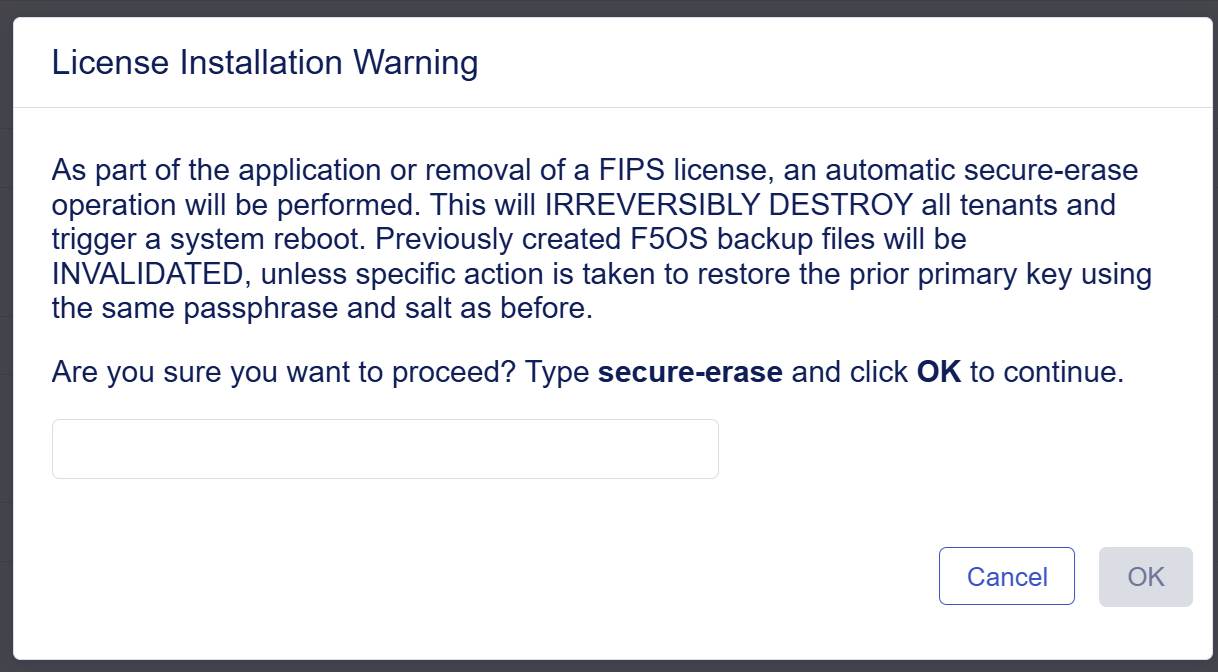
Click OK to continue license installation with a secure-erase operation performed.
The system is now licensed. If a base registration key or add-on key fails to activate, try re-activating the license or contact support.f5.com.
You can view information about the software license activated on your system, including license activation and expiration dates, service check date, and licensed modules, from either the system controller or chassis partition webUIs.
-
Log in to the VELOS system controller webUI or the chassis partition webUI using an account with admin access.
-
On the left, click System Settings > Licensing.
-
View the license information for the system.
For automatic VELOS system licensing, the system needs to be able to connect to the F5 licensing server either through the internet or another means of networking. You need to have the Base Registration Key (five sets of characters separated by hyphens) provided by F5, and any add-on keys (two sets of 7 characters separated by a hyphen) that you have purchased. The Base Registration Key with associated add-on keys are pre-installed on a new VELOS system.
You can activate the VELOS system license automatically from the system controller CLI.
-
Connect using SSH to the system controller floating management IP address.
-
Log in to the command line interface (CLI) of the system controller using an account with admin access.
When you log in to the system, you are in user (operational) mode.
-
Change to config mode.
configThe CLI prompt changes to include
(config). -
Apply a license to the chassis.
system licensing install registration-key <*key*>The registration key is optional. If it is not included, the system uses the one that is already pre-installed. If no registration key is found, you receive an error.
This example applies a specified base registration license to the system:
syscon-1-active(config)# system licensing install registration-key I1234-12345-12345-12345-1234567 result License installed successfully. -
Apply any add-on keys.
system licensing install add-on-keys <*add-on-keys*>This example enables the additional features associated with the three specified add-on-keys, along with the entitlements of the base registration key:
syscon-1-active(config)# system licensing install
 add-on-keys [1234567-1234567 2345678-2345678 3456789-3456789]
result License installed successfully.
Note: If you are switching between a FIPS license and a non-FIPS license, the following message appears:
As part of the application or removal of a FIPS license, an automatic secure-erase operation will be performed. This will IRREVERSIBLY DESTROY all partitions, resulting in the permanent deletion of all tenants followed by a system reboot. Previously created F5OS backup files will be INVALIDATED, unless specific action is taken to restore the prior primary key using the same passphrase and salt as before. Enter yes to continue license installation with a secure-erase operation performed.
The VELOS system is licensed. The license and any add-on keys apply to all partitions and tenants.
You can activate the VELOS system license manually from the system controller CLI.
-
Connect using SSH to the system controller floating management IP address.
-
Log in to the command line interface (CLI) of the system controller using an account with admin access.
When you log in to the system, you are in user (operational) mode.
-
Change to config mode.
configThe CLI prompt changes to include
(config). -
Get the system dossier.
system licensing get-dossier [registration-key XXXXX-XXXXX-XXXXX-XXXXX-XXXXXXX]The registration key is optional. If it is not included, the system uses the one already pre-installed. If no registration key is found, you receive an error.
The dossier for the system displays.
-
Get the license file using the dossier output you just received by going to the F5 site activate.f5.com/license/dossier.jsp.
-
Install the license.
-
Copy the license file text.
-
Run the manual install command and press Enter:
system licensing manual-install license -
Paste the license file content in multiline mode, then press Ctrl+D.
syscon-1-active(config)# system licensing manual-install license Value for 'license' (<string>): [Multiline mode, exit with ctrl-D.] > -
The VELOS system is licensed. The license applies to all of the chassis partitions and tenants.
For automatic VELOS system licensing, the system needs to be able to connect to the F5 licensing server either through the Internet or another means of networking. You need to have the Base Registration Key (five sets of characters separated by hyphens) provided by F5, and any add-on keys (two sets of 7 characters separated by a hyphen) that you have purchased. The Base Registration Key with associated add-on keys are pre-installed on a new VELOS system.
You can activate the VELOS system license automatically from the CLI.
-
Connect using SSH to the system controller floating management IP address.
-
Log in to the command line interface (CLI) of the system controller using an account with admin access.
When you log in to the system, you are in user (operational) mode.
-
Change to config mode.
configThe CLI prompt changes to include
(config). -
Apply a license to the system.
system licensing install registration-key <*key*> proxy-server <*protocol://domain name:port*> proxy-username <*name*> proxy-password <*input*>The registration key is optional. If it is not included, the system uses the one that is already pre-installed. If no registration key is found, you receive an error.
This example applies a specified base registration license to the system:
syscon-1-active(config)# system licensing install registration-key Y0922-72141-80658-12653-0642460 proxy-server http://192.0.2.20:3128 proxy-username root proxy-password Value for 'proxy-password' (<AES encrypted string>): ******* result License installed successfully. -
Apply any add-on keys.
system licensing install add-on-keys <*add-on-keys*>This example enables the additional features associated with the three specified add-on-keys, along with the entitlements of the base registration key:
syscon-1-active(config)# system licensing install
 add-on-keys [1234567-1234567 2345678-2345678 3456789-3456789]
result License installed successfully.
The VELOS system is licensed with proxy server. The license and any add-on keys apply to the system and all tenants.
You can display the license of a VELOS system from the system controller CLI.
-
Connect using SSH to the system controller floating management IP address.
-
Log in to the command line interface (CLI) of the system controller using an account with admin access.
When you log in to the system, you are in user (operational) mode.
-
Display the system license in a simple form.
show system licensingA summary similar to this example displays:
syscon-1-active# show system licensing system licensing license Licensed version 7.4.0 Registration Key Gxxxx-xxxxx-xxxxx-xxxxx-xxxxxxxx Licensed date 2021/01/01 License start 2021/04/16 License end 2022/01/01 Service check date 2021/12/02 Platform ID F101 Appliance SN chs600144s Active Modules Local Traffic Manager, CX410 (Exxxxxx-xxxxxx) Best Bundle, CX410 APM-Lite Carrier Grade NAT (AFM ONLY) Max Compression, CX410 Rate Shaping Max SSL, CX410 Advanced Firewall Manager, CX410 Access Policy Manager, Base, CX410 Anti-Virus Checks Base Endpoint Security Checks Firewall Checks Machine Certificate Checks Network Access Protected Workspace Secure Virtual Keyboard APM, Web Application App Tunnel Remote Desktop Advanced Routing, CX410 Advanced Web Application Firewall, CX410 DNS, Max QPS, CX410 -
Display the raw license file content that was received from the F5 license server.
show running-config system licensing
The VELOS system is licensed. The license applies to all of the chassis partitions and tenants.
You can configure general system settings for the VELOS system, such as system hostname, login banner, and message of the day (MOTD) banner. Depending on which setting you want to configure, you can use either the CLI or the webUI.
You can configure general system settings, including hostname, login banner, message of the day (MOTD) banner, and an advisory banner from the system controller webUI. When enabled and configured, the advisory banner will display at the top of the webUI after authentication. The product name displays but cannot be changed.
-
Log in to the VELOS system controller webUI using an account with admin access.
-
On the left, click System Settings > General.
-
To configure the settings, click edit icon.
-
For Hostname, enter a custom hostname for the system.
-
For Login Banner, enter any text to be displayed when users log in to the system.
-
For MOTD Banner, enter any text to be displayed as a MOTD when users log in to the system.
-
For Advisory Banner, select Enabled or Disabled.
-
For Advisory Banner Color, select the color for the banner.
-
For Advisory Banner Text, enter the text for the banner. The maximum number of characters is 80.
-
Click Save.
You can configure general system settings, including login banner, message of the day (MOTD) banner, advisory banner, and time zone/location from the chassis partition webUI. When enabled and configured, the advisory banner will display at the top of the webUI after authentication.
-
Log in to the command line interface (CLI) of the chassis partition using an account with admin access.
When you log in to the system, you are in user (operational) mode.
-
On the left, click System Settings > General.
-
In the Properties section, click the edit icon to modify the configuration.
-
For Login Banner, enter any text to be displayed when users log in to the chassis partition.
-
For MOTD Banner, enter any text to be displayed as a MOTD when users log in to the chassis partition.
-
For Advisory Banner, select Enabled or Disabled.
-
For Advisory Banner Color, select the color for the banner.
-
For Advisory Banner Text, enter the text for the banner. The maximum number of characters is 80.
-
From Time Zone/Locations, select the time zone region.
-
Click Save.
You can manually configure the hostname for your system from either the system controller or chassis partition CLI. F5 recommends you to configure a Fully Qualified Domain Name (FQDN) hostname.
-
Log in to the command line interface (CLI) of the system controller or chassis partition using an account with admin access.
When you log in to the system, you are in user (operational) mode.
-
Change to config mode.
configThe CLI prompt changes to include
(config). -
Change the hostname.
system config hostname <*hostname*>The minimum length is 1 character, and the maximum length is 253 characters.
In the examples below, you can see the hostname for the system either set to ’test-hostname’ or ‘f5lab.f5net.com’:
syscon-1-active(config)# system config hostname test-hostnamesyscon-1-active(config)# system config hostname f5lab.f5net.comNote: You can set a Fully Qualified Domain Name (FQDN) or plain text as a hostname.
-
Commit the configuration changes.
commitNote: The system hostname is now updated. By default, the system hostname will be included in the subsequent logs.
-
To verify the hostname included in the logs.
show system logging state include-hostnameIn this example, the hostname is included in the logs:
syscon-1-active# show system logging state include-hostname true
The system hostname is now updated.
You can manually configure the log settings to include hostname that is configured for your system in the subsequent logs from the CLI.
-
Log in to the command line interface (CLI) of the system controller or chassis partition using an account with admin access.
When you log in to the system, you are in user (operational) mode.
-
Change to config mode.
configThe CLI prompt changes to include
(config). -
To include hostname in the logs, set ‘include-hostame’ to true.
system logging config include-hostname <*\{ false \| true \}*>Note: The default value is set to true.
In this example, the configured system hostname is included in the logs:
syscon-1-active(config)# system logging config include-hostname true -
Commit the configuration changes.
commit -
Return to user (operational) mode.
end -
To verify the hostname is included in the subsequent logs.
show system logging state include-hostnameIn the examples below, the system hostname “test-hostname” or “f5lab.f5net.com” is included in the logs:
test-hostname# show system logging system logging state include-hostname true test-hostname#f5lab.f5net.com# show system logging system logging state include-hostname true f5lab.f5net.com#
The system hostname is now included in the subsequent logs.
You can configure the login banner for your system manually from either the system controller or chassis partition CLI. The login banner displays before users log in to each respective system.
-
Log in to the command line interface (CLI) of the system controller or chassis partition using an account with admin access.
When you log in to the system, you are in user (operational) mode.
-
Change to config mode.
configThe CLI prompt changes to include
(config). -
Change the login banner text.
system config login-bannerIn this example, you change the login banner text to notify users that unauthorized access is prohibited:
syscon-1-active(config)# system config login-banner (<string>): [Multiline mode, exit with ctrl-D.] UNAUTHORIZED ACCESS TO THIS DEVICE IS PROHIBITED -
Commit the configuration changes.
commit
The login banner is now updated.
You can manually configure the message-of-the-day (MOTD) banner for your system from either the system controller or chassis partition CLI. The MOTD banner displays after users log in to each respective system.
-
Log in to the command line interface (CLI) of the system controller or chassis partition using an account with admin access.
When you log in to the system, you are in user (operational) mode.
-
Change to config mode.
configThe CLI prompt changes to include
(config). -
Change the MOTD banner text.
system config motd-bannerIn this example, you change the login banner text to notify users of upcoming system maintenance:
syscon-1-active(config)# system config motd-banner (<string>): [Multiline mode, exit with ctrl-D.] ATTENTION! This system is scheduled for maintenance in two days. -
Commit the configuration changes.
commit
The MOTD banner is now updated.
You can verify the current MAC allocation data from the system controller CLI.
-
Log in to the command line interface (CLI) of the system controller using an account with admin access.
When you log in to the system, you are in user (operational) mode.
-
Display the current MAC allocation data.
show system mac-allocationA summary similar to this example displays:
syscon-1-active# show system mac-allocation
system mac-allocation state free-single-macs 144
system mac-allocation state allocated-single-macs 16
system mac-allocation state free-large-blocks 24
system mac-allocation state allocated-large-blocks 0
system mac-allocation state total-free-mac-count 912
system mac-allocation state total-allocated-mac-count 16
system mac-allocation state total-mac-count 928
You can verify the current runtime status of the MAC pool from the system controller CLI.
-
Log in to the command line interface (CLI) of the system controller using an account with admin access.
When you log in to the system, you are in user (operational) mode.
-
Display the current chassis MAC allocation.
show system chassis-macsA summary similar to this example displays:
syscon-1-active# show system chassis-macs
system chassis-macs base 000a49ff1800
                                                                                    ALLOCATED
IDENTIFIER  UUID                                  OFFSET  MAC ADDRESS        INDEX  AS SINGLE
-----------------------------------------------------------------------------------------------
1           c2c66fb4-7426-4134-8110-a0fb4547c866  8       00:0a:49:ff:18:08  -      -
                                                  9       00:0a:49:ff:18:09  -      -
                                                  10      00:0a:49:ff:18:0a  -      -
                                                  11      00:0a:49:ff:18:0b  -      -
                                                  12      00:0a:49:ff:18:0c  -      -
                                                  13      00:0a:49:ff:18:0d  -      -
                                                  14      00:0a:49:ff:18:0e  -      -
                                                  15      00:0a:49:ff:18:0f  -      -
                                                  16      00:0a:49:ff:18:10  -      -
                                                  17      00:0a:49:ff:18:11  -      -
                                                  18      00:0a:49:ff:18:12  -      -
                                                  19      00:0a:49:ff:18:13  -      -
                                                  20      00:0a:49:ff:18:14  -      -
                                                  21      00:0a:49:ff:18:15  -      -
                                                  22      00:0a:49:ff:18:16  -      -
                                                  23      00:0a:49:ff:18:17  -      -
                                                  28      00:0a:49:ff:18:1c  0      false
                                                  29      00:0a:49:ff:18:1d  0      false
                                                  30      00:0a:49:ff:18:1e  0      false
                                                  31      00:0a:49:ff:18:1f  0      false
                                                  32      00:0a:49:ff:18:20  0      false
                                                  33      00:0a:49:ff:18:21  0      false
                                                  34      00:0a:49:ff:18:22  0      false
                                                  35      00:0a:49:ff:18:23  0      false
                                                  36      00:0a:49:ff:18:24  0      false
                                                  37      00:0a:49:ff:18:25  0      false
                                                  38      00:0a:49:ff:18:26  0      false
                                                  39      00:0a:49:ff:18:27  0      false
                                                  40      00:0a:49:ff:18:28  0      false
                                                  41      00:0a:49:ff:18:29  0      false
                                                  42      00:0a:49:ff:18:2a  0      false
                                                  43      00:0a:49:ff:18:2b  0      false
                                                  44      00:0a:49:ff:18:2c  0      false
                                                  45      00:0a:49:ff:18:2d  0      false
                                                  46      00:0a:49:ff:18:2e  0      false
                                                  47      00:0a:49:ff:18:2f  0      false
                                                  48      00:0a:49:ff:18:30  0      false
                                                  49      00:0a:49:ff:18:31  0      false
                                                  50      00:0a:49:ff:18:32  0      false
                                                  51      00:0a:49:ff:18:33  0      false
                                                  52      00:0a:49:ff:18:34  0      false
                                                  53      00:0a:49:ff:18:35  0      false
                                                  54      00:0a:49:ff:18:36  0      false
                                                  55      00:0a:49:ff:18:37  0      false
                                                  56      00:0a:49:ff:18:38  0      false
                                                  57      00:0a:49:ff:18:39  0      false
                                                  58      00:0a:49:ff:18:3a  0      false
                                                  59      00:0a:49:ff:18:3b  0      false
You can verify the system uptime for the CLI:
-
Log in to the command line interface (CLI) of the system controller using an account with admin access.
When you log in to the system, you are in user (operational) mode.
-
Display the system uptime.
show system uptimeA summary similar to this example displays:
syscon-1-active# show system uptime
system uptime state up-time "6h, 26m, 0s"
If you are having an issue with a chassis partition (such as unusually high CPU or memory usage or lockup), it is possible that rebooting a blade in the chassis partition might help to resolve the issue.
When there is a problem, the system sends alerts that you would see on the dashboard or on the Alarms & Events screen. A blade status of Not ready for a prolonged time on the General screen can also indicate the need to reboot the blade. You should rarely have to reboot a blade, however, because typically if the VELOS system needs to reboot a blade, it will do so automatically without administrator intervention. F5 recommends working with customer support if you think a blade reboot is necessary.
You can manually reboot a system controller in your VELOS system from the system controller CLI.
-
Connect using SSH to the system controller floating management IP address.
-
Log in to the command line interface (CLI) of the system controller using an account with admin access.
When you log in to the system, you are in user (operational) mode.
-
Reboot a system controller.
system reboot controllers controller { active | standby ]In this example, you reboot the standby system controller:
syscon-1-active# system reboot controllers controller standby
The specified system controller reboots.
You can reboot a system controller from the system controller webUI.
-
Log in to the VELOS chassis partition webUI using an account with admin access.
-
On the left, click System Settings > General.
-
Undert the System Operations & Statussection, review the status of the system controllers.
The Reboot button will not be available for a system controller that is currently being rebooted.
-
If you decide that a reboot is necessary, click Reboot to the right of the system controller that you want to reboot.
If the system controller has the active role, a popup displays asking you to confirm the reboot operation. This causes a failover to the standby controller.
The It takes a few minutes for the system controller to reboot. The status will show
Reboot in progress, thenNot ready, and when reboot is complete, it saysReady.
You can manually reboot a blade in your system from the chassis partition CLI.
-
Connect using SSH to the chassis partition management IP address.
-
Log in to the command line interface (CLI) of the chassis partition using an account with admin access.
When you log in to the system, you are in user (operational) mode.
-
Reboot a blade.
cluster nodes node <*blade-number*> rebootIn this example, you reboot blade-1:
default-1#(config) cluster nodes node blade-1 reboot
The specified blade reboots.
You can reboot a blade within a chassis partition from the chassis partition webUI.
-
Log in to the VELOS chassis partition webUI using an account with admin access.
-
On the left, click System Settings > General.
-
Undert the System Operations & Statussection, review the status of each of the blades in the chassis partition.
The Reboot button will not be available for slots that do not have blades present, or for blades that are currently being rebooted.
-
If you have tenants running on the chassis partition you might want to warn users that their service might be interrupted temporarily.
-
If you decide that a reboot is necessary, click Reboot to the right of the slot containing the blade that you want to reboot.
It takes a few minutes for the blade to reboot. The status will show
Reboot in progress, thenNot ready, and when reboot is complete, it saysReady.
On-demand FIPS integrity checks on the VELOS platforms allows you to configure and monitor the integrity check settings for Controllers, Partitions, and Blades. These settings are available only on the FIPS licensed devices.
You can run integrity check for the system from the webUI.
-
Log in to the VELOS system controller webUI using an account with admin access.
-
On the left, click System Settings > FIPS Integrity Check.
-
Under the section Controllers Integrity Check,
Here you can manage and monitor the integrity check process for device controllers.
-
Enter the Theshold Value and click Update.
-
Click Run button next to a controller to initiate an integrity check.
A confirmation popup will appear for user acknowledgment. Upon confirmation, the integrity check will begin, and the status is displayed.
-
-
In the Integrity Check area, enter the Theshold Value and click Update.
-
Under the section Partitions Integrity Check,
Here you to view the integrity status of all configured partitions and perform integrity checks.
-
Click Run button next to the desired partition.
A confirmation popup will appear for user acknowledgment. Upon confirmation, the integrity check will begin, and the status is displayed.
-
-
Under the section Blades Integrity Check,
Here you to view the integrity status of all the blades and perform integrity checks
-
Click Run button next to the desired partition.
A confirmation popup will appear for user acknowledgment. Upon confirmation, the integrity check will begin, and the status is displayed.
-
You can run controllers integrity check for the system from the CLI.
-
Log in to the command line interface (CLI) of the system using an account with admin access.
When you log in to the system, you are in user (operational) mode.
-
Change to config mode.
configThe CLI prompt changes to include
(config). -
Configure the threshold value,
system security integrity-check config threshold-valueThe range is from 0 to 10.
-
Run Integrity check for the system
system security integrity-check controllers controller 2 run-integrity-check proceed { no | yes }A summary to this example dsiplays:
syscon-2-active(config)# system security integrity-check controllers controller 2 run-integrity-check proceed yes
response Integrity check is triggered successfully. It will take some time to complete.
syscon-2-active(config)# exi
You can run controllers integrity check for the system from the CLI.
-
Log in to the command line interface (CLI) of the system using an account with admin access.
When you log in to the system, you are in user (operational) mode.
-
Change to config mode.
configThe CLI prompt changes to include
(config). -
Run Integrity check for the system
partitions partition run-integrity-check <partition-name> proceed { no | yes }