Manual Chapter : Deploying AFM in ADC Mode

Applies To:

Show Versions Show Versions

BIG-IP AFM

  • 14.1.2, 14.1.0
Manual Chapter

Deploying AFM in ADC Mode

Deploying AFM in ADC mode

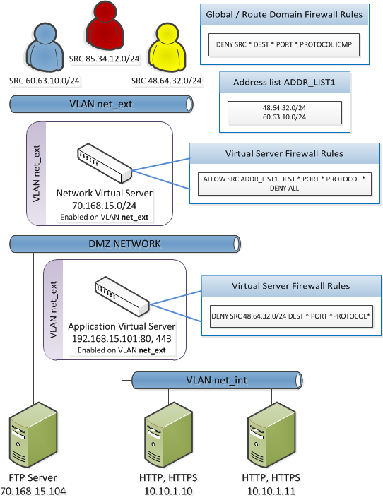
By default, AFM firewall is configured in ADC mode, which is a default allow configuration. In ADC mode, all traffic is allowed through the firewall, and any traffic you want to block must be explicitly specified.

To understand this firewall scenario, imagine that your prerequisite system load-balances all traffic from the Internet to several internal servers. The internal servers are:

Virtual servers IP address
Network virtual server 70.168.15.0/24
Application virtual server 192.168.15.101

In order for traffic from the internal application virtual server to reach the external network virtual server, you must create a VLAN and enable both internal and external virtual servers on it. In this scenario, these VLANs are specified:

VLAN Configuration
net_ext Enabled on 70.168.15.0/24, 192.168.15.101
net_int Includes pool members 10.10.1.10, 10.10.1.11

In this firewall configuration, there are three external networks that require firewall policies:

Network Policy
60.63.10.0/24 Allow all access
48.64.32.0/24 Allow all access
85.34.12.0/24 Deny all access
To set up this scenario, you configure firewall rules specific to these networks. You will also configure a firewall rule that denies all ICMP traffic, to prevent pinging of network devices.

ADC mode configuration scenario

Network firewall ADC mode example

Configuration settings for IPv6 pools and ADC mode

In a standard configuration, IPv6 pools work with either ADC mode or Firewall mode without any issues. However, in the specific ADC mode configuration where a Deny All policy is added after any specific Allow rules are configured, IPv6 pools cannot be reached.
If you choose to add a rule to deny all traffic after more specific rules, you must add a preceding rule with the following parameters.
  • State: Enabled
  • Protocol: ICMPv6 (58)
  • Type: Neighbor Advertisement (136)
  • Source Address: any affected pool members
  • Destination Address: the BIG-IP address, or Any
  • Action: Accept
  • All other values can be left at their defaults, except the rule name.

Such a rule allows ICMPv6 pools to function, when a rule that denies all traffic is added at the end of the rule list in an ADC mode configuration.

Configure AFM to use ADC mode

This task describes how to configure AFM to use ADC mode. In this mode, all network traffic is allowed.
Note: ADC mode is the default mode.
  1. On the Main tab, click Security > Options > Network Firewall .
  2. From the Virtual Server & Self IP Contexts list, select the default action Accept for the self IP and virtual server contexts.
  3. From the Global Context list, select the default action for the global rule context.
    • Select Drop to silently drop all traffic. Dropping causes the connection to be retried until the retry threshold is reached.
    • Select Reject to reject all traffic. Rejecting sends a destination unreachable message to the sender.
  4. Click Update.

Creating a VLAN for the network firewall

Create a VLAN with tagged interfaces, so that each of the specified interfaces can process traffic destined for that VLAN.
  1. On the Main tab, click Network > VLANs .
    The VLAN List screen opens.
  2. Click Create.
    The New VLAN screen opens.
  3. In the Name field, type a unique name for the VLAN.
    For purposes of this implementation, name the VLAN net_ext.
  4. For the Interfaces setting:
    1. From the Interface list, select an interface number.
    2. From the Tagging list, select Tagged.
    3. Click Add.
  5. If you want the system to verify that the return route to an initial packet is the same VLAN from which the packet originated, select the Source Check check box.
  6. From the Configuration list, select Advanced.
  7. In the MTU field, retain the default number of bytes (1500).
  8. If you want to base redundant-system failover on VLAN-related events, select the Fail-safe check box.
  9. From the Auto Last Hop list, select a value.
  10. From the CMP Hash list, select a value.
  11. To enable the DAG Round Robin setting, select the check box.
  12. For the Hardware SYN Cookie setting, select or clear the check box.
    When you enable this setting, the BIG-IP system triggers hardware SYN cookie protection for this VLAN.
    Enabling this setting causes additional settings to appear. These settings appear on specific BIG-IP platforms only.
  13. For the Syncache Threshold setting, retain the default value or change it to suit your needs.
    The Syncache Threshold value represents the number of outstanding SYN flood packets on the VLAN that will trigger the hardware SYN cookie protection feature.

    When the Hardware SYN Cookie setting is enabled, the BIG-IP system triggers SYN cookie protection in either of these cases, whichever occurs first:

    • The number of TCP half-open connections defined in the LTM setting Global SYN Check Threshold is reached.
    • The number of SYN flood packets defined in this Syncache Threshold setting is reached.
  14. For the SYN Flood Rate Limit setting, retain the default value or change it to suit your needs.
    The SYN Flood Rate Limit value represents the maximum number of SYN flood packets per second received on this VLAN before the BIG-IP system triggers hardware SYN cookie protection for the VLAN.
  15. Click Finished.
    The screen refreshes, and it displays the new VLAN in the list.
The new VLAN appears in the VLAN list.
Enable the new VLAN on both the network virtual server and the application virtual server.

Configuring an LTM virtual server with a VLAN for Network Firewall

For this implementation, at least two virtual servers and one at least one VLAN are assumed, though your configuration might be different.
You enable two virtual servers on the same VLAN to allow traffic from hosts on one virtual server to reach or pass through the other. In the Network Firewall, if you are using multiple virtual servers to allow or deny traffic to and from specific hosts behind different virtual servers, you must enable those virtual servers on the same VLAN.
Tip: By default, the virtual server is set to share traffic on All VLANs and Tunnels. This configuration will work for your VLANs, but in the firewall context specifying or limiting VLANs that can share traffic provides greater security.
  1. On the Main tab, click Local Traffic > Virtual Servers .
    The Virtual Server List screen opens.
  2. Click the name of the virtual server you want to modify.
  3. From the VLAN and Tunnel Traffic list, select Enabled on. Then, for the VLANs and Tunnels setting, move the VLAN or VLANs on which you want to allow the virtual servers to share traffic from the Available list to the Selected list.
  4. Click Update to save the changes.
  5. Repeat this task for all virtual servers that must share traffic over the VLAN.
The virtual servers on which you enabled the same VLAN can now pass traffic.

Adding a firewall rule to deny ICMP

Use this task to create a firewall rule at the Global context, that denies ICMP packets globally.
  1. On the Main tab, click Security > Network Firewall > Active Rules .
    The Active Rules screen opens.
  2. In the Rules area, click Add to add a firewall rule to the list.
  3. From the Context list, select the Global context.
  4. In the Name field, type deny_icmp.
  5. From the Type list, select Rule.
  6. From the State list, select Enabled.
  7. From the Protocol list, select ICMP.
  8. In the ICMP Message area, from the Type list, select Any, and click the Add button.
    Tip: You can optionally deny only ICMP ping requests, by selecting Echo (8) from the Type list, and clicking Add.
  9. Leave the Source area configured to allow Any address, port, and VLAN.
  10. Leave the Destination area configured to allow Any address or port.
  11. From the Action list, select Drop or Reject.
    These options either drop ICMP packets from any source and port to any port and address, or send a reject message and reset the the connection.
  12. From the Logging list, enable or disable logging for the firewall rule.
    A logging profile must be enabled to capture logging info for the firewall rule.
  13. Click Finished.
    The list screen and the new item are displayed.
A new firewall rule is created, and appears in the firewall rule list. This firewall rule denies all access to and from all sources and destinations on the ICMP protocol.

Creating address lists

Use this procedure to create the address lists to be used in the firewall rules.
  1. On the Main tab, click Shared Objects > Address Lists .
  2. Click Create.
  3. In the name field, type addr_list1.
  4. In the Addresses area, add the following addresses: 48.63.32.0/24 and 60.63.10.0/24. Click Add after you type each address.
  5. Click Repeat.
  6. In the name field, type addr_list2.
  7. In the Addresses area, add the following address: 85.34.12.0/24.
  8. Click Add.
  9. Click Finished.
The list screen and new address lists are displayed

Creating firewall rule lists

Create the AFM firewall rule lists that will contain the firewall rules.
  1. On the Main tab, click Security > Network Firewall > Rule Lists .
    The Rule Lists screen opens.
  2. Click the Create button to create a new rule list.
  3. In the Name field, type allow_rule_list.
  4. Click Repeat.
  5. In the Name field, type deny_rule_list.
  6. Click Finished.
The empty firewall rule list is displayed.

Adding the firewall rules to the rule list

Add network firewall rules to a rule list so you can collect and apply them at once in a policy. Use this task to create firewall rule list that allows traffic only from the networks in address list addr_list1 and another firewall rule list that denies traffic only in address list addr_list2.
  1. On the Main tab, click Security > Network Firewall > Rule Lists .
    The Rule Lists screen opens.
  2. From the list, click allow_rule_list.
    The Rule List properties screen opens.
  3. In the Rules area, click Add to add a firewall rule to the list.
  4. In the Name field, type allow_addr_list.
  5. From the Source Address/Region list, select Specify.
  6. Click Address List and select addr_list1.
  7. Click Add.
  8. From the Action list, select Accept.
  9. From the Logging list, enable or disable logging for the firewall rule.
    A logging profile must be enabled to capture logging info for the firewall rule.
  10. Click Repeat.
  11. In the Name field, type deny_all.
  12. From the Source Address/Region, select Any.
  13. From the Action list, select Reject.
  14. Click Finished.
  15. Click Network Firewall : Rule Lists at the top of the page.
  16. From the list, click deny_rule_list.
    The Rule List properties screen opens.
  17. In the Rules area, click Add to add a firewall rule to the list.
  18. In the Name field, type deny_addr_list.
  19. From the Source Address/Region list, select Specify.
  20. Click Address List and select addr_list2.
  21. Click Add.
  22. From the Action list, select Reject.
  23. From the Logging list, enable or disable logging for the firewall rule.
    A logging profile must be enabled to capture logging info for the firewall rule.
  24. Click Finished.
    The Rule List properties screen opens.
The Rule Lists screen shows the new rule in the rule list.

Creating firewall policies

Create the firewall policies to collect the rule list. The policies will later be applied to the virtual servers.
  1. On the Main tab, click Security > Network Firewall > Policies .
    The Policies screen opens.
  2. Click Create to create a new policy.
  3. In the Name field, type network_virtual_policy.
  4. Click Repeat.
  5. In the Name field, type app_virtual_policy.
  6. Click Finished.
The Policies screen shows the new policy in the policy list.

Activating the rule list in the policy

The rule list is a container in which you can select and activate one of the rule lists that you created previously, or one of the predefined system rule lists, to apply a collection of rules at one time, to a policy.
  1. On the Main tab, click Security > Network Firewall > Policies .
    The Policies screen opens.
  2. Click the firewall policy named network_virtual_policy.
  3. Click Add Rule List.
  4. In the Name section, enter allow_rule_list in the Rule List option.
  5. Click Done Editing.
  6. Click Commit Changes to System at the top of the page.
  7. Click Policies at the top of the page.
  8. Click the firewall policy named app_virtual_policy.
  9. Click Add Rule List.
  10. In the Name section, enter deny_rule_list in the Rule List option.
  11. Click Done Editing.
  12. Click Commit Changes to System at the top of the page.
The firewall policy and rule list are activated.

Associating the firewall policies with the virtual servers

In the final steps, the firewall policies are applied to the virtual servers.
  1. On the Main tab, click Local Traffic > Virtual Servers .
  2. Click the name of the virtual server with Destination IP address 70.186.15.0/24.
  3. Click Security > Policies at the top of the page.
  4. Change Network Firewall Enforcement to Enabled.
  5. From the Policy list, select network_virtual_policy.
  6. Click Update.
  7. Click Virtual Servers : Virtual Server List at the top of the page.
  8. Click the name of the virtual server with Destination IP address 192.168.15.101.
  9. Click Security > Policies at the top of the page.
  10. Change Network Firewall Enforcement to Enabled.
  11. From the Policy list, select app_virtual_policy.
  12. Click Update.