Applies To:
Show Versions
BIG-IP DNS
- 12.1.5, 12.1.4, 12.1.3, 12.1.2, 12.1.1, 12.1.0
Configuring BIG-IP DNS to Determine PGW Health and Availability
Overview: Configuring BIG-IP DNS to determine packet gateway health and availability
Service providers can configure the BIG-IP® DNS system to increase the availability of their customer services on the System Architecture Evolution (SAE) network. One way is to configure a GTP monitor for the health and availability of a packet gateway (PGW). The GTP monitor issues an echo request to a list of PGW systems. If a PGW fails to respond to the GTP echo request, it is marked as down, and removed from the list of available PGW systems that are returned to an MME in a DNS response. BIG-IP DNS can also be configured to load balance DNS queries for the access point name (APN) across the PGW systems that are active and available.
This illustration presents a simplified depiction of how the process works on the SAE network.
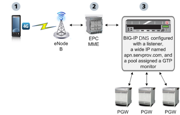
BIG-IP DNS monitoring packet gateways
- A smartphone that is preprogrammed with an APN, for example, apn.servprov.com, initiates a data connection.
- The EPC MME performs a DNS lookup on apn.servprov.com in order to select a packet gateway.
- BIG-IP DNS handles the DNS request and returns only IP addresses for PGW systems that are active and available.
Task summary
Configure BIG-IP DNS using these tasks to determine PGW system health and availability, and to load balance DNS queries across the active and available PGW systems.Defining a data center
Defining BIG-IP DNS systems
Defining packet gateway systems
Creating listeners to identify DNS traffic for an APN
Creating a custom GTP monitor
Create a custom GTP monitor to detect the presence and health of a packet gateway (PGW) system. The GTP monitor issues a GTP echo request, and if the PGW system fails to respond, it is automatically marked as down and removed from the available list of PGW systems that the BIG-IP® system returns to an MME.
Creating a pool of packet gateway systems with an applicable pool type
- Create servers to represent the PGW systems, and manually add at least one virtual server or wide IP to each server.
- Create a GTP monitor.


