Manual Chapter :
Configuring BIG-IP DNS on a Network with One Route Domain
Applies To:
Show Versions
BIG-IP DNS
- 13.0.1, 13.0.0
Overview: How do I deploy BIG-IP DNS on a network with one route domain?
You can deploy BIG-IP® DNS on a network where BIG-IP Local Traffic Manager™ (LTM®) is configured with one route domain and no overlapping IP addresses.
CAUTION:
For BIG-IP systems that include both LTM and BIG-IP DNS, you can configure route
domains on internal interfaces only. F5 Networks does not support the configuration of route
domains on a standalone BIG-IP DNS.
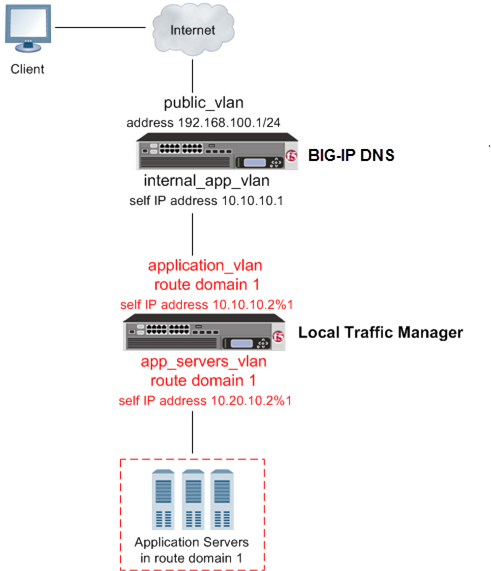
BIG-IP DNS deployed on a network in front of a BIG-IP LTM configured with a route domain
Task summary
Perform these tasks to configure a route domain, and then to configure BIG-IP DNS to be able to monitor the LTM systems.
Creating VLANs for a route domain on BIG-IP LTM
You need to create two VLANs on BIG-IP®
LTM® through which traffic can pass to a route domain.
Repeat this procedure, but in Step 3, name the VLAN
internal.
Creating a route domain on the BIG-IP system
Before you create a route domain:
- Ensure that an external and an internal VLAN exist on the BIG-IP® system.
- If you intend to assign a static bandwidth controller policy to the route domain, you must first create the policy. You can do this using the BIG-IP Configuration utility.
- Verify that you have set the current partition on the system to the partition in which you want the route domain to reside.
You can create a route domain on BIG-IP system to segment (isolate) traffic on your
network. Route domains are useful for multi-tenant configurations.
You now have another route domain on the BIG-IP system.
Creating a self IP address for a route domain on BIG-IP LTM
Ensure that external and internal VLANs exist on BIG-IP®
LTM®, before you begin creating a self IP address for a route
domain.
Create a self IP address on LTM that resides in the address space of the route
domain.
Repeat all steps, but in Step 6 (from the VLAN/Tunnel list)
select VLAN internal.
Defining a server for a route domain on BIG-IP DNS
Ensure that at least one data center exists in the configuration.
On a BIG-IP®
DNS system, define a server that represents the route domain.
Running the big3d_install script
Determine the self IP addresses of the BIG-IP® systems that you want
to upgrade with the latest big3d agent. Ensure that port
22 is open on these systems.
Run the big3d_install script on the DNS system
you are adding to your network. This upgrades the big3d agents on the other BIG-IP
systems on your network. It also instructs these systems to authenticate with the other BIG-IP
systems through the exchange of SSL certificates. For additional information about running the
script, see K13312 on AskF5.com (www.askf5.com).
Note: You must perform this task from the command-line
interface.
Important: All target BIG-IP systems
must be running the same or an older version of BIG-IP software.
The SSL certificates are exchanged, authorizing communications between the systems. The
big3d agent on each system is upgraded to the same version as is installed on
the BIG-IP DNS system from which you ran the script.
Running the bigip_add script
You must determine the self IP addresses of
the LTM® systems that you want to communicate with BIG-IP® DNS before you start this task.
You run the bigip_add script on the BIG-IP DNS
system you are installing on a network that includes other BIG-IP® systems
of the same version. This script exchanges SSL certificates so that each system is authorized to
communicate with the other. For additional information about running the script, see K13312 on
AskF5.com (www.askf5.com).
Note: The BIG-IP DNS and BIG-IP LTM systems must have
TCP port 22 open for the script to work. You must perform this task from
the command-line interface.
The specified BIG-IP systems can now
communicate with BIG-IP DNS.
Implementation result
You now have an implementation in which BIG-IP® DNS can monitor virtual servers on BIG-IP LTM® systems configured with one route domain.


