Applies To:
Show Versions
Deploying Stateless Network Address Translation
Overview: 6rd configuration on BIG-IP systems
The 6rd (rapid deployment) feature is a solution to the IPv6 address transition. It provides a stateless protocol mechanism for tunneling IPv6 traffic from the IPv6 Internet over a service provider's (SP's) IPv4 network to the customer's IPv6 networks. As specified in RFC5969, 6rd uses an SP's own IPv6 address prefix rather than the well-known IPV6 in IPv4 prefix (2002::/16), which means that the operational domain of 6rd is limited to the SP network, and is under the SP's control.
Fully compliant with RFC5969, the BIG-IP® system supports the border relay (BR) functionality by automatically mapping the tunnel's IPv4 address at the customer premises to IPv6 address spaces using the 6rd domain configuration information. Using a BIG-IP system, an SP can deploy a single 6rd domain or multiple 6rd domains. When supporting multiple 6rd domains, a separate tunnel is required to accommodate each 6rd domain, which is specified in the associated 6rd tunnel profile.
When you deploy 6rd using a BIG-IP system as the BR device, you need to create 6rd tunnels using wildcard remote addresses. This implementation documents the configuration of a BIG-IP device as a BR device.
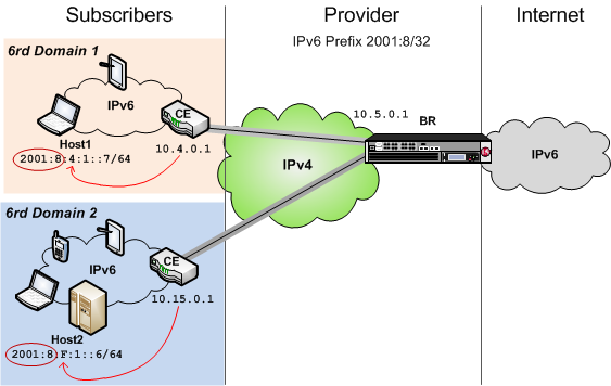
Example of a 6rd configuration
This table shows examples of 6rd parameter values, based on the illustration. You set these values in the v6rd profile you create.
| Setting | Value |
|---|---|
| IPv4 Prefix | 10 |
| IPv4 Prefix Length | 8 |
| IPv6 Prefix | 2001:8:4:1 |
| IPv6 Prefix Length | 64 |
Task summary for 6rd network configuration
Before you configure a 6rd network, ensure that you have licensed and provisioned CGNAT on the BIG-IP system. Also, the BIG-IP system must have an IPv6 address and an IPv6 default gateway.
Task list
Using a profile to define a 6rd domain
Configuring a BIG-IP system as a border relay (BR) device
Creating a forwarding virtual server for a tunnel
Assigning a self IP address to an IP tunnel endpoint
Routing traffic through a 6rd tunnel interface
Overview: MAP configuration on BIG-IP systems
Mapping of Address and Port (MAP) is an IPv4 to IPv6 transition technology. The BIG-IP® system plays the role of the border relay (BR) in a MAP deployment. At the time of this writing, the implementation of MAP on the BIG-IP system complies with the IETF Standards Track draft Mapping of Address and Port with Encapsulation (MAP) draft-ietf-software-map-10.
This illustration shows the position of a BIG-IP system in a MAP configuration. As the BR device, the BIG-IP system decapsulates the encapsulated IPv6 traffic and forwards it to the public IPv4 Internet.
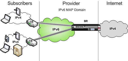
Example of a MAP configuration
About Mapping of Address and Port (MAP)
- MAP-E (Encapsulated), which uses the IPv4-in-IPv6 tunneling approach, is on the IETF standards track, and is now referred to as simply MAP.
- MAP-T (Translated), which uses the IPv4-from/to-IPv6 address translation approach, is on the IETF experimental track.
Both MAP and MAP-T assume that the service provider internal network has already been migrated to IPv6, but the CE is still running dual stack. IPv6 subscribers behind the CE can use regular addressing methods to reach the public IPv6 Internet. MAP focuses on how the CEs should forward IPv4 subscriber traffic to and from the Internet.
About Mapping of Address and Port with Translation (MAP-T)
In a MAP-T deployment, the customer edge (CE) device implements a combination of stateful NAPT44 translation and stateless MAP translation, using a source IPv4 address and port number to forward IPv4 traffic across the upstream IPv6 network. The border relay (BR) is responsible for connecting one or more MAP domains to external IPv4 networks. It converts the inbound IPv6 packet from the CEs back to NAT'd IPv4, using the corresponding MAP configurations.
About Mapping of Address and Port with Encapsulation (MAP)
In a MAP (formerly MAP-E) deployment, the customer edge (CE) device implements a combination of NAPT44 followed by IPv4-in-IPv6 encapsulation. The source IPv6 address of the encapsulating header is derived from the source IPv4 address and port number, according to MAP configurations. At the border relay (BR), the IPv6 traffic is decapsulated to recover the NAT'd IPv4 packet, which the system then forwards to the Internet.
The MAP CE devices and BRs form a MAP domain. The MAP domain is defined by the algorithms and parameters for mapping IPv4 address and port numbers to a subscriber. All CE nodes within the same MAP domain must use the same subnet ID, as configured in the ip4-prefix attribute of the BR configuration, to correctly synthesize the MAP IPv6 address.
MAP relies on port sharing, which means that it supports only ICMP and port-based transport protocols. This excludes PPTP (which uses GRE) and any transports other than TCP, UDP, or ICMP. Because the port sharing ratio and IPv6 prefix are mathematically interdependent, you must correctly size your IPv6 network to ensure that your implementation of MAP accommodates enough subscribers.
The BR handles traffic between itself and a given MAP domain, which means that it has at least one IPv4 interface and one IPv6 interface. Its job is to aggregate the MAP tunnels. Within the MAP Domain, IPv4 traffic follows IPv6 routing, and the BR is reachable using IPv6 anycast addressing for load balancing and resiliency.
The port set ID (PSID) algorithmically represents different groups of non-overlapping, contiguous L4 ports that a CE device can use for port translation, allowing different CE devices to share the same source IPV4 address. As an anti-spoofing measure, the PSID is embedded within the IPv6 address for validation at the BR.
- The BMR enables the CE to provision multiple sets of IPv4 ports (NAT pools) for subscribers to use.
- The BMR allows the CE to construct the associated upstream source MAP IPv6 address;
- The BMR must be applied consistently to all CEs and BRs within a given MAP domain.
Due to the deterministic mapping of IPv4 address and port numbers to subscribers, MAP may originate tunnels heading toward subscribers given the IPv4 flow information.
Task summary for configuring the BIG-IP system as a BR device for a MAP domain
Before you configure the BIG-IP system as a BR device for a MAP domain, ensure that you have licensed and provisioned CGNAT on the BIG-IP system. Also, the BIG-IP system must have an IPv6 self IP address, an IPv6 default gateway, and an IPv4 self IP address on the side of the BIG-IP system that faces the Internet.
Make sure that the CE devices are configured for MAP. For instructions on configuring a CE device, consult the manufacturer's documentation.
Task list
Using a profile to define a MAP domain
Configuring a tunnel for Mapping Address and Port
Creating a forwarding virtual server for IPv4 traffic
After you configure a MAP tunnel to transport IPv4 traffic over an IPv6 network, you need to create a virtual server to intercept the IPv4 traffic and forward the packets to their destinations.
Creating a forwarding virtual server for IPv6 traffic
After you configure a MAP tunnel to transport IPv4 and IPv6 traffic over an IPv6 network, you need to create a virtual server to intercept the IPv6 traffic and forward the packets to their destinations.
Assigning a self IP address to a MAP tunnel endpoint
Assigning a self IP address to a tunnel ensures that the tunnel appears as a resource for routing traffic. This screen snippet shows a sample list of the self IP addresses required on the BIG-IP system for a MAP configuration, including the self IP address of the tunnel.
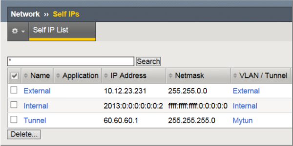
Self IP addresses required for a MAP configuration
- The External self IP address is an IPv4 address on the side of the BIG-IP system that faces the Internet.
- The Internal self IP address is an IPv6 address on the BIG-IP system, which is configured as a BR device.
- The Tunnel self IP address is the one you just created in this task.
Viewing MAP tunnel statistics
This example shows the statistics displayed for the MAP tunnel using the profile map-profile.
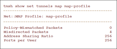
- Spoof Packets: The number of IPv4 packets that fail MAP self-consistency checks.
- Misdirected Packets: The number of IPv4 packets sent to the wrong MAP domain or wrong protocol number.
- Address Sharing Ratio: The number of users sharing one IP address.
- Ports per user: The number of ports each user behind the CE can use.
Overview: Lightweight 4over6 Configuration on BIG-IP systems
Lightweight 4over6 (lw4o6) functionality is an IPv4 to IPv6 transition technology that provides IPv4 service over an IPv6-only network. A lw4o6 configuration refines DS-Lite functionality to reduce the network address and port translation (NAPT44) states in a service provider's network. In a lw4o6 configuration, lwB4 customer edge (CE) devices, provisioned with a public IP address and a port set, perform NAPT, as well as encapsulation and decapsulation. The implementation of lw4o6 on the BIG-IP®system complies with RFC 7596.
A lw4o6 configuration includes the following components:
- lwB4. Provides NAPT, as well as encapsulation and decapsulation of IPv4 and IPv6. Each lwB4 must be provisioned with a public IPv4 address and port set, restricting the external ports used by NAPT to source packets.
- lwAFTR. Encapsulates and decapsulates IPv4 and IPv6. It also forwards incoming packets to the applicable lwB4, and forwards outgoing packets to the IPv4 network.
- Provisioning. Configures the lwB4 with the public IPv4 address and port set.
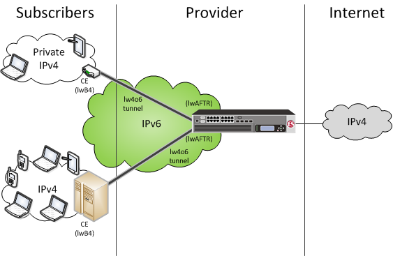
This illustration shows the position of a BIG-IP system in a lw4o6 configuration. The BIG-IP system decapsulates the encapsulated IPv6 traffic and forwards it to the public IPv4 Internet. The reverse sequence is performed for response traffic.
Illustration of a lw4o6 deployment
In this example, a service provider transports encapsulated IPv4 traffic over its IPv6 network.
Example of a lw4o6 configuration
An example lw4o6 table
This topic includes an example of a lw4o6 binding table.
An example lw4o6 table.
-------------------------- # text_csv # psid_len 1 # # IPv4 IPv6 prefix PSID 10.100.10.211, 2015:a000:0000:0000, 0, 10.100.10.211, 2015:a000:0000:0000, 1, 10.100.10.212, 2015:a000:0000:0001, 0, 10.100.10.212, 2015:a000:0000:0001, 1, 10.100.10.213, 2015:a000:0000:0002, 0, 10.100.10.213, 2015:a000:0000:0002, 1, 10.100.10.215, 2015:a000:0000:0003, 0, 10.100.10.215, 2015:a000:0000:0003, 1, #end file
Task summary for using lw4o6 with CGNAT
Before you configure the BIG-IP® system for a lw4o6 domain, ensure that you have licensed CGNAT on the BIG-IP system. Optionally, the BIG-IP system can provide an IPv6 self IP address, an IPv6 default gateway, and an IPv4 self IP address on the side of the BIG-IP system that faces the Internet.
Make sure that the CE devices are configured for lw4o6. For instructions on configuring a CE device, consult the manufacturer's documentation.
Task list
Importing an lw4o6 table
Using a profile to define a lw4o6 domain
Configuring a tunnel for lw4o6
Creating a forwarding virtual server for IPv4 traffic
After you configure an lw4o6 tunnel to transport IPv4 traffic over an IPv6 network, you need to create a virtual server to intercept the IPv4 traffic and forward the packets to their destinations.
Assigning a self IP address to an lw4o6 tunnel endpoint
Assigning a self IP address to a tunnel ensures that the tunnel appears as a resource for routing traffic.
- The External self IP address is an IPv4 address on the side of the BIG-IP system that faces the Internet.
- The Internal self IP address is an IPv6 address on the BIG-IP system.
- The Tunnel self IP address is the one you just created in this task.
Viewing lw4o6 tunnel statistics
The screen displays lw4o6 tunnel statistics for the specified lw4o6 profile.


