Manual Chapter : Configuring ISP Load Balancing

Applies To:

Show Versions Show Versions
Manual Chapter

Configuring ISP Load Balancing

Overview: ISP load balancing

You might find that as your network grows, or network traffic increases, you require an additional connection to the Internet. You can use this configuration to add an Internet connection to your existing network. The following illustration shows a network configured with two Internet connections.

Illustration of ISP load balancing
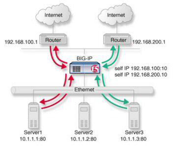
ISP load balancing

ISP load balancing

Creating a load balancing pool

Ensure that at least one virtual server exists in the configuration before you start to create a load balancing pool.
Create a pool of systems with Access Policy Manager to which the system can load balance global traffic.
  1. On the Main tab, click DNS > GSLB > Pools .
    The Pool List screen opens.
  2. Click Create.
    The New Pool screen opens.
  3. In the General Properties area, in the Name field, type a name for the pool.
    Names must begin with a letter, and can contain only letters, numbers, and the underscore (_) character.
    Important: The pool name is limited to 63 characters.
  4. From the Type list, depending on the type of the system (IPv4 or IPv6), select either an A or AAAA pool type.
  5. In the Configuration area, for the Health Monitors setting, in the Available list, select a monitor type, and move the monitor to the Selected list.
    Tip: Hold the Shift or Ctrl key to select more than one monitor at a time.
  6. In the Members area, for the Load Balancing Method settings, select a method that uses virtual server score:
    • VS Score - If you select this method, load balancing decisions are based on the virtual server score only.
    • Quality of Service - If you select this method, you must configure weights for up to nine measures of service, including VS Score. Virtual server score then factors into the load balancing decision at the weight you specify.
  7. For the Member List setting, add virtual servers as members of this load balancing pool.
    The system evaluates the virtual servers (pool members) in the order in which they are listed. A virtual server can belong to more than one pool.
    1. Select a virtual server from the Virtual Server list.
    2. Click Add.
  8. Click Finished.

Creating a virtual server for inbound content server traffic

You must create a virtual server to load balance inbound connections. The default pool that you assign as a resource in this procedure is the pool of internal servers.
  1. On the Main tab, click Local Traffic > Virtual Servers .
    The Virtual Server List screen opens.
  2. Click the Create button.
    The New Virtual Server screen opens.
  3. In the Name field, type a unique name for the virtual server.
  4. In the Destination Address field, type the IP address in CIDR format.
    The supported format is address/prefix, where the prefix length is in bits. For example, an IPv4 address/prefix is 10.0.0.1 or 10.0.0.0/24, and an IPv6 address/prefix is ffe1::0020/64 or 2001:ed8:77b5:2:10:10:100:42/64. When you use an IPv4 address without specifying a prefix, the BIG-IP system automatically uses a /32 prefix.
    Note: The IP address you type must be available and not in the loopback network.
  5. In the Service Port field:
    • If you want to specify a single service port or all ports, confirm that the Port button is selected, and type or select a service port.
    • If you want to specify multiple ports other than all ports, select the Port List button, and confirm that the port list that you previously created appears in the box.
  6. If the traffic to be load balanced is of a certain type, select the profile type that matches the connection type.
    To load balance HTTP traffic, locate the HTTP Profile setting and select http.
  7. In the Resources area of the screen, from the Default Pool list, select the relevant pool name.
  8. Click Finished.
The virtual server is configured to load balance inbound connections to the servers.

Creating a virtual server for outbound traffic for routers

You must create a virtual server to load balance outbound connections. The default pool that you assign as a resource in this procedure is the pool of routers.
  1. On the Main tab, click Local Traffic > Virtual Servers .
    The Virtual Server List screen opens.
  2. Click the Create button.
    The New Virtual Server screen opens.
  3. In the Name field, type a unique name for the virtual server.
  4. In the Destination Address field, type the IP address in CIDR format.
    The supported format is address/prefix, where the prefix length is in bits. For example, an IPv4 address/prefix is 10.0.0.1 or 10.0.0.0/24, and an IPv6 address/prefix is ffe1::0020/64 or 2001:ed8:77b5:2:10:10:100:42/64. When you use an IPv4 address without specifying a prefix, the BIG-IP system automatically uses a /32 prefix.
    Note: The IP address you type must be available and not in the loopback network.
  5. In the Resources area of the screen, from the Default Pool list, select the relevant pool name.
  6. Click Finished.
The virtual server is configured to load balance outbound connections to the routers.

Creating self IP addresses an external VLAN

You must assign two self IP addresses to the external VLAN.
  1. On the Main tab, click Network > Self IPs .
  2. Click Create.
    The New Self IP screen opens.
  3. In the IP Address field, type an IP address.
    This IP address should represent the network of the router.
    The system accepts IPv4 and IPv6 addresses.
  4. In the Netmask field, type the network mask for the specified IP address.

    For example, you can type 255.255.255.0.

  5. Select External from the VLAN list.
  6. Click Repeat.
  7. In the IP Address field, type an IPv4 or IPv6 address.
    This IP address should represent the address space of the VLAN that you specify with the VLAN/Tunnel setting.
  8. Click Finished.
    The screen refreshes, and displays the new self IP address.
The self IP address is assigned to the external VLAN.

Enabling SNAT automap for internal and external VLANs

You can configure SNAT automapping on the BIG-IP system for internal and external VLANs.
  1. On the Main tab, click Local Traffic > Address Translation .
    The SNAT List screen displays a list of existing SNATs.
  2. Click Create.
  3. Name the new SNAT.
  4. From the Translation list, select Automap.
  5. For the VLAN / Tunnel List setting, in the Available list, select external and internal, and using the Move button, transfer the VLANs to the Selected list.
  6. Click the Finished button.
SNAT automapping on the BIG-IP system is configured for internal and external VLANs.