Applies To:
Show Versions
BIG-IP LTM
- 14.1.2, 14.1.0
Configuring SIP Load Balancing
Overview: Configuring a SIP proxy
You can use the BIG-IP® system as a Session Initiation Protocol (SIP) proxy. When the BIG-IP system is placed between your SIP routers, session border controllers, and soft switches, you can configure the system to route and load balance SIP messages across the servers on your SIP network.
This graphic illustrates the relationships of the configuration objects that you must configure on the BIG-IP system.
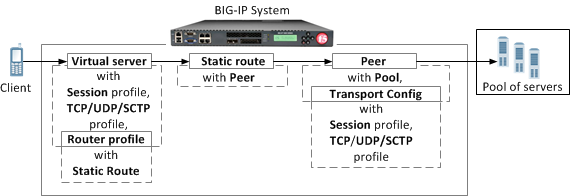
SIP proxy configuration objects
Task summary
About managing MRF SIP session traffic
Through the SIP Session Profile, you can use Message Routing Framework (MRF) to manage SIP traffic across pool members by means of configuring and using Via headers. When you configure Via headers to manage SIP traffic, dependencies between settings apply, enabling you to steer traffic and control requests and responses, as necessary.
Example: SIP session traffic scenario 1 (default)
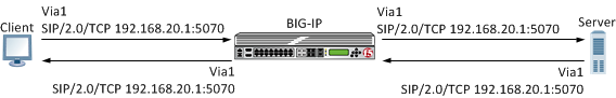
In SIP session traffic scenario 1 (default), the BIG-IP system receives a request with a Via1 header from a client, and inserts a Via2 header into the request before forwarding the request to the server. When the server provides a response, the BIG-IP system removes the Via2 header from the response, before forwarding the response to the client. If the originating connection no longer exists, the Via2 header that BIG-IP system inserted is no longer available; consequently, the BIG-IP system uses the Via1 header, forwarding the message to the client IP address and port specified by that Via header.
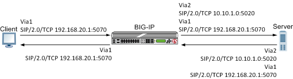
An example of SIP session traffic scenario 1 (default)
When configuring this scenario, the following SIP Session Profile settings apply.
| SIP Session Profile control | Setting or value |
|---|---|
| Honor Via | Enabled |
| Do Not Connect Back | Disabled |
| Insert Via Header | Enabled |
| Custom Via | Not applicable |
Example: SIP session traffic scenario 2
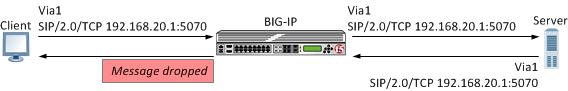
In SIP session traffic scenario 2, the BIG-IP system receives a request with a Via1 header from a client, and inserts a Via2 header into the request before forwarding the request to the server. When the server provides a response, the BIG-IP system removes the Via2 header from the response, before forwarding the response to the client. When the originating connection no longer exists, then the BIG-IP system drops the response message and increments the statistic for Messages failed due to connection dropped.
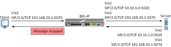
An example of SIP session traffic scenario 2
When configuring this scenario, the following SIP Session Profile settings apply.
| SIP Session Profile control | Setting or value |
|---|---|
| Honor Via | Enabled |
| Do Not Connect Back | Enabled |
| Insert Via Header | Enabled |
| Custom Via | Not applicable |
Example: SIP session traffic scenario 3
In SIP session traffic scenario 3, the BIG-IP system receives a request with a Via1 header from a client, and inserts a Via2 header into the request before forwarding the request to the server. When the server provides a response, the BIG-IP system removes the Via2 header from the response, before forwarding the response to the client. If the originating connection no longer exists, then the Via header that BIG-IP system inserted is no longer available; consequently, the BIG-IP system uses the next available Via header, but, because the Honor Via setting is Disabled, the BIG-IP system does not forward the message to the client IP address and port specified by that Via header.
An example of SIP session traffic scenario 3
When configuring this scenario, the following SIP Session Profile settings apply.
| SIP Session Profile control | Setting or value |
|---|---|
| Honor Via | Disabled |
| Do Not Connect Back | Disabled |
| Insert Via Header | Enabled |
| Custom Via | Not applicable |
Example: SIP session traffic scenario 4
In SIP session traffic scenario 4, the BIG-IP system receives a request with a Via1 header from a client, and inserts a Via2 header into the request before forwarding the request to the server. When the server provides a response, the response from the BIG-IP to the client must be managed by means of an iRule, for example, MR::message nexthop TMM:flow_id or MR::message route virtual vs_name host ip:port.
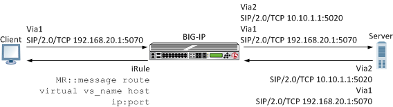
An example of SIP session traffic scenario 4
When configuring this scenario, the following SIP Session Profile settings apply.
| SIP Session Profile control | Setting or value |
|---|---|
| Honor Via | Not applicable |
| Do Not Connect Back | Not applicable |
| Insert Via Header | Enabled |
| Custom Via | Custom Via header value, for example: SIP/2.0/TCP www.siterequest.com:4343 or SIP/2.0/SCTP 10.10.4.32 |
Example: SIP session traffic scenario 5
In SIP session traffic scenario 5, the BIG-IP system receives a request with a Via1 header from a client, but does not insert a Via header into the request before forwarding the request to the server. When the server provides a response, the BIG-IP system uses the client Via1 header in the response to forward the message to the client IP address and port specified by that Via header.
An example of SIP session traffic scenario 5
When configuring this scenario, the following SIP Session Profile settings apply.
| SIP Session Profile control | Setting or value |
|---|---|
| Honor Via | Enabled |
| Do Not Connect Back | Not applicable |
| Insert Via Header | Disabled |
| Custom Via | Not applicable |
Example: SIP session traffic scenario 6
In SIP session traffic scenario 6, the BIG-IP system receives a request with a Via1 header from a client, but does not insert a Via header into the request before forwarding the request to the server. Instead, the BIG-IP system uses the Via1 header specified in the request. When the server provides a response, the BIG-IP system uses the Via1 header in the response, but does not forward the message to the client IP address and port specified by that Via header.
An example of SIP session traffic scenario 6
When configuring this scenario, the following SIP Session Profile settings apply.
| SIP Session Profile control | Setting or value |
|---|---|
| Honor Via | Disabled |
| Do Not Connect Back | Not applicable |
| Insert Via Header | Disabled |
| Custom Via | Not applicable |
Configuration objects required for a SIP proxy
This table names and describes the objects necessary to configure the BIG-IP system as a SIP proxy.
| Configuration Objects | Description |
|---|---|
| Session Profile | Defines how BIG-IP processes SIP messages, including the data used to persist SIP connections. |
| Transport config | Defines how BIG-IP connects with the servers on your SIP network. |
| Pool | Defines how BIG-IP load balances connections across a group of servers. |
| Peer | Defines how BIG-IP connects with the servers on your network and to which servers the system routes and load balances SIP messages. |
| Static route | Defines how BIG-IP routes SIP messages. |
| Router profile | Defines an instance of a SIP router. |
| Virtual Server | Defines the destinations in your network, including the servers that process incoming SIP requests and the pool members that process connections between BIG-IP and your SIP network. |
Task summary for configuring SIP load balancing
Complete these tasks to configure SIP message routing on a system.
Creating a SIP session profile
Creating a transport config
Implementing Low-Latency Electronic Trading with FIX load balancing
Creating a peer
Creating a static route
Creating a SIP router profile
Creating a virtual server to handle SIP client requests
Configuration objects required for a SIP proxy
This table names and describes the objects necessary to configure the BIG-IP system as a SIP proxy.
| Configuration Objects | Description |
|---|---|
| Session Profile | Defines how BIG-IP processes SIP messages, including the data used to persist SIP connections. |
| Transport config | Defines how BIG-IP connects with the servers on your SIP network. |
| Pool | Defines how BIG-IP load balances connections across a group of servers. |
| Peer | Defines how BIG-IP connects with the servers on your network and to which servers the system routes and load balances SIP messages. |
| Static route | Defines how BIG-IP routes SIP messages. |
| Router profile | Defines an instance of a SIP router. |
| Virtual Server | Defines the destinations in your network, including the servers that process incoming SIP requests and the pool members that process connections between BIG-IP and your SIP network. |
About checking pool member health
You can configure the BIG-IP system to monitor pool member health using a SIP monitor. Use a SIP monitor to check the health of a host with an active SIP session. The SIP monitor also monitors a SIP connection independent of a specific SIP session and marks a host that had been marked down, but is online again, as available.
Task summary
Perform these tasks to configure health monitors and apply the monitors to a pool:
Creating a SIP monitor
Adding a health monitor to a pool
About viewing SIP session and router statistics
You can view statistics for SIP sessions and routes.


