Applies To:
Show Versions
BIG-IP AAM
- 14.0.1, 14.0.0
BIG-IP APM
- 14.0.1, 14.0.0
BIG-IP Analytics
- 14.0.1, 14.0.0
BIG-IP Link Controller
- 14.0.1, 14.0.0
BIG-IP LTM
- 14.0.1, 14.0.0
BIG-IP PEM
- 14.0.1, 14.0.0
BIG-IP AFM
- 14.0.1, 14.0.0
BIG-IP DNS
- 14.0.1, 14.0.0
BIG-IP ASM
- 14.0.1, 14.0.0
VLANs, VLAN Groups, and VXLAN
About VLANs
A VLAN is a logical subset of hosts on a local area network (LAN) that operate in the same IP address space. Grouping hosts together in a VLAN has distinct advantages. For example, with VLANs, you can:
- Reduce the size of broadcast domains, thereby enhancing overall network performance.
- Reduce system and network maintenance tasks substantially. Functionally-related hosts no longer need to physically reside together to achieve optimal network performance.
- Enhance security on your network by segmenting hosts that must transmit sensitive data.
You can create a VLAN and associate physical interfaces with that VLAN. In this way, any host that sends traffic to a BIG-IP® system interface is logically a member of the VLAN or VLANs to which that interface belongs.
Default VLAN configuration
By default, the BIG-IP® system includes VLANs named internal and external. When you initially ran the Setup utility, you assigned the following to each of these VLANs:
- A static and a floating self IP address
- A VLAN tag
- One or more BIG-IP system interfaces
A typical VLAN configuration is one in which the system has the two VLANs external and internal, and one or more BIG-IP system interfaces assigned to each VLAN. You then create a virtual server, and associate a default load balancing pool with that virtual server. This figure shows a typical configuration using the default VLANs external and internal.
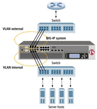
A typical configuration using the default VLANs
About VLANs and interfaces
VLANs are directly associated with the physical interfaces on the BIG-IP® system.
Interface assignments
For each VLAN that you create, you must assign one or more BIG-IP® system interfaces to that VLAN. When you assign an interface to a VLAN, you indirectly control the hosts from which the BIG-IP system interface sends or receives messages.
For example, if you assign interface 1.11 to VLAN A, and you then associate VLAN A with a virtual server, then the virtual server sends its outgoing traffic through interface 1.11, to a destination host in VLAN A. Similarly, when a destination host sends a message to the BIG-IP system, the host’s VLAN membership determines the BIG-IP system interface that should receive the incoming traffic.
Each VLAN has a MAC address. The MAC address of a VLAN is the same MAC address of the lowest-numbered interface assigned to that VLAN.
About tagged interfaces
You can create a VLAN and assign interfaces to the VLAN as single- or double-tagged interfaces. When you assign interfaces as tagged interfaces, you can associate multiple VLANs with those interfaces.
A VLAN tag is a unique ID number that you assign to a VLAN, to identify the VLAN to which each packet belongs. If you do not explicitly assign a tag to a VLAN, the BIG-IP® system assigns a tag automatically. The value of a VLAN tag can be between 1 and 4094. Once you or the BIG-IP system assigns a tag to a VLAN, any message sent from a host in that VLAN includes this VLAN tag as a header in the message.
About single tagging
This figure shows the difference between using three untagged interfaces (where each interface must belong to a separate VLAN) versus one single-tagged interface (which belongs to multiple VLANs).
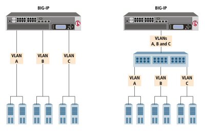
Solutions using untagged (left) and single-tagged interfaces (right)
The configuration on the left shows a BIG-IP system with three internal interfaces, each a separate, untagged interface. This is a typical solution for supporting three separate customer sites. In this scenario, each interface can accept traffic only from its own VLAN.
Conversely, the configuration on the right shows a BIG-IP system with one internal interface and an external switch. The switch places the internal interface on three separate VLANs. The interface is configured on each VLAN as a single-tagged interface. In this way, the single interface becomes a tagged member of all three VLANs, and accepts traffic from all three. The configuration on the right is the functional equivalent of the configuration of the left.
About double tagging
For BIG-IP systems with ePVA hardware support, the system includes support for the IEEE 802.1QinQ standard. Known informally as Q-in-Q or double tagging, this standard provides a way for you to insert multiple VLAN tags into a single frame. This allows you to encapsulate single-tagged traffic from disparate customers with only one tag.
Double tagging expands the number of possible VLAN IDs in a network. With double tagging, the theoretical limitation in the number of VLAN IDs expands from 4096 to 4096*4096.
When you implement double tagging, you specify an inner tag that encapsulates all of the single-tagged traffic. You then designate all other tags as outer tags, or customer tags (C-tags), which serve to identify and segregate the traffic from those customers.
A common use case is one in which an internet service provider creates a single VLAN within which multiple customers can retain their own VLANs without regard for overlapping VLAN IDs. Moreover, you can use double-tagged VLANs within route domains or vCMP guests. In the latter case, vCMP host administrators can create double-tagged VLANs and assign the VLANs to guests, just as they do with single-tagged VLANs. For a vCMP guest running an older version of the BIG-IP software, double-tagged VLANs are not available for assignment to the guest.
VLAN association with a self IP address
Every VLAN must have a static self IP address associated with it. The self IP address of a VLAN represents an address space, that is, the range of IP addresses pertaining to the hosts in that VLAN. When you ran the Setup utility earlier, you assigned one static self IP address to the VLAN external, and one static self IP address to the VLAN internal. When sending a request to a destination server, the BIG-IP system can use these self IP addresses to determine the specific VLAN that contains the destination server.
The self IP address with which you associate a VLAN should represent an address space that includes the IP addresses of the hosts that the VLAN contains. For example, if the address of one host is 11.0.0.1 and the address of the other host is 11.0.0.2, you could associate the VLAN with a self IP address of 11.0.0.100, with a netmask of 255.255.255.0.
VLAN assignment to route domains
If you explicitly create route domains, you should consider the following facts:
- You can assign VLANs (and VLAN groups) to route domain objects that you create. Traffic pertaining to that route domain uses those assigned VLANs.
- During BIG-IP® system installation, the system automatically creates a default route domain, with an ID of 0. Route domain 0 has two VLANs assigned to it, VLAN internal and VLAN external.
- If you create one or more VLANs in an administrative partition other than Common, but do not create a route domain in that partition, then the VLANs you create in that partition are automatically assigned to route domain 0.
Maintaining the L2 forwarding table
Layer 2 forwarding is the means by which frames are exchanged directly between hosts, with no IP routing required. This is accomplished using a simple forwarding table for each VLAN. The L2 forwarding table is a list that shows, for each host in the VLAN, the MAC address of the host, along with the interface that the BIG-IP® system needs for sending frames to that host. The intent of the L2 forwarding table is to help the BIG-IP system determine the correct interface for sending frames, when the system determines that no routing is required.
The format of an entry in the L2 forwarding table is:
<MAC address> -> <if>
For example, an entry for a host in the VLAN might look like this:
00:a0:c9:9e:1e:2f -> 2.1
The BIG-IP system learns the interfaces that correspond to various MAC entries as frames pass through the system, and automatically adds entries to the table accordingly. These entries are known as dynamic entries. You can also add entries to the table manually, and these are known as static entries. Entering static entries is useful if you have network devices that do not advertise their MAC addresses. The system does not automatically update static entries.
The BIG-IP system does not always need to use the L2 forwarding table to find an interface for frame transmission. For instance, if a VLAN has only one interface assigned to it, then the BIG-IP system automatically uses that interface.
Occasionally, the L2 forwarding table does not include an entry for the destination MAC address and its corresponding BIG-IP system interface. In this case, the BIG-IP system floods the frame through all interfaces associated with the VLAN, until a reply creates an entry in the L2 forwarding table.
Additional VLAN configuration options
There are a number of settings that you can configure for a VLAN.
Source checking
When you enable source checking, the BIG-IP® system verifies that the return path for an initial packet is through the same VLAN from which the packet originated. Note that the system only enables source checking if the global setting Auto Last Hop is disabled.
Maximum transmission units
The value that you configure for the maximum transmission unit, or MTU, is the largest size that the BIG-IP® system allows for an IP datagram passing through a BIG-IP system interface. By default, the BIG-IP system uses the standard Ethernet frame size of 1518 bytes (1522 bytes if VLAN tagging is used), with a corresponding MTU value of 1500 bytes for a VLAN.
One reason for changing the value of the MTU setting is when your BIG-IP platform supports jumbo frames. A jumbo frame is an Ethernet frame with more than 1500 bytes, and fewer than 9000 bytes, of payload.
If your BIG-IP platform does not support jumbo frames and a VLAN receives a jumbo frame, the system discards the frame.
VLAN-based fail-safe
VLAN fail-safe is a feature you enable when you want to base redundant-system failover on VLAN-related events. To configure VLAN fail-safe, you specify a timeout value and the action that you want the system to take when the timeout period expires.
Auto last hop
When you create a VLAN, you can designate the VLAN as the last hop for TMM traffic.
CMP hash
The CMP Hash setting allows all connections from a client system to use the same set of TMMs. This improves system performance. In configuring the CMP Hash value, you can choose the traffic disaggregation criteria for the VLAN, either source IP address, destination IP address, or TCP/UDP source/destination ports. The default value uses TCP/UDP source/destination ports. Note that the CMP Hash setting appears only on the properties screen for an existing VLAN.
DAG round robin
You can use the DAG Round Robin setting on a VLAN to prevent stateless traffic from overloading a few TMM instances, a condition that can disable an entire BIG-IP system. When enabled, this setting causes the BIG-IP system to load balance the traffic among TMMs evenly, instead of using a static hash. Stateless traffic in this case includes non-IP Layer 2 traffic, ICMP, some UDP protocols, and so on. This setting is disabled by default.
This feature is particularly useful for firewall and Domain Name System (DNS) traffic. For example, this feature prevents certain types of DDoS attacks, such as an ICMP DDoS attack that can overload the system by sending the same packets repeatedly to a specific subset of TMMs.
Specifying port numbers
When you enable the DAG Round Robin feature on a VLAN, you must also configure a bigdb variable that specifies the relevant destination ports.
DAG tunnel
You can use the DAG Tunnel setting on a VLAN to enable hardware-based disaggregation. This defines how the disaggregator (DAG) processes received packets that are encapsulated using one of the supported tunneling protocols (such as, NVGRE, VXLAN, EtherIP, IPIP).
There are two options for DAG tunnel:
- Inner
- Disaggregates encapsulated packets based on the inner headers. Using the inner headers typically provides more information to the DAG which allows for a better distribution of packets across TMM instances. If you select a value of Inner, you must also configure a bigdb variable to specify a port number before any associated tunnels can use the inner headers.
- Outer
- Uses the outer headers of encapsulated packets without inspecting the inner headers. This is the default value.
Specifying a port number
When you enable the DAG tunnel feature on a VLAN, you must also configure a bigdb variable that specifies a port number so that associated tunnels can disaggregate based on the inner header of a packet.
Configuring DAG tunnel using tmsh
You can use the Traffic Management Shell (tmsh) to configure the DAG tunnel feature on a VLAN. The default value is outer.
About sFlow polling intervals and sampling rates
You can change the sFlow settings for a specific VLAN when you want the traffic flowing through the VLAN to be sampled at a different rate than the global sFlow settings on the BIG-IP® system.
Creating a VLAN
About VLAN groups
A VLAN group is a logical container that includes two or more distinct VLANs. VLAN groups are intended for load balancing traffic in a Layer 2 network, when you want to minimize the reconfiguration of hosts on that network. This figure shows an example of a VLAN group.
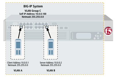
Example of a VLAN group
A VLAN group also ensures that the BIG-IP® system can process traffic successfully between a client and server when the two hosts reside in the same address space. Without a VLAN group, when the client and server both reside in the same address space, the client request goes through the virtual server, but instead of sending its response back through the virtual server, the server attempts to send its response directly to the client, bypassing the virtual server altogether. As a result, the client cannot receive the response, because the client expects the address of the response to be the virtual server IP address, not the server IP address.
When you create a VLAN group, the two existing VLANs become child VLANs of the VLAN group.
VLAN groups reside in administrative partitions. To create a VLAN group, you must first set the current partition to the partition in which you want the VLAN group to reside.
About VLAN group names
When creating a VLAN group, you must assign it a unique name. Once you have finished creating the VLAN group, the VLAN group name appears in the list of existing VLANs groups.
VLAN group ID
A VLAN group ID is a tag for the VLAN group. Every VLAN group needs a unique ID number. If you do not specify an ID for the VLAN group, the BIG-IP® system automatically assigns one. The value of a VLAN group ID can be between 1 and 4094.
About untagged interfaces
You can create a VLAN and assign interfaces to the VLAN as untagged interfaces. When you assign interfaces as untagged interfaces, you cannot associate other VLANs with those interfaces. This limits the interface to accepting traffic only from that VLAN, instead of from multiple VLANs. If you want to give an interface the ability to accept and receive traffic for multiple VLANs, you add the same interface to each VLAN as a tagged interface.
VLAN group association with a self IP address
A VLAN group is used to bridge traffic between two or more VLANs. All member VLANs contain hosts that reside in the same IP address space (for example, 10.0.0.0/24). When using a VLAN group, you normally only need to assign a self IP address to the VLAN group itself (that is, a member VLAN does not require a self IP address of its own). The self IP address that you associate with a VLAN group should represent the IP address space covered by the VLAN group. For example, if some of the hosts in one member VLAN use IP addresses 10.0.0.1 and 10.0.0.2, and some of the hosts in another member VLAN use IP addresses 10.0.0.201 and 10.0.0.202, you could then associate the VLAN group with a self IP address of 10.0.0.100, with a netmask of 255.255.255.0.
About transparency mode
The BIG-IP® system is capable of processing traffic using a combination of Layer 2 and Layer 3 forwarding, that is, switching and IP routing. When you set the transparency mode, you specify the type of forwarding that the BIG-IP system performs when forwarding a message to a host in a VLAN. The default setting is Translucent, which means that the BIG-IP system uses a mix of Layer 2 and Layer 3 processing. The allowed values are:
- Opaque
- A proxy ARP with Layer 3 forwarding.
- Translucent
- Layer 2 forwarding with a locally-unique bit, toggled in ARP response across VLANs. This is the default setting.
- Transparent
- Layer 2 forwarding with the original MAC address of the remote system preserved across VLANs.
About traffic bridging
When you enable the traffic bridging option, you are instructing the VLAN group to forward all non-IP traffic. Note that IP traffic is bridged by default. The default value for this setting is disabled (unchecked).
About traffic bridging with standby units
When enabled, the Bridge in Standby setting ensures that the VLAN group can forward packets when the system is the standby device of a redundant system configuration. Note that this setting applies to non-IP and non-ARP frames only, such as Bridge Protocol Data Units (BPDUs).
This setting is designed for deployments in which the VLAN group is defined on a redundant system. You can use the Bridge in Standby setting in transparent or translucent modes, or in opaque mode when the global variable Failover.Standby.LinkDownTime is set to 0.
About migration keepalive frames
The Migration Keepalive setting for a VLAN group, when enabled, instructs the BIG-IP system to send keepalive frames (that is, TCP keepalives and empty UDP packets, depending on the connection type) when a node is moved from one VLAN group member to another VLAN group member for all existing BIG-IP connections to that node.
About host exclusion from proxy ARP forwarding
A host in a VLAN cannot normally communicate to a host in another VLAN. This rule applies to ARP requests as well. However, if you put the VLANs into a single VLAN group, the BIG-IP system can perform a proxied ARP request.
A proxied ARP request is an ARP request that the BIG-IP system can send, on behalf of a host in a VLAN, to hosts in another VLAN. A proxied ARP request requires that both VLANs belong to the same VLAN group.
In some cases, you might not want a host to forward proxied ARP requests to a specific host, or to other hosts in the configuration. To exclude specific hosts from receiving forwarded proxied ARP requests, you use the BIG-IP Configuration utility and specify the IP addresses that you want to exclude.
Creating a VLAN group
About bridging VLAN and VXLAN networks
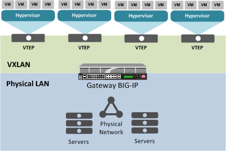
You can configure Virtual eXtended LAN (VXLAN) on a BIG-IP® system to enable a physical VLAN to communicate with virtual machines (VMs) in a virtual network.
The VXLAN gateway
When you configure a BIG-IP system as an L2 VXLAN gateway, the BIG-IP system joins the configured multicast group, and can forward both unicast and multicast or broadcast frames on the virtual network. The BIG-IP system learns about MAC address and VTEP associations dynamically, thus avoiding unnecessary transmission of multicast traffic.
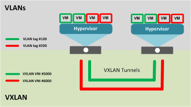
Multiple VXLAN tunnels
About VXLAN multicast configuration
In a VMware vSphere 5.1 environment, you can configure VXLAN without knowing all the remote tunnel endpoints. The BIG-IP® system uses multicast flooding to learn unknown and broadcast frames. VXLAN can extend the virtual network across a set of hypervisors, providing L2 connectivity among the hosted virtual machines (VMs). Each hypervisor represents a VXLAN tunnel endpoint (VTEP). In this environment, you can configure a BIG-IP system as an L2 VXLAN gateway device to terminate the VXLAN tunnel and forward traffic to and from a physical network.


