Applies To:
Show Versions
BIG-IP LTM
- 12.1.6, 12.1.5, 12.1.4, 12.1.3, 12.1.2, 12.1.1, 12.1.0
Overview: Using the FTP ALG Profile to Transfer Files
The File Transfer Protocol (FTP) application layer gateway (ALG) profile enables you to transfer files between a client and server. The FTP ALG profile supports both active and passive modes, where data connections are initiated either from an FTP server (active mode) or from a client (passive mode). You can transfer files using the FTP protocol by configuring an LSN pool, configuring an FTP profile, and then assigning the LSN pool and FTP profile to a virtual server. The FTP protocol is described in RFC 959.
Task summary
About the FTP profile
The File Transfer Protocol (FTP) profile enables you to transfer files between a client and server, using FTP connections over TCP. The FTP application layer gateway (ALG) supports the FTP protocol's active and passive modes, where data connections are initiated either from an FTP server (active mode) or from a client (passive mode).
You can configure the FTP profile settings, as needed, to ensure compatibility between IPv4 and IPv6 clients and servers, to enable the FTP data channel to inherit the TCP profile used by the FTP control channel, and to use a port other than the default port (20). Additionally, when used with Application Security Manager™ (ASM™), this profile enables the BIG-IP® system to inspect FTP traffic for security vulnerabilities by using an FTP security profile.
FTP Control Channels
Once established, the FTP control channel remains open throughout the FTP session. The FTP control channel and the FTP data channel must both originate from the same IP address.
FTP Data Channels
In active mode, the FTP server initiates data connections. A client informs the server as to what port the client is listening on, and the server connects to the client by using that port.
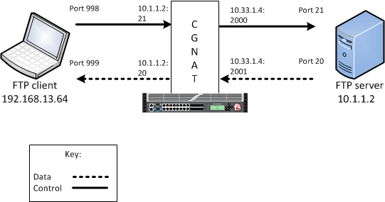
An example FTP active mode configuration
In this example, an LSN pool is configured with a translation IP address and prefix length of 10.33.1.0/24. The virtual server is configured with an FTP control port using a wildcard address and a specific port: 0.0.0.0:21. The FTP data port is configured to use port 20. The configured translation mode uses the values of the respective port range.
| Translation mode | Port range |
|---|---|
| NAPT | 2000-3000 |
| DNAT | 2000-2200 |
| PBA | 2000-2150 |
In passive mode, the FTP client initiates data connections. The FTP server informs the client as to what port the server is listening on, and the client connects to the server by using that port.
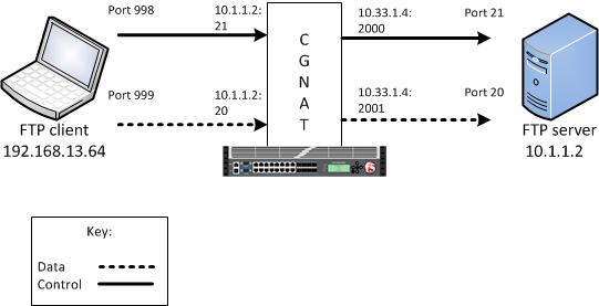
An example FTP passive mode configuration
In this example, an LSN pool is configured with a translation IP address and prefix length of 10.33.1.0/24. The virtual server is configured with an FTP control port using a wildcard address and a specific port: 0.0.0.0:21. The FTP data port is configured to use port 20. In this example, the configured translation mode uses the values of the respective port range.
| Translation mode | Port range |
|---|---|
| NAPT | 2000-3000 |
| DNAT | 2000-2200 |
| PBA | 2000-2150 |
Creating an LSN pool
Creating an FTP profile
Configuring a CGNAT iRule
Creating a virtual server using an FTP ALG profile
Creating an FTP ALG logging profile
Configuring an FTP ALG profile
Overview: Using the SIP ALG Profile for Multimedia Sessions
The Session Initiation Protocol (SIP) application layer gateway (ALG) profile enables you to manage peer-to-peer connections through a CGNAT, permitting a client on an external network to initiate and establish a multimedia session with a user on an internal network. You can enable SIP multimedia sessions by configuring an LSN pool, configuring a SIP profile, and then assigning the LSN pool and SIP profile to a virtual server. The SIP protocol is described in RFC 3261.
Task summary
About the SIP ALG profile
The Session Initiation Protocol (SIP) profile establishes connections over TCP, UDP, and SCTP through a CGNAT. It creates the connections by establishing flows for multimedia traffic, and by translating IP addresses included in SIP messages into external IP addresses. As a result, these can be reached by means of a public network. Once a call is established, the SIP ALG creates flows for multimedia traffic (as determined by the advertised address and port combinations on either side of a call), and tears down the flow when the call ends.
- A maximum message size
- Closed connection when a BYE transaction completes
- Use of SIP dialog information
- High-speed logging (HSL) security checking
- Association of a SIP virtual server-profile pairing with a SIP proxy functional group
- Via headers
- Record-Route headers
- Real-Time Transport (RTP) proxy style for media relaying
- Timing for dialog establishment or SIP session tunnel
- Definition of maximum media sessions, sessions per registration, or registrations
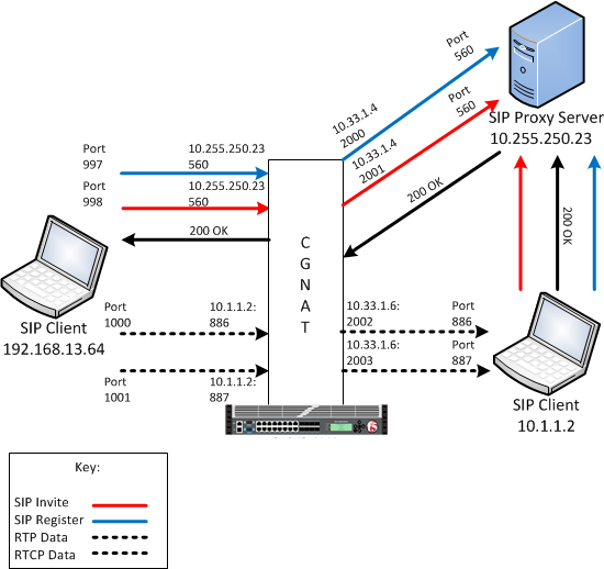
An example SIP ALG configuration
In this example, an LSN pool is configured with a translation IP address and prefix length of 10.33.1.0/24. The virtual server is configured with a register and invite port that use a wildcard destination address and a specific port: 0.0.0.0:560. The SIP RTP data port is configured to use port 886 and the RTCP data port is configured to use port 887. The configured translation mode uses the values of the respective port range.
| Translation mode | Port range |
|---|---|
| NAPT | 2000-3000 |
| DNAT | 2000-2200 |
| PBA | 2000-2150 |
Creating an LSN pool
Creating a SIP profile
Creating a virtual server using a SIP ALG profile
Creating an empty LSN pool
Creating a virtual server using a SIP ALG profile and empty LSN pool
Creating an SIP ALG logging profile
Configuring an SIP ALG profile
Overview: Using the RTSP ALG Profile to Stream Media
The Real Time Streaming Protocol (RTSP) application layer gateway (ALG) profile enables you to establish streaming multimedia sessions between a client and a server. You can stream multimedia sessions by configuring an LSN pool, configuring an RTSP profile, and then assigning the LSN pool and RTSP profile to a virtual server. The RTSP protocol is described in RFC 2326.
Task summary
About the RTSP ALG profile
The Real Time Streaming Protocol (RTSP) profile enables you to stream multimedia content between a client and server, using RTSP connections over TCP. The RTSP application layer group (ALG) supports the RTSP protocol's control channel to an RTSP server, through which the client requests a file for the server to stream (and controls the streaming of that file with commands like play or pause). The client can request streaming over UDP and provide two listening ports for the server response. The RTSP server responds with a Real-Time Transport Protocol (RTP) data channel port, to stream the requested file, and a Real-Time Control Protocol (RTCP) control channel port, which provides a stream description and status.
You can configure the RTSP profile settings, as needed.
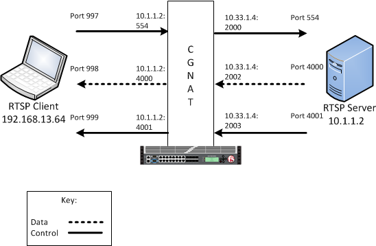
An example RTSP ALG configuration
In this example, an LSN pool is configured with a translation IP address and prefix length of 10.33.1.0/24. The virtual server is configured with an RTSP control port using a wildcard address and a specific port: 0.0.0.0:554. The configured translation mode uses the values of the respective port range.
| Translation mode | Port range |
|---|---|
| NAPT | 2000-3000 |
| DNAT | 2000-2200 |
| PBA | 2000-2150 |
Creating an LSN pool
Creating an RTSP profile
Configuring a CGNAT iRule
Creating a virtual server using an RTSP ALG profile
Creating an RTSP ALG logging profile
Configuring an RTSP ALG profile
Overview: Using the PPTP ALG profile to create a VPN tunnel
The point-to-point tunneling protocol (PPTP) profile enables you to configure the BIG-IP® system to support a secure virtual private network (VPN) tunnel that forwards PPTP control and data connections. You can create a secure VPN tunnel by configuring a PPTP Profile, and then assigning the PPTP profile to a virtual server. The PPTP protocol is described in RFC 2637.
Task summary
About the PPTP ALG profile
The point-to-point tunneling protocol (PPTP) profile enables you to configure the BIG-IP® system to support a secure virtual private network (VPN) tunnel. A PPTP application layer gateway (ALG) forwards PPTP client (also known as PPTP Access Concentrator [PAC]) control and data connections through the BIG-IP system to PPTP servers (also known as PPTP Network Servers [PNSs]), while providing source address translation that allows multiple clients to share a single translation address.
The PPTP profile defines a Transmission Control Protocol (TCP) control connection and a data channel through a PPTP Generic Routing Encapsulation (GRE) tunnel, which manages the PPTP tunnels through CGNAT for NAT44 and DS-Lite, as well as all translation modes, including Network Address Port Translation (NAPT), Deterministic, and Port Block Allocation (PBA) modes.
PPTP control channels
The BIG-IP system proxies PPTP control channels as normal TCP connections. The PPTP profile translates outbound control messages, which contain Call Identification numbers (Call IDs) that match the port that is selected on the outbound side. Subsequently, for inbound control messages containing translated Call IDs, the BIG-IP system restores the original client Call ID. You can use a packet tracer to observe this translation on the subscriber side or on the Internet side. You can also use iRules® to evaluate and manage any headers in the PPTP control channel.
PPTP GRE data channels
The BIG-IP system manages the translation for PPTP GRE data channels in a manner similar to that of control channels. The BIG-IP system replaces the translated Call ID from the Key field of the GRE header with the inbound client's Call ID. You can use a packet tracer to observe this translation, as well.
An example PPTP ALG configuration
Log messages
The PPTP profile enables you to configure Log Settings, specifically the Publisher Name setting, which logs the name of the log publisher, and the Include Destination IP setting, which logs the host IP address of the PPTP server, for each call establishment, call failure, and call teardown.
PPTP profile log example
This topic includes examples of the elements that comprise a typical log entry.
Description of PPTP log messages
PPTP log messages include several elements of interest. The following examples describe typical log messages.
"Mar 1 18:46:11:PPTP CALL-REQUEST id;0 from;10.10.10.1 to;20.20.20.1 nat;30.30.30.1 ext-id;32456"
"Mar 1 18:46:11:PPTP CALL-START id;0 from;10.10.10.1 to;20.20.20.1 nat;30.30.30.1 ext-id;32456"
"Mar 1 18:46:11:PPTP CALL-END id;0 reason;0 from;10.10.10.1 to;20.20.20.1 nat;30.30.30.1 ext-id;32456"
| Information Type | Example Value | Description |
|---|---|---|
| Timestamp | Mar 1 18:46:11 | The time and date that the system logged the event message. |
| Transformation mode | PPTP | The logged transformation mode. |
| Command | CALL-REQUEST, CALL-START, CALL-END | The type of command that is logged. |
| Client Call ID | id;0 | The client Call ID received from a subscriber. |
| Client IP address | from;10.10.10.1 | The IP address of the client that initiated the connection. |
| Reason | reason;0 | A code number that correlates the reason for terminating the connection. The
following reason codes apply:
|
| Server IP address | to;20.20.20.1 | The IP address of the server that established the connection.
Note: If
Include Destination IP is set to Disabled, then the Server IP address uses the value of
0.0.0.0.
|
| NAT | nat;30.30.30.1 | The translated IP address. |
| Translated client Call ID | ext-id;32456 | The translated client Call ID from the GRE header of the PPTP call. |
Creating an LSN pool
Creating a PPTP profile
Adding a static route to manage GRE traffic
Perform this task when you want to explicitly add a route for a destination client that is not on the directly-connected network. Depending on the settings you choose, the BIG-IP system can forward packets to a specified network device, or the system can drop packets altogether.
Creating a virtual server using a PPTP ALG profile
Overview: Using the TFTP ALG profile to transfer files
The Trivial File Transfer Protocol (TFTP) profile enables you to configure the BIG-IP® system to read and write files from or to a remote server. The TFTP application layer gateway (ALG) profile is associated with a UDP port 69 virtual server so that a listener is established for incoming TFTP traffic. This allows the protocol to operate across the BIG-IP system. You can transfer files using the TFTP protocol by configuring a TFTP profile, configuring an LSN pool, and then assigning the TFTP profile and LSN pool to a virtual server. The TFTP protocol is described in RFC 1350.
Task summary
About the TFTP ALG profile
The Trivial File Transfer Protocol application layer gateway (TFTP ALG) provides connection management for TFTP. The TFTP profile is configured on a UDP port 69 virtual server. The profile opens a server-side listener so that responses from the server can be returned to the client across the BIG-IP® system. ALG logging can be configured on the profile.


