Applies To:
Show Versions
BIG-IP AAM
- 11.6.5, 11.6.4, 11.6.3, 11.6.2, 11.6.1
BIG-IP APM
- 11.6.5, 11.6.4, 11.6.3, 11.6.2, 11.6.1
BIG-IP GTM
- 11.6.5, 11.6.4, 11.6.3, 11.6.2, 11.6.1
BIG-IP Analytics
- 11.6.5, 11.6.4, 11.6.3, 11.6.2, 11.6.1
BIG-IP Link Controller
- 11.6.5, 11.6.4, 11.6.3, 11.6.2, 11.6.1
BIG-IP LTM
- 11.6.5, 11.6.4, 11.6.3, 11.6.2, 11.6.1
BIG-IP PEM
- 11.6.5, 11.6.4, 11.6.3, 11.6.2, 11.6.1
BIG-IP AFM
- 11.6.5, 11.6.4, 11.6.3, 11.6.2, 11.6.1
BIG-IP ASM
- 11.6.5, 11.6.4, 11.6.3, 11.6.2, 11.6.1
Introduction to failover
When you configure a Sync-Failover device group as part of device service clustering (DSC), you ensure that a user-defined set of application-specific IP addresses, known as a floating traffic group, can fail over to another device in that device group if necessary. DSC failover gives you granular control of the specific configuration objects that you want to include in failover operations.
If you want to exclude certain devices on the network from participating in failover operations, you simply exclude them from membership in that particular Sync-Failover device group.
What triggers failover?
The BIG-IP system initiates failover according to any of several events that you define. These events fall into these categories:
- System fail-safe
- With system fail-safe, the BIG-IP system monitors various hardware components, as well as the heartbeat of various system services. You can configure the system to initiate failover whenever it detects a heartbeat failure.
- Gateway fail-safe
- With gateway fail-safe, the BIG-IP system monitors traffic between an active BIG-IP system in a device group and a pool containing a gateway router. You can configure the system to initiate failover whenever some number of gateway routers in a pool of routers becomes unreachable.
- VLAN fail-safe
- With VLAN fail-safe, the BIG-IP system monitors network traffic going through a specified VLAN. You can configure the system to initiate failover whenever the system detects a loss of traffic on the VLAN and the fail-safe timeout period has elapsed.
- HA groups
- With an HA group, the BIG-IP system monitors trunk, pool, or cluster health to create an HA health score for a device. You can configure the system to initiate failover whenever the health score falls below configurable levels.
- Auto-failback
- When you enable auto-failback, a traffic group that has failed over to another device fails back to a preferred device when that device is available. If you do not enable auto-failback for a traffic group, and the traffic group fails over to another device, the traffic group remains active on that device until that device becomes unavailable.
About IP addresses for failover
Part of configuring a Sync-Failover device group is configuring failover. Configuring failover requires you to specify certain types of IP addresses on each device. Some of these IP addresses enable continual, high availability (HA) communication among devices in the device group, while other addresses ensure that application traffic processing continues when failover occurs.
The types of IP addresses that you need to specify on each device are:
- A local, static self IP address for VLAN HA
- This unicast self IP address is the main address that other devices in the device group use to communicate continually with the local device to assess the health of that device. When a device in the device group fails to receive a response from the local device, the BIG-IP system triggers failover.
- A local management IP address
- This unicast management IP address serves the same purpose as the static self IP address for VLAN HA, but is only used when the local device is unreachable through the HA static self IP address.
- One or more floating IP addresses associated with a traffic group
- These are the IP addresses that application traffic uses when passing through a BIG-IP system. Each traffic group on a device includes application-specific floating IP addresses as its members. Typical traffic group members are: floating self IP addresses, virtual addresses, NAT or SNAT translation addresses, and IP addresses associated with an iApp application service. When a device with active traffic groups becomes unavailable, each of the active traffic groups becomes active on another device in the device group. This ensures that application traffic processing continues with little to no interruption.
Specifying IP addresses for failover communication
You typically perform this task during initial Device Service Clustering (DSC) configuration, to specify the local IP addresses that you want other devices in the device group to use for continuous health-assessment communication with the local device or guest. You must perform this task locally on each device in the device group.
Failover addresses for appliance models
Each device or guest in a DSC device group needs specific failover IP addresses configured on it that other devices in the device group can use for failover communication with that device. The type of failover addresses required on each device varies depending on whether the system is provisioned for vCMP.
| vCMP provisioned? | Required failover IP addresses | Optional failover IP addresses |
|---|---|---|
| No |
|
Additional unicast static self IP addresses associated with internal VLANs |
| Yes |
|
Additional unicast static self IP addresses associated with internal VLANs |
Failover addresses for VIPRION models
Each device or guest in a DSC device group needs specific failover IP addresses configured on it that other devices in the device group can use for failover communication with that device. The type of failover addresses required on each device varies depending on whether the system is provisioned for vCMP and whether a multicast failover address is being used.
| vCMP provisioned? | Required failover IP addresses (unicast only, no multicast) | Required failover IP addresses (unicast and multicast) | Optional IP addresses |
|---|---|---|---|
| No |
|
|
Additional unicast static self IP addresses associated with one or more internal VLANs |
| Yes |
|
|
Additional unicast static self IP addresses associated with one or more host-based internal VLANs |
About traffic groups
A traffic group is a collection of related configuration objects, such as a floating self IP address, a virtual IP address, and a SNAT translation address, that run on a BIG-IP device. Together, these objects process a particular type of application traffic on that device. When a BIG-IP device becomes unavailable, a traffic group floats (that is, fails over) to another device in a device group to ensure that application traffic continues to be processed with little to no interruption in service. In general, a traffic group ensures that when a device becomes unavailable, all of the failover objects in the traffic group fail over to any one of the available devices in the device group.
A traffic group is initially active on the device on which you create it, until the traffic group fails over to another device. For example, if you initially create three traffic groups on Device A, these traffic groups remain active on Device A until one or more traffic groups fail over to another device. If you want an active traffic group to become active on a different device in the device group when failover has not occurred, you can intentionally force the traffic group to switch to a standby state, thereby causing failover to another device.
Only objects with floating IP addresses can be members of a floating traffic group.
An example of a set of objects in a traffic group is an iApps application service. If a device with this traffic group is a member of a device group, and the device becomes unavailable, the traffic group floats to another member of the device group, and that member becomes the device that processes the application traffic.
Failover objects and traffic group association
Any traffic group that you explicitly create on the BIG-IP system is a floating traffic group. The types of configuration objects that you can associate with a floating traffic group are:
- Virtual IP addresses
- NATs
- SNAT translation addresses
- Self IP addresses
- Folders (such as an iApps folder)
You can associate configuration objects with a traffic group in these ways:
- You can rely on the folders in which the objects reside to inherit the traffic group that you assign to the root folder.
- You can use the BIG-IP Configuration utility to directly associate a traffic group with an iApp application service, a virtual IP address, a NAT or SNAT translation address, or a floating self IP address.
- You can use the BIG-IP Configuration utility to directly associate a traffic group with a folder.
Pre-configured traffic groups
Each BIG-IP device contains two pre-configured traffic groups:
- A floating traffic group named traffic-group-1 initially contains the floating self IP addresses that you configured for VLANs internal and external, as well as any iApps application services, virtual IP addresses, NATs, or SNAT translation addresses that you have configured on the device.
- A non-floating traffic group named traffic-group-local-only contains the static self IP addresses that you configured for VLANs internal and external. This traffic group never fails over to another device.
Before you configure a traffic group
The following considerations apply to traffic groups:
- On each device in a Sync-Failover device group, the BIG-IP system automatically assigns the default floating traffic group name to the root and /Common folders.
- The BIG-IP system creates all traffic groups in the /Common folder, regardless of the partition to which the system is currently set.
- Any traffic group named other than traffic-group-local-only is a floating traffic group.
- You can specify a floating traffic group on a folder only when the device group that is set on the folder is a Sync-Failover type of device-group.
- You can set a floating traffic group on only those objects that reside in a folder with a device group of type Sync-Failover.
- Setting the traffic group on a failover object to traffic-group-local-only prevents the system from synchronizing that object to other devices in the device group.
Creating a traffic group
Perform this task when you want to create a traffic group for a BIG-IP device. You can perform this task on any BIG-IP device within the device group, and the traffic group becomes active on the local device.
Adding members to a traffic group
You perform this task to add members to a newly-created or existing traffic group. Traffic group members are the floating IP addresses associated with application traffic passing through the BIG-IP system. Typical members of a traffic group are: a floating self IP address, a floating virtual address, and a floating SNAT translation address.
Viewing a list of traffic groups for a device
- On the Main tab, click .
- In the Name column, view the names of the traffic groups on the local device.
Viewing the members of a traffic group
Traffic group properties
This table lists and describes the properties of a traffic group.
| Property | Description |
|---|---|
| Name | The name of the traffic group, such as Traffic-Group-1. |
| Partition | The name of the folder or sub-folder in which the traffic group resides. |
| Description | A user-defined description of the traffic group. |
| MAC Masquerade Address | A user-created MAC address that floats on failover, to minimize ARP communications and dropped connections. |
| Current Device | The device on which a traffic group is currently running. |
| Next Active Device | The device currently most available to accept a traffic group if failover of that traffic group should occur. |
| Floating | An indicator of whether the traffic group includes floating IP addresses as members. |
| Failover Method | A list of the possible failover methods to configure: Load-Aware, HA Order, and HA Group. |
| HA Load Factor | A numeric value pertaining to load-aware failover that represents the application traffic load of this traffic group relative to other active traffic groups on the same device. |
| Auto Failback | The condition where the traffic group tries to fail back to the first device in the ordered failover list, when that device (and that device only) is available. |
| Auto Failback Timeout | The number of seconds before auto failback expires. This setting appear only when you enable the Auto Failback setting. |
| Failover Order | An ordered list of devices that the BIG-IP system uses to determine the next-active device for the traffic group. |
| HA Group | A list of existing HA groups that you can choose from to enable HA group failover for this traffic group. Note that the HA Group property does not sync to other devices during a config sync operation and pertains only to this local instance of the traffic group. |
Active and standby states
During any config sync operation, each traffic group within a device group is synchronized to the other device group members. Therefore, on each device, a particular traffic group is in either an active state or a standby state. In an active state, a traffic group on a device processes application traffic. In a standby state, a traffic group on a device is idle.
For example, on Device A, traffic-group-1 might be active, and on Device B, traffic-group-1 might be standby. Similarly, on Device B, traffic-group-2 might be active, and on Device A, traffic-group-2 might be standby.
When a device with an active traffic group becomes unavailable, the traffic group floats to (that is, becomes active on) another device. The BIG-IP system chooses the target device based on how you initially configured the traffic group when you created it. Note that the term floats means that on the target device, the traffic group switches from a standby state to an active state.
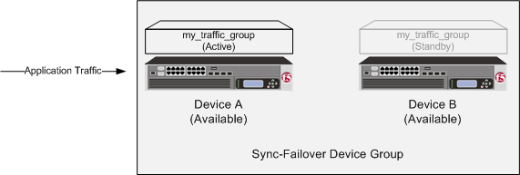 Traffic group states before failover
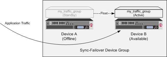 Traffic group states after failover
When Device A comes back online, the traffic group becomes standby on Device A.
Viewing the failover state of a device
- Display any screen of the BIG-IP Configuration utility.
- In the upper left corner of the screen, view the failover state of the device.
Viewing the state of a traffic group
- On the Main tab, click .
- In the Failover Status area of the screen, view the state of all traffic groups on the device.
Forcing a traffic group to a standby state
You perform this task when you want the selected traffic group on the local device to fail over to another device (that is, switch to a Standby state). Users typically perform this task when no automated method is configured for a traffic group, such as auto-failback or an HA group. By forcing the traffic group into a Standby state, the traffic group becomes active on another device in the device group. For device groups with more than two members, you can choose the specific device to which the traffic group fails over.
About active-standby vs. active-active configurations
A device group that contains only one traffic group is known as an active-standby configuration.
A device group that contains two or more traffic groups is known as an active-active configuration. For example, if you configure multiple virtual IP addresses on the BIG-IP system to process traffic for different applications, you might want to create separate traffic groups that each contains a virtual IP address and its relevant floating self IP address. You can then choose to make all of the traffic groups active on one device in the device group, or you can balance the traffic group load by making some of the traffic groups active on other devices in the device group.
Description of current and next-active devices
Within a Sync-Failover type of device group, a BIG-IP device sometimes has a specific designation with respect to a traffic group: either a current device or a next-active device.
| Designation | Description |
|---|---|
| Current Device | A current device is the device on which a traffic group is currently active. For example, if Device A is currently processing traffic using the objects in Traffic-Group-1, then Device A is the current device. If Device A becomes unavailable and Traffic-Group-1 fails over to Device C, then Device C becomes the current device. |
| Next-Active Device | A next-active device is the device on which a traffic group will become active if that traffic group eventually fails over to another device. For every active traffic group, the BIG-IP system assigns a corresponding next-active device. The next-active device for a traffic group is system-selected, based on criteria you specify when you configure the traffic group. |
About the next-active device
For every active traffic group on a device, the BIG-IP system identifies the device that is to be the next-active device if failover of that active traffic group occurs. A next-active device is the device on which a traffic group will become active if that traffic group eventually fails over to another device. This next-active designation changes continually depending on which devices are currently available in the device group.
There are various configuration options for you to choose from to affect the BIG-IP system's selection of the next-active device for failover:
- Load-aware failover
- An ordered list with auto-failback
- HA groups
What is load-aware failover?
Load-aware failover is a BIG-IP feature designed for use in a Sync-Failover device group. Configuring load-aware failover ensures that the traffic load on all devices in a device group is as equivalent as possible, factoring in any differences in device capacity and the amount of application traffic that traffic groups process on a device. The load-aware configuration option is most useful for device groups with heterogeneous hardware platforms or varying application traffic loads (or both).
For example, suppose you have a heterogeneous three-member device group in which one device (Bigip_C) has twice the hardware capacity of the other two devices (Bigip_A and Bigip_B).
If the device group has four active traffic groups that each process the same amount of application traffic, then the load on all devices is equivalent when devices Bigip_A and Bigip_B each contain one active traffic group, while device Bigip_C contains two active traffic groups.
The BIG-IP system implements load-aware failover by calculating a numeric, current utilization score for each device, based on numeric values that you specify for each device and traffic group relative to the other devices and traffic groups in the device group. The system then uses this current utilization score to determine which device is the best device in the group to become the next-active device when failover occurs for a traffic group.
The overall result is that the traffic load on each device is as equivalent as possible in a relative way, that is, factoring in individual device capacity and application traffic load per traffic group.
About device utilization calculation
The BIG-IP system on each device performs a calculation to determine the device's current level of utilization. This utilization level indicates the ability for the device to be the next-active device in the event that an active traffic group on another device must fail over within a heterogeneous device group.
The calculation that the BIG-IP performs to determine the current utilization of a device is based on these factors:
- Device capacity
- A local device capacity relative to other device group members.
- Active local traffic groups
- The number of active traffic groups on the local device.
- Active remote traffic groups
- The number of remote active traffic groups for which the local device is the next-active device.
- A multiplying load factor for each active traffic group
- A multiplier value for each traffic group. The system uses this value to weight each active traffic group's traffic load compared to the traffic load of each of the other active traffic groups in the device group.
The BIG-IP system uses all of these factors to perform a calculation to determine, at any particular moment, a score for each device that represents the current utilization of that device. This utilization score indicates whether the BIG-IP system should, in its attempt to equalize traffic load on all devices, designate the device as a next-active device for an active traffic group on another device in the device group.
The calculation that the BIG-IP performs for each device is:
(The sum of all local active traffic group HA load factors + The sum of all remote active traffic group HA load factors) / device capacityAbout HA capacity
For each device in a BIG-IP device group, you can assign a high availability (HA) capacity value. An HA capacity value is a number that represents the relative processing capacity of that device compared to the other devices in a device group. Assigning different HA capacity values to the devices in the device group is useful when the device group contains heterogeneous hardware platforms.
For example, if the device group has two devices with equal capacity and a third device that has twice the capacity of each of the other two devices, then you can assign values of 2, 2, and 4, respectively. You can assign any number to represent the HA capacity, as long as the number reflects the device's relative capacity compared to the other devices in the device group.
Specifying the HA capacity of a device
You perform this task when you have more than one type of hardware platform in a device group and you want to configure load-aware failover. Load-aware failover ensures that the BIG-IP system can intelligently select the next-active device for each active traffic group in the device group when failover occurs. As part of configuring load-aware failover, you define an HA capacity to establish the amount of computing resource that the device provides relative to other devices in the device group.
About the HA load factor
For each traffic group on a BIG-IP device, you can assign an high availability (HA) load factor. An HA load factor is a number that represents the relative application traffic load that an active traffic group processes compared to other active traffic groups in the device group.
For example, if the device group has two active traffic groups, and one traffic group processes twice the amount of application traffic as the other, then you can assign values of 4 and 2, respectively. You can assign any number for the HA load factor, as long as the number reflects the traffic group's relative load compared to the other active traffic groups.
About metrics for the HA load factor
User-specified values for the HA load factor can be based on different metrics. For example, suppose you have the three devices Bigip_A, Bigip_B, and Bigip_C, and each device has one active traffic group with an HA load factor of 2, 4, or 8 respectively. These values could indicate either of the following:
- If each traffic group contains one virtual address, then the sample factor values could indicate that the virtual server for Bigip_B processes twice the amount of traffic as that of Bigip_A, and the virtual server for Bigip_C processes twice the amount of traffic as that of Bigip_B.
- If the traffic group on Bigip_A contains one virtual address, the traffic group on Bigip_B contains two virtual addresses, and the traffic group on Bigip_C contains four virtual addresses, this could indicate that the virtual servers corresponding to those virtual addresses each process the same amount of traffic compared to the others.
Specifying an HA load factor for a traffic group
Viewing an HA traffic factor summary
This tmsh output shows a sample device group with two members and a total of two traffic groups. The user has configured a traffic load value (HA traffic factor) of 1 for tg-1 and 4 for tg-2. Both devices are the same hardware platform and so have a relative HA capacity value set to 0 (not shown).
For each device, the BIG-IP system determines the overall utilization score by adding together the loads for the active traffic groups. Thus:
- For bigip_A, the system adds together traffic loads of 1 (for its active traffic group) and 4 (if tg-2 fails over to bigip_A).
- For bigip_B, the system adds together traffic loads of 4 (for its active traffic group) and 1 (if tg-1 fails over to bigip_B).
Examples of device utilization scores
The utilization scores that the BIG-IP system calculates for the devices in a device group vary depending on:
- The differences in hardware capacity of the device group members
- The application load on each traffic group
- The number of active traffic groups on each device
Homogeneous device group with equivalent traffic group loads
In this example, all devices are the same hardware platform, and all three active traffic groups process equivalent application traffic load. Because the load is equivalent for all three traffic groups, the configured HA load factor for each traffic group is the same (in this case, 1).
The device utilization that the BIG-IP system calculates in this example is the sum of the two traffic load values (one per active traffic group).
| HA Capacity | Active traffic group | Traffic load | Potential active traffic group | Traffic load | Device utilization score |
|---|---|---|---|---|---|
| 0 | Traffic-group-1 | 1 | Traffic-group-2 | 1 | 1 + 1 = 2 |
| HA Capacity | Active traffic group | Traffic load | Potential active traffic group | Traffic load | Device utilization score |
|---|---|---|---|---|---|
| 0 | Traffic-group-2 | 1 | Traffic-group-3 | 1 | 1 + 1 = 2 |
| HA Capacity | Active traffic group | Traffic load | Potential active traffic group | Traffic load | Device utilization score |
|---|---|---|---|---|---|
| 0 | Traffic-group-3 | 1 | Traffic-group-1 | 1 | 1 + 1 = 2 |
Homogeneous device group with disparate traffic group loads
In this example, all devices are the same hardware platform. Also, each user-specified traffic group load factor is defined simply as 1, 4, or 8, to indicate that traffic-group-2 processes four times the application load of traffic-group-1, and that traffic-group-3 processes twice the application load of traffic-group-2.
The device utilization that the BIG-IP system calculates in this example is the sum of the two traffic load values (one per active traffic group).
| HA capacity | Active traffic group | Traffic load | Potential traffic group | Traffic load | Device utilization score |
|---|---|---|---|---|---|
| 0 | Traffic-group-1 | 1 | Traffic-group-2 | 4 | 1 + 4 = 5 |
| HA capacity | Active traffic group | Traffic load | Potential active traffic group | Traffic load | Device utilization score |
|---|---|---|---|---|---|
| 0 | Traffic-group-2 | 4 | Traffic-group-3 | 8 | 4 + 8 = 12 |
| HA capacity | Active traffic group | Traffic load | Potential active traffic group | Traffic load | Device utilization score |
|---|---|---|---|---|---|
| 0 | Traffic-group-3 | 8 | Traffic-group-1 | 1 | 8 + 1 = 9 |
This example shows that device Bigip_A is currently the least-used device, with a score of 5, while Bigip_B is the most used, with a score of 12. Therefore, the BIG-IP system would currently choose Bigip_A to receive failover traffic, to ensure that the application traffic load remains as equivalent as possible on all devices.
Heterogeneous device group with disparate traffic group loads
In this example, the load-aware configuration consists of a user-specified relative capacity for each device and a relative load for each active traffic group. The device group contains three heterogeneous devices, each with one active traffic group. Being different hardware platforms, the three devices each have a different user-specified relative device capacity, and each traffic group on a device has a different application traffic load.
The device utilization score that the BIG-IP system calculates in this example is the sum of two traffic load values on a device divided by the device capacity.
| HA capacity | Active traffic group | Traffic load | Potential active traffic group | Traffic load | Device utilization score |
|---|---|---|---|---|---|
| 10 | Traffic-group-1 | 1 | Traffic-group-2 | 4 | 5/10 = .50 |
| HA capacity | Active traffic group | Traffic load | Potential active traffic group | Traffic load | Device utilization score |
|---|---|---|---|---|---|
| 80 | Traffic-group-2 | 4 | Traffic-group-3 | 8 | 12/80 = .15 |
| HA capacity | Active traffic group | Traffic load | Potential active traffic group | Traffic load | Device utilization score |
|---|---|---|---|---|---|
| 20 | Traffic-group-3 | 8 | Traffic-group-1 | 1 | 9/20 = .45 |
This example shows the results of the calculations that the BIG-IP system performs for each device in the device group. For each device, the BIG-IP system factors in the device capacity, the load of the device's active traffic group, and the load of the next-active traffic group, to determine the current utilization of that device. The example shows that device Bigip_B, with a utilization score of .15, has the most available resource, despite having the heaviest traffic load. This is due to the large device capacity of 80 that the user specified relative to the other devices. Bigip_B is therefore most able to accept failover traffic from another device.
Heterogeneous device group with multiple active traffic groups on a single device
In this example, the load-aware configuration consists of a user-specified relative high availability (HA) capacity for each device and relative load for each active traffic group. The device group contains three heterogeneous devices, where Bigip_A and Bigip_B currently have one active traffic group each, while Bigip_C has two active traffic groups. Being different hardware platforms, the three devices each have a different user-specified relative device capacity, and each traffic group has a different relative application traffic load.
The device utilization score that the BIG-IP system calculates in this example is the sum of all traffic load values on a device divided by the device capacity.
| HA capacity | Active traffic group | Traffic load | Potential active traffic group | Traffic load | Device utilization score |
|---|---|---|---|---|---|
| 10 | Traffic-group-1 | 1 | Traffic-group-2 | 4 | 5/10 = .5 |
| HA capacity | Active traffic group | Traffic load | Potential active traffic group | Traffic load | Device utilization score |
|---|---|---|---|---|---|
| 80 | Traffic-group-2 | 4 | Traffic-group-3 | 8 | 12/80 = .15 |
| HA capacity | Active traffic group | Traffic load | Potential active traffic group | Traffic load | Device utilization score |
|---|---|---|---|---|---|
| 20 | Traffic-group-3 and Traffic-group-4 | 8 and 6 | Traffic-group-1 | 1 | 15/20 = .75 |
This example shows the results of the calculations that the BIG-IP system performs for each device in the device group. The example shows that device Bigip_B has the most available resource due to its low utilization score of .15. Conversely, Bigip_C has the highest utilization score (.75), due to having an additional active traffic group (Traffic-group-4) on the device with a relatively high traffic load value (6). In this case, Bigip_C is unlikely to become the next-active device on failover.
About matching device utilization values
In rare cases, the BIG-IP system might calculate that two or more devices in a device group have the same lowest device utilization score. In this case, the BIG-IP system needs an additional method for choosing the next-active device for an active traffic group.
The way that the BIG-IP system chooses the next-active device when device utilization scores match is by determining the management IP address of each matching device and then calculating a score based on the highest management IP address of those devices.
For example, if Bigip_A has an IP address of 192.168.20.11 and Bigip_B has an IP address of 192.168.20.12, and their utilization scores match, the BIG-IP system calculates a score based on the address 192.168.20.12.
What is an HA ordered list?
If you do not want to use the load-aware feature to determine the next-active device for a traffic group, you can configure a traffic group to use a static, ordered list of devices instead. This list of devices specifies the order in which you want those devices to become active for the traffic group if the traffic group must fail over.
If failover occurs and the first device in the list is unavailable, the BIG-IP system tries to make the traffic group active on the second device in the list. If the second device is also unavailable, the BIG-IP system tries to make the traffic group active on the third device, and so on.
If you do not specify an ordered list or if none of the devices in the list is available, the BIG-IP system attempts to use load-aware failover to choose the next-active device.
About auto-failback
The failover feature includes an option known as auto-failback. When you enable auto-failback, a traffic group that has failed over to another device fails back to a preferred device when that device is available. If you do not enable auto-failback for a traffic group, and the traffic group fails over to another device, the traffic group remains active on the new device until that device becomes unavailable.
You can enable auto-failback on a traffic group only when you have configured an ordered list with at least one entry, for that traffic group. In this case, if auto-failback is enabled and the traffic group has failed over to another device, then the traffic group fails back to the first device in the traffic group's ordered list (the preferred device) when that device becomes available.
If a traffic group fails over to another device, and the new device fails before the auto-failback timeout period has expired, the traffic group will still fail back, to the original device if available. The maximum allowed timeout value for auto-failback is 300 seconds.
Creating an HA ordered list
What is an HA group?
An HA group is a BIG-IP configuration object that specifies a set of trunks, pools, and/or VIPRION clusters for a device. When you associate an HA group with an instance of a traffic group on a specific device, the BIG-IP system calculates an overall health score on that device for the associated traffic group, based on trunk, pool, or cluster availability. This HA health score determines the device that the associated traffic group should be active on at any given time and then triggers failover to that device if necessary. Trunk configurations are not synchronized between devices, which means that the number of trunk members on each device in the device group can vary whenever a trunk loses or gains members, thereby affecting the health score.
The ability of an HA group to choose a next-active device and trigger failover for a traffic group distinguishes the HA groups feature from the other failover methods (load-aware failover and HA order). Although the load-aware and HA order failover methods also identify the next-active device for a traffic group, these methods do not trigger failover; instead, failover is triggered by standard system, gateway, or VLAN fail-safe configuration.
The most common reason for configuring HA groups is to ensure that a traffic group fails over to another device when trunk availability for a specific device falls below a certain level. Also, failover triggered by an HA group is noticeably faster than failover triggered by system, gateway, or VLAN failure.
As an example, suppose that Bigip_A and Bigip_B each has the traffic group traffic-group-1. If you want traffic-group-1 to always be active on the device with the highest HA score, you can create a unique HA group for that traffic group, on each device, that defines a minimum value for acceptable link availability. You can then associate the local HA group with traffic-group-1 on each device. More specifically, on Bigip_A, you can create an HA group named HA_GroupA and associate it with traffic-group-1. On Bigip_B, you can create a different HA group, HA_GroupB, and also associate it with traffic-group-1. This ensures that traffic-group-1 is always active on the device with the best link availability at any given time.
Factors in HA health score calculation
The BIG-IP system calculates an HA health score per traffic group on a device, based on the values that you specify when you configure the feature.
A weight value (required)
A weight is a health value that you assign to each member of the HA group (that is, a pool, trunk, and/or VIPRION cluster). The weight that you assign to each HA group member must be in the range of 10 through 100.
The maximum overall score that the BIG-IP system can potentially calculate is the sum of the individual weights for the HA group members, plus the active bonus value. There is no limit to the sum of the member weights for the HA group as a whole.
A threshold value (optional)
For each member of an HA group, you can specify a setting known as a threshold. A threshold is a value that specifies the number of object members that must be available to prevent failover. If the number of available object members is less than the threshold, the BIG-IP system assigns a score of 0 to the HA group member so that the score of that HA group member no longer contributes to the overall score.
For example, if a trunk in the HA group has four trunk members and you specify a threshold value of 3, and the number of available trunk members falls to 2, then the trunk contributes a score of 0 to the total score for the traffic group or device.
If the number of available object members equals or exceeds the threshold value, or you do not specify a threshold, the BIG-IP system calculates the score as described previously, by multiplying the percentage of available object members by the weight for each HA group member and then adding the scores to determine the overall score for the traffic group or device.
The threshold that you define for pools can be less than or equal to the number of members in the pool. For clusters, the threshold can be less than or equal to the number of possible blades in the chassis, and for trunks, the threshold can be less than or equal to the number of possible members in a trunk for that platform.
An active bonus value (optional)
An active bonus is an amount that the BIG-IP system automatically adds to the overall HA score of an active traffic group or device. An active bonus ensures that the traffic group or device remains active when its score would otherwise temporarily fall below the score of the standby traffic group on another device. The active bonus that you configure can be in the range of 0 to 100.
A common reason to specify an active bonus is to prevent failover due to flapping, the condition where failover occurs frequently as a trunk member switches rapidly between availability and unavailability. In this case, you might want to prevent the HA scoring feature from triggering failover each time a trunk member is lost. You might also want to prevent the HA scoring feature from triggering failover when you make minor changes to the BIG-IP system configuration, such as adding or removing a trunk member.
For example, suppose that the HA group for a traffic group on each device contains a trunk with four members, and you assign a weight of 30 to each trunk. Without an active bonus defined, if the trunk on one device loses some number of members, failover occurs because the overall calculated score for that traffic group becomes lower than that of a peer device. You can prevent this failover from occurring by specifying an active bonus value.
The BIG-IP system uses an active bonus to contribute to the HA score of an active traffic group only; the BIG-IP system never uses an active bonus to contribute to the score of a standby traffic group.
To decide on an active bonus value, calculate the trunk score for some number of failed members (such as one of four members), and then specify an active bonus that results in a trunk score that is greater than the weight that you assigned to the trunk.
For example, if you assigned a weight of 30 to the trunk, and one of the four trunk members fails, the trunk score becomes 23 (75% of 30), putting the traffic group at risk for failover. However, if you specified an active bonus of 8 or higher, failover would not actually occur, because a score of 8 or higher, when added to the score of 23, is greater than 30.
Example of HA health score calculation
This example illustrates the way that HA group configuration results in the calculation of an HA health score for a traffic group on a specific device. Suppose that you previously created an HA group for traffic-group-1 on all device group members and that traffic-group-1 is currently active on device Bigip_A. Also suppose that on device Bigip_B, the HA group for traffic-group-1 consists of two pools and a trunk, with weights that you assign:
| HA group object | Member count | User-specified weight |
|---|---|---|
| http_pool | 8 | 50 |
| ftp_pool | 6 | 20 |
| trunk1 | 4 | 30 |
Now suppose that on device Bigip_B, the current member availability of pool http_pool, pool ftp_pool, and trunk trunk1 is 5, 6, and 3, respectively. The resulting HA score that the BIG-IP system calculates for traffic-group-1 on Bigip_B is shown here:
| HA group object | Member count | Available member count | User-specified weight | Current HA score |
|---|---|---|---|---|
| http_pool | 8 | 5 (62.5%) | 50 | 31 (60% x 50) |
| ftp_pool | 6 | 6 (100%) | 20 | 20 (100% x 20) |
| trunk1 | 4 | 3 (75%) | 30 | 23 (75% x 30) |
| Total score: 74 |
In this example, the total HA score for traffic-group-1 on Bigip_B is currently 74. If this score is currently the highest score in the device group for traffic-group-1, then traffic-group-1 will automatically failover and become active on Bigip_B.
Creating an HA group
You use this task to create an HA group for a traffic group on a device in a BIG-IP device group. Also known as fast failover, an HA group is most useful when you want an active traffic group on a device to fail over to another device based on trunk and pool availability, and on VIPRION systems, also cluster availability. You can create multiple HA groups on a single device, and you associate each HA group with the local instance of a traffic group.
Associating an HA group with a traffic group
You use this task to associate an HA group with an existing traffic group. Also known as fast failover, this configuration option is most useful when you want an active traffic group to fail over to another device due to trunk, pool, and/or VIPRION cluster availability specifically. When you configure an HA group for a traffic group, you ensure that the traffic group, when active, fails over to the device on which the traffic group has the highest HA score.
About MAC masquerade addresses
A MAC masquerade address is a unique, floating Media Access Control (MAC) address that you create and control. You can assign one MAC masquerade address to each traffic group on a BIG-IP device. By assigning a MAC masquerade address to a traffic group, you indirectly associate that address with any floating IP addresses (services) associated with that traffic group. With a MAC masquerade address per traffic group, a single VLAN can potentially carry traffic and services for multiple traffic groups, with each service having its own MAC masquerade address.
A primary purpose of a MAC masquerade address is to minimize ARP communications or dropped packets as a result of a failover event. A MAC masquerade address ensures that any traffic destined for the relevant traffic group reaches an available device after failover has occurred, because the MAC masquerade address floats to the available device along with the traffic group. Without a MAC masquerade address, on failover the sending host must relearn the MAC address for the newly-active device, either by sending an ARP request for the IP address for the traffic or by relying on the gratuitous ARP from the newly-active device to refresh its stale ARP entry.
The assignment of a MAC masquerade address to a traffic group is optional. Also, there is no requirement for a MAC masquerade address to reside in the same MAC address space as that of the BIG-IP device.


