Manual Chapter : Configuring IPsec in Transport Mode between Two BIG-IP Systems

Applies To:

Show Versions Show Versions

BIG-IP AAM

  • 14.0.1, 14.0.0, 13.1.5, 13.1.4, 13.1.3, 13.1.1, 13.1.0

BIG-IP APM

  • 14.0.1, 14.0.0, 13.1.5, 13.1.4, 13.1.3, 13.1.1, 13.1.0

BIG-IP LTM

  • 14.0.1, 14.0.0, 13.1.5, 13.1.4, 13.1.3, 13.1.1, 13.1.0

BIG-IP AFM

  • 14.0.1, 14.0.0, 13.1.5, 13.1.4, 13.1.3, 13.1.1, 13.1.0

BIG-IP ASM

  • 14.0.1, 14.0.0, 13.1.5, 13.1.4, 13.1.3, 13.1.1, 13.1.0
Manual Chapter

Overview: Configuring IPsec in Transport mode between two BIG-IP systems

You can configure IPsec when you want to use a protocol other than SSL to secure traffic that traverses a wide area network (WAN), from one BIG-IP® system to another. By following this procedure, you can configure an IKE peer to negotiate Phase 1 Internet Security Association and Key Management Protocol (ISAKMP) security associations for the secure channel between two systems. You can also configure a custom traffic selector and a custom IPsec policy that use this secure channel to generate IPsec Transport mode (Phase 2) security associations (SAs).

IPsec tunnel deployment illustration

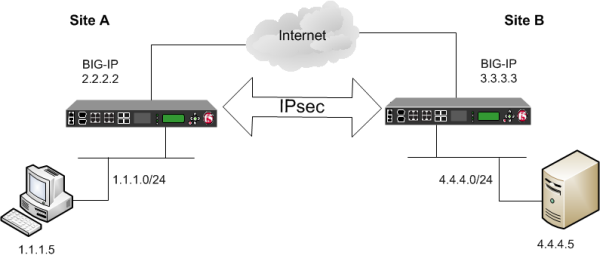
Example of an IPsec deployment

About negotiation of security associations

The way to dynamically negotiate security associations is to configure the Internet Key Exchange (IKE) protocol, which is included in the IPsec protocol suite. When you configure the IKE protocol, two IPsec tunnel endpoints (IKE peers) open a secure channel using an ISAKMP security association (ISAKMP-SA) to initially negotiate the exchange of peer-to-peer authentication data. This exchange is known as Phase 1 negotiation.

After Phase 1 is complete and the secure channel is established, Phase 2 negotiation begins, in which the IKE peers dynamically negotiate the authentication and encryption algorithms to use to secure the payload. Without IKE, the system cannot dynamically negotiate these security algorithms.

About IPsec Transport mode

Transport mode causes the IPsec protocol to encrypt only the payload of an IP packet. The protocol then encloses the encrypted payload in a normal IP packet. Traffic sent in Transport mode is less secure than traffic sent in Tunnel mode, because the IP header in each packet is not encrypted.

Note:The BIG-IP does not support Transport Mode with IKEv2.

About BIG-IP components of the IPsec protocol suite

The IPsec protocol suite on the BIG-IP® system consists of these configuration components:

IKE peers
An IKE peer is a configuration object of the IPsec protocol suite that represents a BIG-IP system on each side of the IPsec tunnel. IKE peers allow two systems to authenticate each other (known as IKE Phase 1). The BIG-IP system supports two versions of the IKE protocol: Version 1 (IKEv1) and Version 2 (IKEv2). The BIG-IP system includes the default IKE peer, named anonymous, which is configured to use Version 1.
Note: The BIG-IP system currently supports IKEv2 only in Tunnel mode, and does not support IPComp or NAT-T with IKEv2.
IPsec policies
An IPsec policy is a set of information that defines the specific IPsec protocol to use (ESP or AH), and the mode (Transport, Tunnel, or iSession). For Tunnel mode, the policy also specifies the endpoints for the tunnel, and for IKE Phase 2 negotiation, the policy specifies the security parameters to be used in that negotiation. The way that you configure the IPsec policy determines the way that the BIG-IP system manipulates the IP headers in the packets. The BIG-IP system includes two default IPsec policies, named default-ipsec-policy and default-ipsec-policy-isession. A common configuration includes a bidirectional policy on each BIG-IP system.
Traffic selectors
A traffic selector is a packet filter that defines what traffic should be handled by a IPsec policy. You define the traffic by source and destination IP addresses and port numbers. A common configuration includes a bidirectional traffic selector on each BIG-IP system.

About IP Payload Compression Protocol (IPComp)

IP Payload Compression Protocol (IPComp) is a protocol that reduces the size of IP payloads by compressing IP datagrams before fragmenting or encrypting the traffic. IPComp is typically used to improve encryption and decryption performance, thus increasing bandwidth utilization. Using an IPsec ESP tunnel can result in packet fragmentation, because the protocol adds a significant number of bytes to a packet. The additional bytes can push the packet over the maximum size allowed on the outbound link. Using compression is one way to mitigate fragmentation. IPComp is an option when you create a custom IPsec policy.

Task summary

With this task, you can configure the IPsec and IKE protocols to secure traffic that traverses a wide area network (WAN), such as from one data center to another.

Before you begin configuring IPsec and IKE, verify that these modules, system objects, and connectivity exist on the BIG-IP systems in both the local and remote locations:

BIG-IP Local Traffic Manager™
This module directs traffic securely and efficiently to the appropriate destination on a network.
Self IP address
Each BIG-IP system must have at least one self IP address, to be used in specifying the ends of the IPsec tunnel.
The default VLANs
These VLANs are named external and internal.
BIG-IP connectivity
Verify the connectivity between the client or server and its BIG-IP device, and between each BIG-IP device and its gateway. For example, you can use ping to test this connectivity.

Task list

Creating a forwarding virtual server for IPsec

For IPsec, you create a forwarding (IP) type of virtual server to intercept IP traffic and direct it over the tunnel. With a forwarding (IP) virtual server, destination address translation and port translation are disabled.
  1. On the Main tab, click Local Traffic > Virtual Servers .
    The Virtual Server List screen opens.
  2. Click the Create button.
    The New Virtual Server screen opens.
  3. In the Name field, type a unique name for the virtual server.
  4. From the Type list, select Forwarding (IP).
  5. In the Destination Address field, type a wildcard network address in CIDR format, such as 0.0.0.0/0 for IPv4 or ::/0 for IPv6, to accept any traffic.
  6. From the Service Port list, select *All Ports.
  7. From the Protocol list, select *All Protocols.
  8. From the VLAN and Tunnel Traffic list, retain the default selection, All VLANs and Tunnels.
  9. Click Finished.

Creating an IKE peer

The IKE peer object identifies to the system you are configuring the other BIG-IP system with which it communicates during Phase 1 negotiations. The IKE peer object also specifies the specific algorithms and credentials to be used for Phase 1 negotiation.

Important: You must perform these steps on both BIG-IP systems.
  1. On the Main tab, click Network > IPsec > IKE Peers .
  2. Click the Create button.
    The New IKE Peer screen opens.
  3. In the Name field, type a unique name for the IKE peer.
  4. In the Description field, type a brief description of the IKE peer.
  5. In the Remote Address field, type the IP address of the BIG-IP system that is remote to the system you are configuring.
    To specify a route domain ID in an IP address, use the format n.n.n.n%ID.
    Note: When you use IKEv1, the BIG-IP system supports a maximum of 512 route domains.
  6. For the State setting, retain the default value, Enabled.
  7. For the Version setting, select either version or both versions.
    To successfully create an IPsec tunnel, the remote IKE peer must use the same version.
    Note: Currently, IKEv2 is supported only for Tunnel mode, which you specify when you create the IPsec policy. Some parameters are supported only by IKEv1, as indicated on the IKE Peer screens.

    If you select both versions:

    • And the system you are configuring is the IPsec initiator, the system tries using IKEv2 for negotiation. If the remote peer does not support IKEv2, the IPsec tunnel fails. To use IKEv1 in this case, clear the Version 2 check box, and try again.
    • And the system you are configuring is the IPsec responder, the IPsec initiator system determines which IKE version to use.
  8. For the IKE Phase 1 Algorithms area, retain the default values, or select the options that are appropriate for your deployment.
  9. In the IKE Phase 1 Credentials area, for the Authentication Method setting, select the option appropriate for your deployment.
    • If you select RSA Signature (default), the Certificate, Key, and Verify Peer Certificate settings are available. If you have your own certificate file, key file, and certificate authority (CA), F5 recommends, for security purposes, that you specify these files in the appropriate fields. To reveal all these fields, select the Verify Peer Certificate check box. If you retain the default settings, leave the check box cleared.
      Important: If you select the check box, you must provide a certificate file, key, and certificate authority.
      Note: This option is available only for IKEv1.
    • If you select Preshared Key, type the key in the Preshared Key field that becomes available.
    Note: The key you type must be the same at both ends of the tunnel.
  10. If you selected Version 2, select a traffic selector from the Traffic Selector list in the Common Settings area.
    Only traffic selectors that are valid for IKEv2 appear on the list. The default traffic selector is not included, because it is not supported in IKEv2. Also, you can associate a traffic selector with only one IKE peer, so traffic selectors already associated with other peers are not displayed.
  11. If you selected Version 2, select Override from the Presented ID list, and enter a value in the Presented ID Value field.
    This value must match the Verified ID Value field on the remote IKE peer.
  12. If you selected Version 2, select Override from the Verified ID list, and enter a value in the Verified ID Value field.
    This value must match the Presented ID Value field on the remote IKE peer.
  13. Click Finished.
    The screen refreshes and displays the new IKE peer in the list.
  14. Repeat this task on the BIG-IP system in the remote location.
You now have an IKE peer defined for establishing a secure channel.

Creating a bidirectional IPsec policy

You create a custom IPsec policy when you want to use a policy other than the default IPsec policy (default-ipsec-policy or default-ipsec-policy-isession). A typical reason for creating a custom IPsec policy is to configure IPsec to operate in Tunnel rather than Transport mode. Another reason is to add payload compression before encryption. If you are using IKEv2, you must create a custom IPsec policy to specify in the traffic selector you create.

Important: You must perform this task on both BIG-IP systems.
  1. On the Main tab, click Network > IPsec > IPsec Policies .
  2. Click the Create button.
    The New Policy screen opens.
  3. In the Name field, type a unique name for the policy.
  4. In the Description field, type a brief description of the policy.
  5. For the IPsec Protocol setting, retain the default selection, ESP.
  6. From the Mode list, select Transport.
  7. For the Authentication Algorithm setting, retain the default value, or select the algorithm appropriate for your deployment.
  8. For the Encryption Algorithm setting, retain the default value, or select the algorithm appropriate for your deployment.
  9. For the Perfect Forward Secrecy setting, select the option appropriate for your deployment.
  10. For the IPComp setting, specify whether to use IPComp encapsulation, which performs packet-level compression before encryption:
    • Retain the default value None, if you do not want to enable packet-level compression before encryption.
    • Select DEFLATE to enable packet-level compression before encryption.
  11. For the Lifetime setting, retain the default value, 1440.
    This is the length of time (in minutes) before the current security association expires.
  12. Click Finished.
    The screen refreshes and displays the new IPsec policy in the list.
  13. Repeat this task on the BIG-IP system in the remote location.

Creating a bidirectional IPsec traffic selector

The traffic selector you create filters traffic based on the IP addresses and port numbers that you specify, as well as the custom IPsec policy you assign.
Important: You must perform this task on both BIG-IP systems.
  1. On the Main tab, click Network > IPsec > Traffic Selectors .
  2. Click Create.
    The New Traffic Selector screen opens.
  3. In the Name field, type a unique name for the traffic selector.
  4. In the Description field, type a brief description of the traffic selector.
  5. For the Order setting, retain the default value (Last).
    If traffic can be matched to multiple selectors, this setting specifies the priority. Traffic is matched to the traffic selector with the highest priority (lowest number).
  6. From the Configuration list, select Advanced.
  7. For the Source IP Address setting, type an IP address.
    This IP address should be the host or network address from which the application traffic originates. To specify a route domain ID in an IP address, use the format n.n.n.n%ID.
    Note: When you use IKEv1, the BIG-IP system supports a maximum of 512 route domains.
    This table shows sample source IP addresses for BIG-IP A and BIG-IP B.
    System Name Source IP Address
    BIG-IP A 1.1.1.0/24
    BIG-IP B 4.4.4.0/24
  8. From the Source Port list, select the source port for which you want to filter traffic, or retain the default value *All Ports.
  9. For the Destination IP Address setting, type an IP address.
    This IP address should be the final host or network address to which the application traffic is destined. To specify a route domain ID in an IP address, use the format n.n.n.n%ID.
    Note: When you use IKEv1, the BIG-IP system supports a maximum of 512 route domains.
    This table shows sample destination IP addresses for BIG-IP A and BIG-IP B.
    System Name Destination IP Address
    BIG-IP A 4.4.4.0/24
    BIG-IP B 1.1.1.0/24
  10. From the Destination Port list, select the destination port for which you want to filter traffic, or retain the default value * All Ports.
  11. From the Protocol list, select the protocol for which you want to filter traffic.
    You can select * All Protocols, TCP, UDP, ICMP, or Other. If you select Other, you must type a protocol name.
  12. From the Direction list, select Both.
  13. From the IPsec Policy Name list, select the name of the custom IPsec policy that you created.
  14. Click Finished.
    The screen refreshes and displays the new IPsec traffic selector in the list.
  15. Repeat this task on the BIG-IP system in the remote location.

Verifying IPsec connectivity for Transport mode

After you have configured an IPsec tunnel and before you configure additional functionality, you can verify that the tunnel is passing traffic.

Note: Only data traffic triggers the establishment of the tunnel.
.
  1. Access the tmsh command-line utility.
  2. Before sending traffic, type this command at the prompt.
    tmsh modify net ipsec ike-daemon ikedaemon log-level info
    This command increases the logging level to display the INFO messages that you want to view.
  3. Send data traffic to the Destination IP Address in the traffic selector.
  4. Check the IKE Phase 1 negotiation status by typing this command at the prompt.
    racoonctl -l show-sa isakmp
    This example shows a result of the command. Destination is the tunnel remote IP address.
    Destination Cookies ST S V E Created Phase2 165.160.15.20.500 98993e6 . . . 22c87f1 9 I 10 M 2012-06-27 16:51:19 1
    

    This table shows the legend for interpreting the result.

    Column Displayed Description
    ST (Tunnel Status) 1 Start Phase 1 negotiation
      2 msg 1 received
      3 msg 1 sent
      4 msg 2 received
      5 msg 2 sent
      6 msg 3 received
      7 msg 3 sent
      8 msg 4 received
      9 isakmp tunnel established
      10 isakmp tunnel expired
    S I Initiator
      R Responder
    V (Version Number) 10 ISAKMP version 1.0
    E (Exchange Mode) M Main (Identity Protection)
      A Aggressive
    Phase2 <n> Number of Phase 2 tunnels negotiated with this IKE peer
  5. Check the IKE Phase 2 negotiation status by typing this command at the prompt.
    racoonctl -ll show-sa internal
    This example shows a result of this command. Source is the tunnel local IP address. Destination is the tunnel remote IP address.
     Source Destination Status Side 10.100.20.3 165.160.15.20 sa established [R]
    

    This table shows the legend for interpreting the result.

    Column Displayed
    Side I (Initiator)
      R (Responder)
    Status init
      start
      acquire
      getspi sent
      getspi done
      1st msg sent
      1st msg recvd
      commit bit
      sa added
      sa established
      sa expired
  6. To verify the establishment of dynamic negotiated Security Associations (SAs), type this command at the prompt.
    tmsh show net ipsec ipsec-sa
    For each tunnel, the output displays IP addresses for two IPsec SAs, one for each direction, as shown in the example.
    IPsec::SecurityAssociations
    10.100.20.3  ->  165.160.15.20  SPI(0x164208ae)  out  esp  (tmm: 0)
    165.160.15.20  ->  10.100.20.3  SPI(0xfa2ca7a8)  in   esp  (tmm: 0)
                        
    
  7. To display the details of the dynamic negotiated Security Associations (SAs), type this command at the prompt.
    tmsh show net ipsec ipsec-sa all-properties
    For each tunnel, the output displays the details for the IPsec SAs, as shown in the example.
    IPsec::SecurityAssociations
    10.100.20.3 -> 165.160.15.20                                         
    -----------------------------------------------------------------------------------------------------
      tmm: 0                                                                
      Direction: out;  SPI: 0x164208ae(373426350);  Policy ID: 0x87e9(34793)
      Protocol: esp;  Mode: transport;  State: mature                       
      Authenticated Encryption : aes-gcm128                                 
      Current Usage: 196 bytes                                              
      Hard lifetime: 51 seconds; unlimited bytes                            
      Soft lifetime: 39 seconds; unlimited bytes                            
      Replay window size: 64                                                
      Last use: 01/24/2014:14:03                                                Create:  01/24/2014:14:03
    
    165.160.15.20 -> 10.100.20.3                                         
    -----------------------------------------------------------------------------------------------------
      tmm: 0                                                                
      Direction: in;  SPI: 0xfa2ca7a8(4197230504);  Policy ID: 0x87e8(34792)
      Protocol: esp;  Mode: transport;  State: mature                       
      Authenticated Encryption : aes-gcm128                                 
      Current Usage: 264 bytes                                              
      Hard lifetime: 51 seconds; unlimited bytes                            
      Soft lifetime: 39 seconds; unlimited bytes                            
      Replay window size: 64                                                
      Last use: 01/24/2014:14:03                                                Create:  01/24/2014:14:03
                        
    
  8. To filter the Security Associations (SAs) by traffic selector, type this command at the prompt.
    tmsh show net ipsec ipsec-sa traffic-selector ts_codec

    You can also filter by other parameters, such as SPI (spi), source address (src_addr), or destination address (dst_addr)

    The output displays the IPsec SAs that are associated with the traffic selector specified, as shown in the example.
    IPsec::SecurityAssociations
    10.100.20.3  ->  165.160.15.20  SPI(0x164208ae)  out  esp  (tmm: 0)
    165.160.15.20  ->  10.100.20.3  SPI(0xfa2ca7a8)  in   esp  (tmm: 0)
                        
    
  9. Check the IPsec stats by typing this command at the prompt.
    tmsh show net ipsec-stat
    If traffic is passing through the IPsec tunnel, the stats will increment.
     
    -------------------------------------------------------------------
    Net::Ipsec
    Cmd Id           Mode  Packets In  Bytes In  Packets Out  Bytes Out
    -------------------------------------------------------------------
    0           TRANSPORT      353.9K    252.4M        24.9K       1.8M
    0           TRANSPORT      117.9K     41.0M       163.3K      12.4M
    0              TUNNEL           0         0            0          0
    0              TUNNEL           0         0            0          0
    1              TUNNEL           0         0            0          0
    2              TUNNEL           0         0            0          0                       
                        
    
  10. If the SAs are established, but traffic is not passing, type this command at the prompt.
    tmsh delete net ipsec ipsec-sa
    This action deletes the IPsec tunnels. Sending new traffic triggers SA negotiation and establishment.
  11. If traffic is still not passing, type this command at the prompt.
    racoonctl flush-sa isakmp
    This action brings down the control channel. Sending new traffic triggers SA negotiation and establishment.
  12. View the /var/log/racoon.log to verify that the IPsec tunnel is up.
    These lines are examples of the messages you are looking for.
    2012-06-29 16:45:13: INFO: ISAKMP-SA established 10.100.20.3[500]-165.160.15.20[500] spi:3840191bd045fa51:673828cf6adc5c61
    2012-06-29 16:45:14: INFO: initiate new phase 2 negotiation: 10.100.20.3[500]<=>165.160.15.20[500]
    2012-06-29 16:45:14: INFO: IPsec-SA established: ESP/Transport 165.160.15.20[0]->10.100.20.3[0] spi=2403416622(0x8f413a2e)
    2012-06-29 16:45:14: INFO: IPsec-SA established: ESP/Transport 10.100.20.3[0]->165.160.15.20[0] spi=4573766(0x45ca46                    
                        
    
  13. For troubleshooting, increase the debug level by typing this command at the prompt.
    tmsh modify net ipsec ike-daemon ikedaemon log-level debug2
    Important: Use this command only for debugging. It creates a large log file, and can slow the tunnel negotiation.
    Note: Using this command flushes existing SAs.
  14. After you view the results, return the debug level to normal to avoid excessive logging by typing this command at the prompt.
    tmsh modify net ipsec ike-daemon ikedaemon log-level info
    Note: Using this command flushes existing SAs.

Implementation result

You now have a secure IPsec channel for securing traffic that traverses the WAN, from one BIG-IP system to another.