Manual Chapter : Using NAT64 to Map IPv6 Addresses to IPv4 Destinations

Applies To:

Show Versions Show Versions

BIG-IP LTM

  • 11.5.10, 11.5.9, 11.5.8, 11.5.7, 11.5.6, 11.5.5, 11.5.4, 11.5.3, 11.5.2, 11.5.1
Manual Chapter

Using NAT64 to Map IPv6 Addresses to IPv4 Destinations

About NAT64

For the BIG-IP® system CGNAT module, NAT64 is the NAT type that maps IPv6 subscriber private addresses to IPv4 Internet public addresses. NAT64 translates subscriber IPv6 addresses to public Internet IPv4 addresses and allows Internet traffic from an IPv6 client to reach a public IPv4 server. The CGNAT module processes NAT64 traffic, as defined in RFC 6146 for TCP and UDP addresses.

NAT64 network diagram

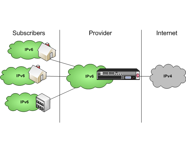
Diagram of a NAT64 network

Task summary

Creating a NAT64 LSN pool

The CGNAT module must be enabled through System > Resource Provisioning before you can configure LSN pools.
A NAT64 LSN pool contains the set of IPv4 address ranges that will be used on the public Internet.
  1. On the Main tab, click Carrier Grade NAT > LSN Pools .
    The LSN Pool List screen opens.
  2. Click Create.
  3. In the Name field, type a unique name.
  4. For the Member List setting, in the Address/Prefix Length field, type an address and a prefix length and click Add.
  5. Click Finished.
Your LSN pool is now ready, and you can continue to configure your CGNAT.

Creating a virtual server for an LSN pool

Virtual servers are matched based on source (client) addresses. Define a virtual server that references the CGNAT profile and the LSN pool.
  1. On the Main tab, click Carrier Grade NAT > Virtual Servers .
    The Virtual Servers screen opens.
  2. Click the Create button.
    The New Virtual Server screen opens.
  3. In the Name field, type a unique name for the virtual server.
  4. From the Type list, select Performance (Layer 4).
  5. For the Destination setting, in the Address field, type 0.0.0.0 to allow all traffic to be translated.
  6. In the Service Port field, type * or select * All Ports from the list.
  7. From the VLAN and Tunnel Traffic list, select Enabled on. Then, for the VLANs and Tunnels setting, move the VLAN or VLANs on which you want to allow the virtual servers to share traffic from the Available list to the Selected list.
  8. For the LSN Pool setting, select the pool that this server will draw on for translation addresses.
  9. In the Resources area of the screen, for the iRules setting, select the name of the iRule that you want to assign and using the Move button, move the name from the Available list to the Enabled list.
  10. Click Finished.
The custom CGNAT virtual server now appears in the CGNAT Virtual Servers list.

Configuring a SIP ALG profile

You must have a SIP registrar and proxy configured prior to using a SIP ALG profile.
The SIP ALG profile provides the CGNAT module with enough protocol and service knowledge to make specified packet modifications to the IP and TCP/UDP headers, as well as the SIP payload during translation.
Important: Edit only copies of the included ALG profiles to avoid unwanted propagation of settings to other profiles that use the included profiles as parents.
  1. On the Main tab, click Carrier Grade NAT > ALG Profiles > SIP .
    The SIP screen opens and displays a list of available SIP ALG profiles.
  2. Click Create.
    The New SIP Profile screen opens.
  3. Type a name for the new profile.
  4. From the Parent Profile list, ensure that sip is selected as the new profile.
  5. Select the Custom check box on the right.
  6. For the Terminate on BYE setting, select the Enabled check box.
  7. Select the Dialog Aware check box.
  8. Type a unique community string in the Community field.
  9. From the Insert Via Header list, select Enabled.
  10. Click Finished to save the new SIP ALG profile.
  11. You must also create two virtual servers: one to handle SIP TCP traffic and another to handle SIP UDP traffic.
    1. Create a host virtual server with a Source address of 0.0.0.0/0 and a Destination type set as Network, as well as a Mask of 0.0.0.0 and a Service Port of 5060.
    2. From the Protocol list, select TCP.
    3. From the SIP Profile list, select a SIP profile.
    4. From the VLAN and Tunnel Traffic list, select All VLANs and Tunnels.
    5. From the LSN Pool list, select an LSN pool.
    6. Repeat the virtual server creation procedure, and then from the Protocol list, choose UDP. Also choose the SSL client, SSL server, and Authentication profiles from their respective lists as needed.
    You now have a TCP and UDP virtual server to handle SIP traffic.
You now have a SIP ALG profile for use by CGNAT.

Configuring a CGNAT iRule

You create iRules® to automate traffic forwarding for XML content-based routing. When a match occurs, an iRule event is triggered, and the iRule directs the individual request to an LSN pool, a node, or virtual server.
  1. On the Main tab, click Carrier Grade NAT > iRules .
    The iRule List screen opens.
  2. Click Create.
  3. In the Name field, type a 1 to 31 character name, such as cgn_https_redirect_iRule.
  4. In the Definition field, type the syntax for the iRule using Tool Command Language (Tcl) syntax.
    For complete and detailed information about iRules syntax, see the F5 Networks DevCentral web site (http://devcentral.f5.com).
  5. Click Finished.
You now have an iRule to use with a CGNAT virtual server.