Applies To:
Show Versions
BIG-IP LTM
- 11.5.10, 11.5.9, 11.5.8, 11.5.7, 11.5.6, 11.5.5, 11.5.4, 11.5.3, 11.5.2, 11.5.1
Using PBA Mode to Reduce CGNAT Logging
Overview: Using PBA mode to reduce CGNAT logging
Port block allocation (PBA) mode is a translation mode option that reduces CGNAT logging, by logging only the allocation and release of each block of ports. When a subscriber first establishes a network connection, the BIG-IP® system reserves a block of ports on a single IP address for that subscriber. The system releases the block when no more connections are using it. This reduces the logging overhead because the CGNAT logs only the allocation and release of each block of ports.
About PBA address translation mode
Port Block Allocation (PBA) mode provides you with the ability to log only the allocation and release of port blocks for a subscriber, instead of separately logging each network address translation (NAT) session as a separate translation event, as with network address and port translation (NAPT), thus reducing the number of log entries while maintaining legal mapping and reverse mapping requirements.
Restrictions
Configuration restrictions for PBA mode include these constraints.
- PBA mode is compatible only with SP-DAG. If a VLAN is used that is not compatible with SP-DAG, then NAPT mode becomes active and an error is logged.
- You can configure overlapping LSN prefixes only between pools of the same type, to ensure correct reverse mapping from a translation address and port to a subscriber.
- The system allocates one primary port block for each subscriber, with the allocation of an additional overflow port block, as necessary.
- The Client Connection Limit value constrains the number of subscriber connections, preventing any one subscriber from using an excessive number of connections.
- PBA mode is available with NAT44, NAT64, and DS-Lite.
Behavior Characteristics
PBA mode manages connections by means of the following characteristics.
- A zombie port block, which is a port block that has reached the Block Lifetime limit but cannot be released due to active connections, is released when all active connections become inactive, or when the Zombie Timeout value is reached.
- Port allocation within an active port block occurs until all available ports become allocated, or until the Block Lifetime limit is exceeded.
- The Block Idle Timeout value specifies the period between when the last connection using a port block is freed and when the port block can be reused.
Reduced Logging
When you use PBA mode, a log entry is sent when a block of ports is allocated for a subscriber, and again when a block of ports is released. Log entries include the range of ports (that is, the port block) from the start port through the end port. Several logging destinations are available for PBA mode, including Syslog, Splunk, and IPFIX.
About configuring PBA mode with route domains
Port block allocation (PBA) mode can be used with route domains to configure multiple subscriber networks in separate route domains. You can also partition subscriber networks and the Internet by using route domains.
A route domain that is used for the translation entry is not the subscriber route domain. The subscriber route domain is, instead, applied to the egress interface.
In the following configuration, multiple subscribers can connect to servers in Internet route domain 0. The BIG-IP® system allocates, to each subscriber, available port blocks from Internet route domain 0 that include unique addresses and ports.
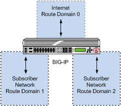
Multiple subscriber networks connecting to Internet servers in Internet Route Domain 0
In the next configuration, multiple subscribers can connect to servers in respective Internet route domains. The BIG-IP system allocates available port blocks from the respective Internet route domain to the corresponding subscriber. Allocated port blocks can differ only by route domain, and use identical address and port ranges; consequently, for this configuration, a service provider must provide a means to distinguish the connections of different route domains, as necessary.
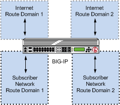
Multiple subscriber networks connecting to Internet servers in separate Internet route domains
PBA log examples
Following are some examples of the elements that comprise a typical Port Block Allocation (PBA) mode log entry.
NAT44 HSL example
PBA log messages include several elements of interest. The following examples show typical log messages, and the table describes common information types.
Jul 23 09:33:42 www.siterequest.com "LSN_PB_ALLOCATED""10.10.10.1""5.5.5.9: 5555-6666"
Jul 23 09:33:42 www.siterequest.com "LSN_PB_RELEASED""10.10.10.1""5.5.5.9: 5555-6666"
Jul 23 09:33:42 www.siterequest.com "LSN_PB_ALLOCATED""10.10.10.1%55""5.5.5.9%22: 5555-6666"
Jul 23 09:33:42 www.siterequest.com "LSN_PB_RELEASED""10.10.10.1%55""5.5.5.9%22: 5555-6666"
Jul 23 10:46:31 www.siterequest.com "LSN_PB_ALLOCATED""2701: :200""5.5.5.9:5555-6666"
Jul 23 10:46:31 www.siterequest.com "LSN_PB_RELEASED""2701: :200""5.5.5.9:5555-6666"
Jul 23 09:36:33 www.siterequest.com "LSN_PB_ALLOCATED""2701: :200%11""5.5.5.9%22:5555-6666"
Jul 23 09:36:33 www.siterequest.com "LSN_PB_RELEASED""2701: :200%11""5.5.5.9%22:5555-6666"
Jul 23 09:36:33 www.siterequest.com "LSN_PB_ALLOCATED""2701: :200""5.5.5.9:5555-6666"
Jul 23 09:36:33 www.siterequest.com "LSN_PB_RELEASED""2701: :200"5.5.5.9:5555-6666"
Jul 23 09:36:33 www.siterequest.com "LSN_PB_ALLOCATED""2701: :200%33""5.5.5.9%22:5555-6666"
Jul 23 09:36:33 www.siterequest.com "LSN_PB_RELEASED""2701: :200%33""5.5.5.9%22:5555-6666"
Jul 23 10:56:13 www.siterequest.com lsn_event="LSN_PB_ALLOCATED",lsn_client="10.10.10.1",lsn_pb="5.5.5.9: 5555-6666"
Jul 23 10:56:13 www.siterequest.com lsn_event="LSN_PB_RELEASED",lsn_client="10.10.10.1",lsn_pb="5.5.5.9: 5555-6666"
Jul 23 10:56:13 www.siterequest.com lsn_event="LSN_PB_ALLOCATED",lsn_client="10.10.10.1%55",lsn_pb="5.5.5.9%22: 5555-6666"
Jul 23 10:56:13 www.siterequest.com lsn_event="LSN_PB_RELEASED",lsn_client="10.10.10.1%55",lsn_pb="5.5.5.9%22: 5555-6666"
Jul 23 10:57:08 www.siterequest.com lsn_event="LSN_PB_ALLOCATED",lsn_dslite_client="2701: :200",lsn_pb="5.5.5.9:5555-6666"
Jul 23 10:57:08 www.siterequest.com lsn_event="LSN_PB_RELEASED",lsn_dslite_client="2701: :200",lsn_pb="5.5.5.9:5555-6666"
Jul 23 10:57:08 www.siterequest.com lsn_event="LSN_PB_ALLOCATED",lsn_dslite_client="2701: :200%11",lsn_pb="5.5.5.9%22:5555-6666"
Jul 23 10:57:08 www.siterequest.com lsn_event="LSN_PB_RELEASED",lsn_dslite_client="2701: :200%11",lsn_pb="5.5.5.9%22:5555-6666"
Jul 23 10:57:08 www.siterequest.com lsn_event="LSN_PB_ALLOCATED",lsn_client="2701: :200",lsn_pb="5.5.5.9:5555-6666"
Jul 23 10:57:08 www.siterequest.com lsn_event="LSN_PB_RELEASED",lsn_client="2701: :200",lsn_pb="5.5.5.9:5555-6666"
Jul 23 10:57:08 www.siterequest.com lsn_event="LSN_PB_ALLOCATED",lsn_client="2701: :200%33",lsn_pb="5.5.5.9%22:5555-6666"
Jul 23 10:57:08 www.siterequest.com lsn_event="LSN_PB_RELEASED",lsn_client="2701: :200%33",lsn_pb="5.5.5.9%22:5555-6666"
| Information Type | Example Value | Description |
|---|---|---|
| Timestamp | Jul 23 10:57:08 | Specifies the time and date that the system logged the event message. |
| Domain name | www.siterequest.com | Specifies the domain name of the client. |
| LSN event | lsn_event="LSN_PB_ALLOCATED"; lsn_event="LSN_PB_RELEASED" | Specifies the allocation or release of the port block. |
| Client address | 10.10.10.1; 10.10.10.1%55; 2701: :200; 2701: :200%33; lsn_client="10.10.10.1"; lsn_client="10.10.10.1%55"; lsn_dslite_client="2701: :200"; lsn_dslite_client="2701: :200%11" | Specifies the address of the client. |
| Port block address | 5.5.5.9; 5.5.5.9%22 | Specifies the address of the port block. |
| Port range start | 5555 | Specifies the start of the port range. |
| Port range end | 6666 | Specifies the end of the port range. |
Task summary
Creating a PBA LSN pool
- The CGNAT module must be provisioned before LSN pools can be configured.
- Before associating a LSN pool with a log publisher, ensure that at least one log publisher exists on the BIG-IP® system.


