Manual Chapter : Configuring ISP Load Balancing

Applies To:

Show Versions Show Versions

BIG-IP LTM

  • 12.1.6, 12.1.5, 12.1.4, 12.1.3, 12.1.2, 12.1.1, 12.1.0
Manual Chapter

Configuring ISP Load Balancing

Overview: ISP load balancing

You might find that as your network grows, or network traffic increases, you require an additional connection to the Internet. You can use this configuration to add an Internet connection to your existing network. The following illustration shows a network configured with two Internet connections.

Illustration of ISP load balancing
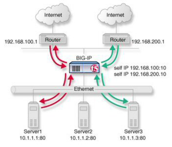
ISP load balancing

ISP load balancing

Task summary for ISP load balancing

There are number of tasks you must perform to implement load balancing for ISPs.

Task list

Creating a load balancing pool

You can a create load balancing pool, which is a logical set of devices, such as web servers, that you group together to receive and process traffic, to efficiently distribute the load on your resources. Using this procedure, create one pool that load balances the content servers, and one pool to load balance the routers.
  1. On the Main tab, click Local Traffic > Pools .
    The Pool List screen opens.
  2. Click Create.
    The New Pool screen opens.
  3. In the Name field, type a unique name for the pool.
  4. For the Health Monitors setting, in the Available list, select a monitor type, and click << to move the monitor to the Active list.
    Tip: Hold the Shift or Ctrl key to select more than one monitor at a time.
  5. From the Load Balancing Method list, select how the system distributes traffic to members of this pool.
    The default is Round Robin.
  6. For the Priority Group Activation setting, specify how to handle priority groups:
    • Select Disabled to disable priority groups. This is the default option.
    • Select Less than, and in the Available Members field type the minimum number of members that must remain available in each priority group in order for traffic to remain confined to that group.
  7. Using the New Members setting, add each resource that you want to include in the pool:
    1. (Optional) In the Node Name field, type a name for the node portion of the pool member.
    2. In the Address field, type an IP address.
    3. In the Service Port field, type a port number, or select a service name from the list.
    4. (Optional) In the Priority field, type a priority number.
    5. Click Add.
  8. Click Repeat and create another pool.
  9. Click Finished.
The load balancing pools appear in the Pools list.

Creating a virtual server for inbound content server traffic

You must create a virtual server to load balance inbound connections. The default pool that you assign as a resource in this procedure is the pool of internal servers.
  1. On the Main tab, click Local Traffic > Virtual Servers .
    The Virtual Server List screen opens.
  2. Click the Create button.
    The New Virtual Server screen opens.
  3. In the Name field, type a unique name for the virtual server.
  4. In the Destination Address/Mask field, type the IP address in CIDR format.
    The supported format is address/prefix, where the prefix length is in bits. For example, an IPv4 address/prefix is 10.0.0.1 or 10.0.0.0/24, and an IPv6 address/prefix is ffe1::0020/64 or 2001:ed8:77b5:2:10:10:100:42/64. When you use an IPv4 address without specifying a prefix, the BIG-IP® system automatically uses a /32 prefix.
    Note: The IP address you type must be available and not in the loopback network.
  5. In the Service Port field, type a port number or select a service name from the Service Port list.
  6. If the traffic to be load balanced is of a certain type, select the profile type that matches the connection type.
    To load balance HTTP traffic, locate the HTTP Profile setting and select http.
  7. In the Resources area of the screen, from the Default Pool list, select the relevant pool name.
  8. Click Finished.
The virtual server is configured to load balance inbound connections to the servers.

Creating a virtual server for outbound traffic for routers

You must create a virtual server to load balance outbound connections. The default pool that you assign as a resource in this procedure is the pool of routers.
  1. On the Main tab, click Local Traffic > Virtual Servers .
    The Virtual Server List screen opens.
  2. Click the Create button.
    The New Virtual Server screen opens.
  3. In the Name field, type a unique name for the virtual server.
  4. In the Destination Address/Mask field, type the IP address in CIDR format.
    The supported format is address/prefix, where the prefix length is in bits. For example, an IPv4 address/prefix is 10.0.0.1 or 10.0.0.0/24, and an IPv6 address/prefix is ffe1::0020/64 or 2001:ed8:77b5:2:10:10:100:42/64. When you use an IPv4 address without specifying a prefix, the BIG-IP® system automatically uses a /32 prefix.
    Note: The IP address you type must be available and not in the loopback network.
  5. In the Resources area of the screen, from the Default Pool list, select the relevant pool name.
  6. Click Finished.
The virtual server is configured to load balance outbound connections to the routers.

Creating self IP addresses an external VLAN

You must assign two self IP addresses to the external VLAN.
  1. On the Main tab, click Network > Self IPs .
  2. Click Create.
    The New Self IP screen opens.
  3. In the IP Address field, type an IP address.
    This IP address should represent the network of the router.
    The system accepts IPv4 and IPv6 addresses.
  4. In the Netmask field, type the network mask for the specified IP address.

    For example, you can type 255.255.255.0.

  5. Select External from the VLAN list.
  6. Click Repeat.
  7. In the IP Address field, type an IPv4 or IPv6 address.
    This IP address should represent the address space of the VLAN that you specify with the VLAN/Tunnel setting.
  8. Click Finished.
    The screen refreshes, and displays the new self IP address.
The self IP address is assigned to the external VLAN.

Enabling SNAT automap for internal and external VLANs

You can configure SNAT automapping on the BIG-IP system for internal and external VLANs.
  1. On the Main tab, click Local Traffic > Address Translation .
    The SNAT List screen displays a list of existing SNATs.
  2. Click Create.
  3. Name the new SNAT.
  4. From the Translation list, select Automap.
  5. For the VLAN / Tunnel List setting, in the Available list, select external and internal, and using the Move button, transfer the VLANs to the Selected list.
  6. Click the Finished button.
SNAT automapping on the BIG-IP system is configured for internal and external VLANs.