Manual Chapter : Configuring Diameter Load Balancing and Message Routing

Applies To:

Show Versions Show Versions

BIG-IP LTM

  • 12.1.6, 12.1.5, 12.1.4, 12.1.3, 12.1.2, 12.1.1, 12.1.0
Manual Chapter

Configuring Diameter Load Balancing and Message Routing

Overview: Diameter message routing

The Diameter protocol provides message-routing functionality that the BIG-IP® system supports in a load-balancing configuration.

Diameter message routing configuration

In a message routing configuration, the BIG-IP system manages requests and responses among peers. The following illustration shows a Diameter routing configuration with requests from Client 1 and Client 2 to servers located in different destination realms, Realm-A and Realm-B.

A Diameter routing configuration

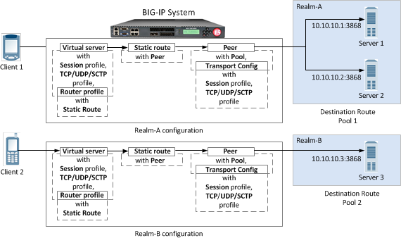
A Diameter message routing configuration

A typical Diameter message routing configuration with two realms involves configuring the following items.

Functionality Description
Pool A pool for each realm directs Diameter traffic to servers.
Session profile A session profile for each realm configures a session as a set of messages between two Diameter nodes on behalf of a user.
Transport configuration An optional transport configuration for each realm defines how the BIG-IP system connects with the servers on your network when routing messages. You can assign a transport configuration to a virtual server or peer, as needed.
Peer Each BIG-IP message-routing peer routes messages to a destination host. In this example, BIG-IP message-routing peers route messages to 10.10.10.1:3868, 10.10.10.2:3868, and 10.10.10.3:3868.
Static Route Each static route specifies a set of peers in a destination realm to use in forwarding messages. In this example, Realm-A includes Peer 1 , and Realm-B includes Peer 2.
Router profile A router profile configures Diameter message routing parameters and static routes to be used by a virtual server in routing Diameter messages.
Virtual server Manages Diameter traffic to and from each realm and pool members.

Task summary

Complete these tasks to configure Diameter message routing on a BIG-IP® system.

Task list

Creating a pool to manage Diameter traffic

In a basic Diameter message routing configuration, you can define a routing pool that contains Diameter servers as its members.
  1. On the Main tab, click Local Traffic > Pools .
    The Pool List screen opens.
  2. Click Create.
    The New Pool screen opens.
  3. In the Name field, type a unique name for the pool.
  4. Using the New Members setting, add each resource that you want to include in the pool:
    1. (Optional) In the Node Name field, type a name for the node portion of the pool member.
    2. In the Address field, type an IP address.
    3. In the Service Port field, type a port number, or select a service name from the list.
    4. (Optional) In the Priority field, type a priority number.
    5. Click Add.
  5. Click Finished.
The pool is configured to manage Diameter servers as pool members.

Creating a Diameter Session profile

You can create a Diameter Session profile to specify protocol parameters, as necessary.
  1. On the Main tab, click Local Traffic > Profiles > Message Routing > Diameter .
    The Diameter session profiles list screen opens.
  2. Click Create.
    The New Diameter Session Profile screen opens.
  3. In the Name field, type a unique name for the diameter session profile.
  4. From the Parent Profile list, select a profile from which the new profile inherits properties.
  5. Add a description.
    1. In the General Properties area, for the Description field, select the check box.
    2. In the Description field, type a description.
  6. For the Settings area, select the Custom check box to enable editing, and specify the following parameters.
    1. In the Handshake Timeout field, type the number of seconds before the handshake to a peer times out.
    2. In the Maximum Watchdog Failures field, type the maximum number of device watchdog failures that the traffic management system can receive before it tears down the connection.
      Note: If the number of device watchdog failures exceeds the specified value, and the Reset on Timeout check box is selected, then the connection will be reset. If the number of device watchdog failures is greater than 3 times the specified value, the connection will be reset, even if the Reset on Timeout check box is cleared.
    3. Select the Reset on Timeout check box to reset the connection when watchdog failures exceed the specified number of maximum watchdog failures.
    4. In the Watchdog Timeout field, type the number of seconds that a client-side or server-side connection can be idle before a device watchdog request (DWR) is sent.
      Note: The default value of 0 prevents sending a DWR.
    5. In the Maximum Message Size field, type the maximum number of bytes allowed for a message.
  7. For the Persistence area, select the Custom check box and specify the following parameters.
    1. From the Persist Type list, select a type of persistence.
      Setting Description
      None Disables persistence.
      AVP Enables persistence as determined by the AVP within the message.
      Custom Enables persistence as determined by a custom key specified within an iRule.
    2. In the Persist AVP field, type an expression for the session-key that identifies the Diameter AVP.
    3. In the Persist Timeout field, type a timeout value for persistence entries in seconds.
  8. For the Rewrite area, select the Custom check box and specify the following parameters.
    1. In the Origin Host Rewrite field, type a value to use in rewriting the Origin-Host AVP on egress.
      Note: This value applies to all Diameter messages and can override specified Capabilities Handshake AVP values.
    2. In the Origin Realm Rewrite field, type a value to use in rewriting the Origin-Realm AVP on egress.
      Note: This value applies to all Diameter messages and can override specified Capabilities Handshake AVP values.
    3. In the Destination Host Rewrite field, type a value to use in rewriting the Destination-Host AVP on egress.
    4. In the Destination Realm Rewrite field, type a value to use in rewriting the Destination-Realm AVP on egress.
  9. For the Capabilities Handshake area, select the Custom check box and specify the following parameters.
    Note: You must configure these settings to initiate Capabilities-Exchange-Request (CER) handshake requests to downstream peers, as well as to provide Capabilities-Exchange-Answer (CEA) responses to upstream peers within Device-Watchdog-Request (DWR), Device-Watchdog-Answer (DWA), Disconnect-Peer-Request (DPR), and Disconnect-Peer-Answer (DPA) messages.
    1. In the Origin Host field, type an identifier for the originating server, for example, siteserver.f5.com.
      If the Origin Host setting is not specified, the BIG-IP system host is used.
    2. In the Origin Realm field, type an identifier for the originating realm, for example, f5.
      If the Origin Realm setting is not specified, the BIG-IP system realm is used.
    3. In the Vendor ID field, type the vendor identification number assigned to the diameter server by the Internet Assigned Numbers Authority (IANA).
      Note: You can use a vendor-specific vendor-id, auth-application-id, or acct-application-id.
    4. In the Product Name field, type a vendor-assigned name for the product.
    5. In the Authentication Application ID field, type the AAA identifier for a specific application.
    6. In the Accounting Application ID field, type the accounting identifier for a specific application.
  10. Click Finished.
The Diameter Session profile is configured to apply protocol parameters, as necessary

Creating a transport config

Before you can create a transport config, you must ensure that at least one Diameter session profile exists in the BIG-IP® system configuration.
Create a transport config to define how the BIG-IP system connects with the servers on your network when routing and load balancing Diameter messages.
  1. On the Main tab, click Local Traffic > Profiles > Message Routing > Diameter .
    The Diameter session profiles list screen opens.
  2. On the menu bar, click Transport Config.
    The Diameter screen opens.
  3. Click Create.
    The New Transport Config screen opens.
  4. In the Name field, type a unique name for the transport configuration.
  5. For the Profiles setting, move both a transport protocol profile (TCP, UDP, or SCTP) and a Diameter session profile from the Available list to the Selected list.
    You can only associate one protocol profile and one session profile with each transport configuration.
  6. For the iRules setting, select an iRule from the Available list, and move it to the Selected list.
  7. In the Source Port field, type the number of the port this transport configuration uses to connect to the servers on your network.
  8. From the Source Address Translation list, select an option to define how this transport configuration implements selective and intelligent source address translation. The default is Auto Map.
    Option Description
    SNAT The system uses the specified SNAT pool for source address translation.
    Auto Map

    The system uses the self IP addresses of BIG-IP as the translation addresses.

    None

    The system does not translate source addresses.

  9. Click Finished.

Creating a peer

In order to create a peer, you must first ensure that at least one transport configuration and one pool exist in the BIG-IP® system configuration.
You create a peer to define how the BIG-IP system connects with the servers on your network, and to which servers the system routes and load balances messages.
  1. On the Main tab, click Local Traffic > Profiles > Message Routing > Diameter .
    The Diameter session profiles list screen opens.
  2. On the menu bar, click Peers.
    The Peers list screen opens.
  3. Click Create.
    The New Peer screen opens.
  4. In the Name field, type a unique name for the peer.
  5. In the Description field, type a description of the peer.
  6. From the Connection Mode list, select an option to specify how connections are distributed to a remote host.
    Option Description
    Per Blade The number of connections are distributed and controlled per blade on a VIPRION® system.
    Per Peer (Default) The number of connections to a remote host is per peer.
    Per TMM The number of connections to a remote host is per TMM on the BIG-IP system.
    Per Client The number of connections to a remote host is per client connection. Responses are delivered to the connection initiating the request. This option is typically used when implementing a firewall, because of its restrictive functionality.
    Note: The configured Connection Mode, Number of Connections, and Ratio settings determine how the BIG-IP system uses connections to pool members in delivering messages.
  7. From the Pool list, select the pool of servers to which the system load balances Diameter messages.
    If you configure only one peer on this BIG-IP system, ensure that you select a pool with only one member.
    Note: If a peer does not specify a pool, the BIG-IP system uses the destination IP address and port of the ingress message's connection. If a peer specifies a pool without pool members, the message is unroutable.
  8. From the Transport Config list, select the transport configuration that defines the egress message routing peer connection.
  9. In the Number of Connections field, type the number of allowed connections between the BIG-IP system and the servers in the selected pool.
  10. In the Ratio field, type the ratio assigned to this peer for use within a static route.
  11. Click Finished.
A peer determines how the BIG-IP system connects with the servers on your network, and to which servers the system routes and load balances messages.

Creating a static route

Before you can create a static route, you must ensure that at least one peer and one virtual server exist in the BIG-IP® system configuration.
You create a static route when you want to route proxiable messages from specific clients to specific domains, and load balance those messages across a group of peers. If the configured attributes of a static route match the attributes in a message, the system forwards the message to a member of the pool associated with one of the peers.
Note: The BIG-IP system can use multiple session profiles in a single routing instance, because a different profile can be associated with each member of a pool.
  1. On the Main tab, click Local Traffic > Profiles > Message Routing > Diameter .
    The Diameter session profiles list screen opens.
  2. On the menu bar, click Static Routes.
    The static routes list screen opens.
  3. Click Create.
    The New Route screen opens.
  4. In the Name field, type a unique name for the static route.
  5. In the Description field, type a description.
  6. In the Application ID field, type the identifier matching the application-id in the Diameter message. A value of 0 matches every application-id.
  7. In the Destination Realm field, type the destination realm matching the Destination-Realm AVP value in the message.
    Note: A blank value routes all destination-realms.
  8. In the Origin Realm field, type the origin realm matching the Origin-Realm AVP value in the message.
    Note: A blank value routes all origin-realms.
  9. From the Virtual Server list, select the virtual server from which the system receives client requests for this static route.
    If you do not select a virtual server, the system uses this static route to route messages originating from any client.
  10. From the Peer Selection Mode list, select an option to specify how the system selects the Peer to route a message to:
    Option Description
    Ratio Peer selection is based on the ratio that is set for each peer in the Selected list.
    Sequential Peer selection is based on the order of the peers in the Selected list.
  11. For the Peers setting, move, from the Available list to the Selected list, the peers that define the servers to which the system load balances or routes messages.
    Note: Entries in the Selected list are not prioritized; consequently, the order of items appearing in the list is not enforced.
  12. Click Finished.
A static route is configured to route messages from specific clients to specific domains.

Creating a Diameter Router profile

You can create a Diameter Router profile to route traffic as specified.
  1. On the Main tab, click Local Traffic > Profiles > Message Routing > Diameter .
    The Diameter session profiles list screen opens.
  2. On the menu bar, click Router Profiles.
    The router profiles list screen opens.
  3. Click Create.
    The New Diameter Router Profile screen opens.
  4. In the Name field, type a unique name for the diameter session profile.
  5. From the Parent Profile list, select a profile from which the new profile inherits properties.
  6. For the Description setting, select the check box at the right, and type a description in the field.
  7. At the top of the Settings area, select the Custom check box.
  8. Select the Use Local Connection check box to specify that connections established by the ingress TMM are preferred to connections that are established by another TMM when selecting an egress connection to a destination peer.
  9. In the Maximum Pending Messages field, type the maximum number of pending messages held while waiting for a connection to a peer to be created.
    Note: If the specified value is reached, any additional messages to the peer will be undeliverable, and held messages are delivered to the peer.
  10. In the Maximum Pending Bytes field, type the maximum number of bytes contained within pending messages that will be held while waiting for a connection to a peer to be created.
    Note: If the specified value is reached, any additional messages to the peer will be undeliverable, and held messages are delivered to the peer.
  11. Optional: For use with connection mirroring, configure the Traffic Group setting:
    1. Clear the Inherit traffic group from current partition / path check box.
    2. From the list, select a traffic group, such as, traffic-group-1
    Important: Changing traffic groups with Connection Mirroring enabled drops all mirrored connections and loses all persistence data. If you change traffic groups, mirroring must restart.
  12. Optional: Select the Connection Mirroring check box.
    Note: For connection mirroring to properly function, this device must be a member of a device group.
  13. In the HA Message Sweeper Interval field, type a value (in milliseconds) for the frequency of the mirrored message sweeper.
  14. In the Transaction Timeout field, type the maximum number of seconds the system allows for a transaction, that is, the time between a request and response.
    Note: When the system receives a provisional response, the timer restarts.
  15. For the Static Routes setting, select a static route from the Available list, and move it to the Selected list.
  16. Click Finished.
The Diameter Router profile is configured to route traffic, as you have specified.

Creating a virtual server to manage Diameter traffic

The final task in configuring Diameter load balancing is to define a virtual server that references the custom Diameter profile and Diameter pool that you created in previous tasks.
Note: The virtual server to which you assign the Diameter profile must be a Standard type of virtual server.
  1. On the Main tab, click Local Traffic > Virtual Servers .
    The Virtual Server List screen opens.
  2. Click the Create button.
    The New Virtual Server screen opens.
  3. In the Name field, type a unique name for the virtual server.
  4. From the Type list, select Message Routing.
  5. In the Destination Address/Mask field, type the IP address in CIDR format.
    The supported format is address/prefix, where the prefix length is in bits. For example, an IPv4 address/prefix is 10.0.0.1 or 10.0.0.0/24, and an IPv6 address/prefix is ffe1::0020/64 or 2001:ed8:77b5:2:10:10:100:42/64. When you use an IPv4 address without specifying a prefix, the BIG-IP® system automatically uses a /32 prefix.
    Note: The IP address you type must be available and not in the loopback network.
  6. In the Service Port field, type 3868.
  7. From the Configuration list, select Advanced.
  8. From the Application Protocol list, select Diameter.
  9. From the Session Profile list, select a Diameter session profile.
    Note: You can specify a different session profile, as needed, when configuring the transport configuration that is assigned to a peer.
  10. From the Router Profile list, select a Diameter router profile.
  11. Click Finished.
The virtual server that references the custom Diameter profile and Diameter pool appears in the Virtual Server list.

About checking Diameter pool member health

You can configure the BIG-IP® system to monitor pool member health using a Diameter monitor. Use a Diameter monitor to check the health of a host with an active Diameter session. The Diameter monitor also monitors a Diameter connection independently of a specific Diameter session and marks a host that had been marked down, but is online again, as available.

Task summary

Perform these tasks to configure health monitors and apply the monitors to a pool:

Creating a custom Diameter monitor

After you create a Diameter profile, you can create a custom Diameter monitor. The purpose of the Diameter monitor is to monitor the health of all servers running the Diameter service.
  1. On the Main tab, click Local Traffic > Monitors .
    The Monitor List screen opens.
  2. Click Create.
    The New Monitor screen opens.
  3. Type a name for the monitor in the Name field.
  4. From the Type list, select Diameter.
    The screen refreshes, and displays the configuration options for the Diameter monitor type.
  5. Configure additional settings based on your network requirements.
  6. Click Finished.

Adding a health monitor to a pool

Add health monitors to a pool when you want the BIG-IP system to monitor the health of the pool members. Repeat this procedure for each desired pool.
  1. On the Main tab, click Local Traffic > Pools .
    The Pool List screen opens.
  2. Click the name of the pool you want to modify.
  3. For the Health Monitors setting, in the Available list, select a monitor type, and click << to move the monitor to the Active list.
    Tip: Hold the Shift or Ctrl key to select more than one monitor at a time.
  4. Click Finished.
The new pool appears in the Pools list.

About viewing Diameter session and router statistics

You can view statistics for Diameter sessions and routes.

Task summary

Viewing Diameter session statistics

Ensure that a Diameter session profile is assigned to at least one virtual server.
When you want to see how the BIG-IP® system is handling Diameter communications, you can view statistics per Diameter session profile.
  1. On the Main tab, click Statistics > Module Statistics > Local Traffic .
    The Local Traffic statistics screen opens.
  2. From the Statistics Type list, select Profiles Summary.
  3. In the Details column for the Diameter Session profile, click View to display detailed statistics about Diameter sessions.

Viewing Diameter router statistics

Ensure that at Diameter router profile is assigned to at least one virtual server.
When you want to see how the BIG-IP® system is handling Diameter message routing, you can view statistics per Diameter router profile.
  1. On the Main tab, click Statistics > Module Statistics > Local Traffic .
    The Local Traffic statistics screen opens.
  2. From the Statistics Type list, select Profiles Summary.
  3. In the Details column for the Diameter Router profile, click View to display detailed statistics about the routing of Diameter messages.