Applies To:
Show Versions
BIG-IP LTM
- 12.1.6, 12.1.5, 12.1.4, 12.1.3, 12.1.2, 12.1.1, 12.1.0
Configuring nPath Routing
Overview: Layer 2 nPath routing
With the Layer 2 nPath routing configuration, you can route outgoing server traffic around the BIG-IP® system directly to an outbound router. This method of traffic management increases outbound throughput because packets do not need to be transmitted to the BIG-IP system for translation and then forwarded to the next hop.
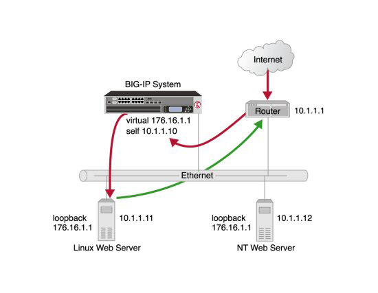
Layer 2 nPath routing
In bypassing the BIG-IP system on the return path, Layer 2 nPath routing departs significantly from a typical load-balancing configuration. In a typical load-balancing configuration, the destination address of the incoming packet is translated from that of the virtual server to that of the server being load balanced to, which then becomes the source address of the returning packet. A default route set to the BIG-IP system then sees to it that packets returning to the originating client return through the BIG-IP system, which translates the source address back to that of the virtual server.
About Layer 2 nPath routing configuration
The Layer 2 nPath routing configuration differs from the typical BIG-IP® load balancing configuration in the following ways:
- The default route on the content servers must be set to the router's internal address (10.1.1.1 in the illustration) rather than to the BIG-IP system's floating self IP address (10.1.1.10). This causes the return packet to bypass the BIG-IP system.
- If you plan to use an nPath configuration for TCP traffic, you must create a Fast L4 profile with the following custom settings:
- Enable the Loose Close setting. When you enable this setting, the TCP protocol flow expires more quickly, after a TCP FIN packet is seen. (A FIN packet indicates the tearing down of a previous connection.)
- Set the TCP Close Timeout setting to the same value as the profile idle timeout if you expect half closes. If not, you can set this value to 5 seconds.
- Because address translation and port translation have been disabled, when the incoming packet arrives at the pool member it is load balanced to the virtual server address (176.16.1.1 in the illustration), not to the address of the server. For the server to respond to that address, that address must be configured on the loopback interface of the server and configured for use with the server software.
Guidelines for UDP timeouts
When you configure nPath for UDP traffic, the BIG-IP® system tracks packets sent between the same source and destination address to the same destination port as a connection. This is necessary to ensure the client requests that are part of a session always go to the same server. Therefore, a UDP connection is really a form of persistence, because UDP is a connectionless protocol.
To calculate the timeout for UDP, estimate the maximum amount of time that a server transmits UDP packets before a packet is sent by the client. In some cases, the server might transmit hundreds of packets over several minutes before ending the session or waiting for a client response.
Guidelines for TCP timeouts
When you configure nPath for TCP traffic, the BIG-IP® system recognizes only the client side of the connection. For example, in the TCP three-way handshake, the BIG-IP system sees the SYN from the client to the server, and does not see the SYN acknowledgment from the server to the client, but does see the acknowledgment of the acknowledgment from the client to the server. The timeout for the connection should match the combined TCP retransmission timeout (RTO) of the client and the node as closely as possible to ensure that all connections are successful.
The maximum initial RTO observed on most UNIX and Windows® systems is approximately 25 seconds. Therefore, a timeout of 51 seconds should adequately cover the worst case. When a TCP session is established, an adaptive timeout is used. In most cases, this results in a faster timeout on the client and node. Only in the event that your clients are on slow, lossy networks would you ever require a higher TCP timeout for established connections.
Task summary
There are several tasks you perform to create a Layer 2 nPath routing configuration.
Task list
Creating a Fast L4 profile
Creating a server pool for nPath routing
Creating a virtual server for Layer 2 nPath routing
Configuring the virtual address on the server loopback interface
Setting the route for inbound traffic
For inbound traffic, you must define a route through the BIG-IP® system self IP address to the virtual server. In the example, this route is 176.16.1.1, with the external self IP address 10.1.1.10 as the gateway.
For information about how to define this route, please refer to the documentation provided with your router.


