Applies To:
Show Versions
BIG-IP AAM
- 13.1.5, 13.1.4, 13.1.3, 13.1.1, 13.1.0
BIG-IP APM
- 13.1.5, 13.1.4, 13.1.3, 13.1.1, 13.1.0
BIG-IP Link Controller
- 13.1.5, 13.1.4, 13.1.3, 13.1.1, 13.1.0
BIG-IP Analytics
- 13.1.5, 13.1.4, 13.1.3, 13.1.1, 13.1.0
BIG-IP LTM
- 13.1.5, 13.1.4, 13.1.3, 13.1.1, 13.1.0
BIG-IP AFM
- 13.1.5, 13.1.4, 13.1.3, 13.1.1, 13.1.0
BIG-IP PEM
- 13.1.5, 13.1.4, 13.1.3, 13.1.1, 13.1.0
BIG-IP DNS
- 13.1.5, 13.1.4, 13.1.3, 13.1.1, 13.1.0
BIG-IP ASM
- 13.1.5, 13.1.4, 13.1.3, 13.1.1, 13.1.0
Overview: A simple intranet configuration
The simple intranet implementation is commonly found in a corporate intranet (see the following illustration). In this implementation, the BIG-IP® system performs load balancing for several different types of connection requests:
- HTTP connections to the company's intranet web site. The BIG-IP system load balances the two web servers that host the corporate intranet web site, Corporate.main.net.
- HTTP connections to Internet content. These are handled through a pair of cache servers that are also load balanced by the BIG-IP system.
- Non-HTTP connections to the Internet.
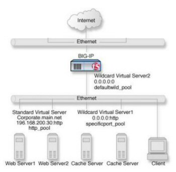
Non-intranet connections
As the illustration shows, the non-intranet connections are handled by wildcard virtual servers; that is, servers with the IP address 0.0.0.0. The wildcard virtual server that is handling traffic to the cache servers is port specific, specifying port 80 for HTTP requests. As a result, all HTTP requests not matching an IP address on the intranet are directed to the cache server. The wildcard virtual server handling non-HTTP requests is a default wildcard server. A default wildcard virtual server is one that uses only port 0. This makes it a catch-all match for outgoing traffic that does not match any standard virtual server or any port-specific wildcard virtual server.
Task summary
To create this configuration, you need to complete these tasks.


