Manual Chapter : Platform Maintenance

Applies To:

Show Versions Show Versions
Manual Chapter

Platform Maintenance

About maintaining the platform

The VIPRION® 2400 platform contains several components that you can replace individually without exchanging the entire system. This platform contains these replaceable components:

  • AC power supply
  • DC power supply
  • Fan tray
  • Storage drive assembly
    Note: Applies only to the B2100 blade with hard disk drive (HDD).
  • Blades

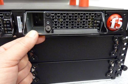
About AC power supplies

The VIPRION® 2400 platform supports one to two hot swappable AC power supplies. The power supplies are auto-ranging from 100-127VAC to 200-240VAC input.

The platform supports power redundancy, which ensures that the system is unaffected if a single power supply fails in a system containing more than one power supply.

Partially-removed power supply

A power supply partially removed from the platform

CAUTION:
Running without all power supplies installed in the platform can affect cooling and electromagnetic interference (EMI). If a power supply fails, you can leave it installed in the chassis and remove the power cord until you receive a replacement supply; the system, however, will continue to log errors.
CAUTION:
The power socket outlet should be installed near the equipment and easily accessible.
Important: This product is sensitive to electrostatic discharge (ESD). F5® recommends that you use proper ESD grounding procedures and equipment when you install or maintain the unit.
Note: Depending on the model and revision type of the power supply, you might need either a Phillips or a slotted screwdriver to replace the power supply.

Removing a power supply

Before you can replace a power supply, you must remove the existing supply from the chassis, if one is installed.
Important: If the chassis has at least one blade operating and you would like uninterrupted operation, make sure that one of the power supplies remains installed and operational during the replacement process.
  1. On the front of the chassis, locate the power supplies.
  2. Disconnect power from the power supply that you would like to remove.
    Note: When you face the front of the chassis, power supply 1 is on the left, and power supply 2 is on the right.
  3. Loosen the captive screw on the power supply eject lever with a #1 Phillips screwdriver, if necessary.
  4. Raise the power supply eject lever.

    Raise poower supply eject lever
  5. Grasp the lever and pull straight toward you to eject the power supply from the power supply bay.

Installing a power supply

If a power supply is already installed in the bay where you are installing the replacement supply, disconnect power from the power supply prior to removing the supply. When you face the front of the chassis, power supply 1 is on the left, and power supply 2 is on the right.
You can add or replace a power supply as part of routine maintenance or in the event of a power supply failure.
Important: If the chassis has at least one blade operating and you would like uninterrupted operation, make sure that one of the power supplies is installed and operating during the replacement process.
  1. Remove the existing supply, if one is installed.
  2. Slide the new power supply into the empty power supply bay.
  3. Lower the power supply eject lever to fully seat the power supply in its bay.
  4. Secure the power supply in its bay by tightening the screw in the middle of the power supply eject lever.
    Note: The screw that holds the ejector handle in place is captive and cannot be removed from the assembly.
After you install the power supply, you can apply power to it.

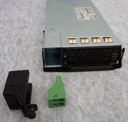
About DC power supplies

The VIPRION® 2400 platform supports up to two hot swappable DC power supplies.

The platform supports power redundancy, which ensures that the system is unaffected if a single power supply fails in a system containing more than one power supply. The DC power supply includes a DC input connector, which is composed of a DC lock assembly and a DC plug. Connect the wires from the DC power source to the DC input connector, and then insert the connector into the DC power supply.

The DC power supply does not have an on/off switch. You can control the power from the rack switch or the DC power source.

CAUTION:
Before installing a DC power supply, be sure that the DC power source for the rack is powered off.
CAUTION:
Running without all power supplies installed in the platform can affect cooling and electromagnetic interference (EMI). If a power supply fails, you can leave it installed in the chassis and remove power from the power supply until you receive a replacement supply; the system, however, will continue to log errors.
CAUTION:
Before you begin to work with one of these platforms, refer to the DC-powered equipment environmental warnings for this platform and review any safety requirements for the facilities where the DC-powered platforms will be installed.
Important: This product is sensitive to electrostatic discharge (ESD). F5® recommends that you use proper ESD grounding procedures and equipment when you install or maintain the unit.
Important: The platform must be installed in a RESTRICTED ACCESS LOCATION, such as a central office or customer premises environment.
Note: All copper grounding cable must meet all appropriate safety standards and local electric codes.
Note: You should coat bare conductors with an appropriate antioxidant compound before you make crimp connections. You should bring all unplated connectors, braided strap, and bus bars to a bright finish and then coat them with an antioxidant before you connect them.
Note: The platform must be grounded to a common bonding network (CBN).
Note: The battery return terminals on the platform are in an isolated DC return (DC-I) configuration.

Removing a power supply

Before you can replace a power supply, you must remove the existing supply from the chassis, if one is installed.
Important: If the chassis has at least one blade operating and you would like uninterrupted operation, make sure that one of the power supplies remains installed and operational during the replacement process.
  1. On the front of the chassis, locate the power supplies.
  2. Disconnect power from the power supply that you would like to remove.
    Note: When you face the front of the chassis, power supply 1 is on the left, and power supply 2 is on the right.
  3. Loosen the captive screw on the power supply eject lever with a #1 Phillips screwdriver, if necessary.
  4. Raise the power supply eject lever.

    Raise poower supply eject lever
  5. Grasp the lever and pull straight toward you to eject the power supply from the power supply bay.

Installing a DC power supply

If a power supply is already installed in the bay where you are installing the replacement supply, disconnect the DC power for the power supply prior to removing the supply. When you face the front of the chassis, power supply 1 is on the left, and power supply 2 is on the right.
You can add or replace a DC power supply as part of routine maintenance or in the event of a power supply failure.
Important: If the chassis has at least one blade operating and you would like uninterrupted operation, make sure that one of the power supplies remains installed and operational during the replacement process.
  1. Remove the existing supply, if one is installed.
  2. Slide the new DC power supply into the empty power supply bay.
    Insert dc power supply
  3. Lower the power supply eject lever to fully seat the power supply in its bay.
  4. Secure the power supply by tightening the captive screw on the power supply eject lever.
    Note: The screw that holds the ejector handle in place is captive and cannot be removed from the assembly.

Wiring the DC connector

You will need these components to wire the DC power supply:

  • Wire stripping tool
  • Two 6 AWG copper wires long enough to reach from the platform to the DC power source
The DC power supply for the VIPRION® 2400 platform includes the components needed to assemble the DC connector: a DC lock assembly and a DC plug.
DC power supply and components

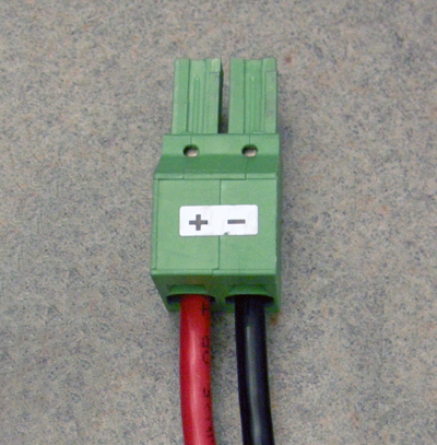
VIPRION 2400 DC power supply, lock assembly, and plug

  1. Use the wire stripping tool to remove 3/8 inch (9.56 mm) of insulation from the end of each 6 AWG wire.
    Important: Be sure to remove the appropriate amount of insulation from each wire. If you remove too much insulation, exposed wire protruding from the DC plug can create an electrical hazard. If you do not remove enough insulation, the wire might not make proper contact with the terminal.
  2. Thread the exposed conductor ends of the wires through the opening in the lock assembly.
  3. Insert the exposed red (+) and black (-) conductors into the appropriate connectors on the DC plug.
    Insert a small flat-head screwdriver into the corresponding release hole on the DC plug to allow the conductor to be freely inserted into the contact opening.

    Example of wired DC plug
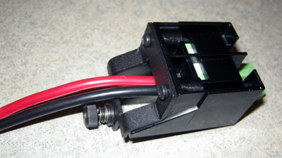
  4. Snap the plug into the lock assembly.

    Wired DC plug and lock assembly

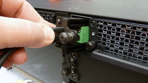
Connecting DC power to the platform

Important: Be sure that the DC power source is off and the ground lug is connected to the ground terminal before you connect the platform to the DC power source.
After you have assembled the DC input connector, you can connect the platform to the DC power source. When you connect the DC power source, you should also follow the safety requirements defined for your network operations center (NOC).
  1. Plug the assembled DC input connector into the outlet of the DC power supply and press firmly until it is fully seated.
    If the connector does not readily insert into the power supply, you might need to manually align it.
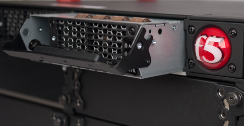
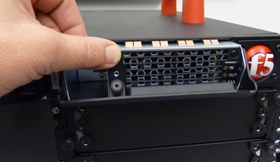
    Inserting DC input connector
  2. Secure the DC input connector to the power supply by tightening the captive screw clockwise until it is secured to the power supply completely.
    Note: The top screw secures the DC input connector to the power supply, and the bottom screw secures the power supply to the chassis.
  3. Connect the DC power cord to an approved power source.
    For more information about voltage input requirements, see Chassis hardware specifications.
  4. Repeat this process for each power supply in the chassis.
  5. Guide the power cables through the cable routing brackets.
  6. Attach the cable management covers to the cable routing brackets by using a #2 Phillips screwdriver, if necessary.
  7. Power on the DC power source.
    The system begins to boot.

About the fan tray

The VIPRION® 2400 platform has a removable fan tray that is designed to maintain airflow throughout the chassis. You can change or replace the fan tray as part of the routine maintenance of the unit, or in the event of a fan failure. The fans in the fan tray run constantly while the unit is on. Over time, the fans can wear out, requiring you to replace the fan tray.

Important: This product is sensitive to electrostatic discharge (ESD). F5® recommends that you use proper ESD grounding procedures and equipment when you install or maintain the unit.
An example of a fan tray in a platform

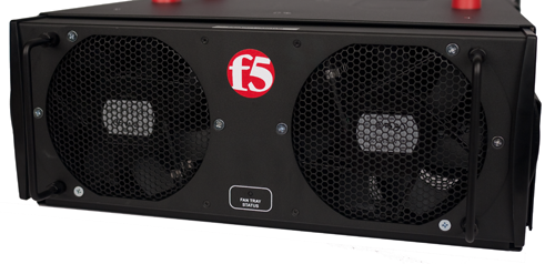
Fan tray in the platform

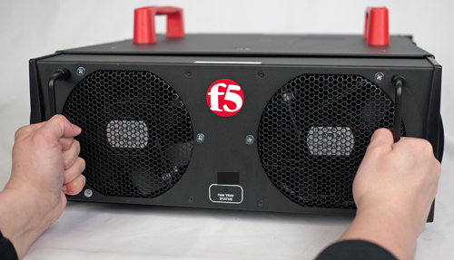
Replacing the fan tray

You can replace the fan tray as part of routine maintenance or in the event of a fan tray failure. You do not need special tools to replace the fan tray. You do not need to power down the unit when replacing the fan tray; however, do not leave the unit operating without a fan tray for longer than 30 seconds.
CAUTION:
Operating the unit without a fan tray for more than 30 seconds might cause permanent damage.
  1. Stand at the back of the platform and locate the ejector handles on the left and right sides of the fan tray.
  2. Extend the fan tray handles and remove the fan tray from the chassis by pulling straight toward you.
    Removing the fan tray
  3. Place the new fan tray into the fan tray bay.
  4. Push the fan tray into the chassis until it is seated firmly in the fan tray bay.
    When seated, the fan tray automatically powers up and begins circulating air through the chassis.
    Important: Use only the fan tray handles to seat the fan tray in the chassis. Using the edges of the fan tray could result in pinched fingers.

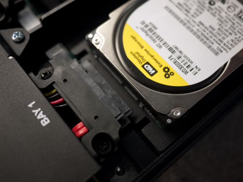
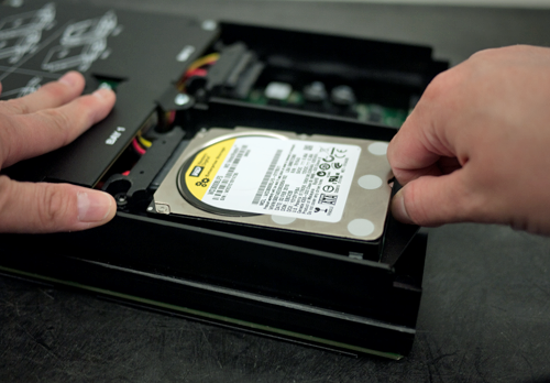
About the storage drive assembly

By default, VIPRION® B2000 Series blades contain one storage drive assembly that contains either one hard disk drive (HDD) or one solid-state drive (SSD).

Important: This product is sensitive to electrostatic discharge (ESD). F5® recommends that you use proper ESD grounding procedures and equipment when you install or maintain the unit.

Replacing a storage drive assembly

You can change or replace a storage assembly that contains a storage drive (hard disk drive or solid-state drive) in a VIPRION® B2000 Series blade as part of the routine maintenance of the unit or in the event of a drive failure.
  1. Remove the blade from the chassis that contains the drive assembly to be replaced.
  2. Remove the existing drive assembly, if one is installed:
    1. Loosen the drive assembly screw by turning it counterclockwise with a Phillips screwdriver, if necessary.
      Note: The screw that holds the ejector handle in place is captive and cannot be removed from the assembly.
    2. Grasp the screw, lift the drive assembly slightly, and then rock the connector gently from side-to-side as you pull to remove the hard drive assembly from the blade.
    Removing old drive
  3. Slide the new drive assembly into the bay.
    Be sure to place the bottom of the assembly under the cable connectors.
    Inserting new drive
  4. Tighten the screw into place.
    The drive assembly is connected to the system when you tighten the screw completely.
  5. Place the blade back into the chassis.