Applies To:
Show Versions
BIG-IP AAM
- 13.1.1, 13.1.0, 13.0.1, 13.0.0, 12.1.4, 12.1.3, 12.1.2, 12.1.1, 12.1.0, 11.6.4, 11.6.3, 11.6.2, 11.6.1, 11.6.0
BIG-IP APM
- 15.1.0, 15.0.1, 15.0.0, 14.1.2, 14.1.0, 14.0.1, 14.0.0, 13.1.3, 13.1.1, 13.1.0, 13.0.1, 13.0.0, 12.1.4, 12.1.3, 12.1.2, 12.1.1, 12.1.0, 11.6.4, 11.6.3, 11.6.2, 11.6.1, 11.6.0
BIG-IP GTM
- 11.6.4, 11.6.3, 11.6.2, 11.6.1, 11.6.0
BIG-IP Analytics
- 15.1.0, 15.0.1, 15.0.0, 14.1.2, 14.1.0, 14.0.1, 14.0.0, 13.1.3, 13.1.1, 13.1.0, 13.0.1, 13.0.0, 12.1.4, 12.1.3, 12.1.2, 12.1.1, 12.1.0, 11.6.4, 11.6.3, 11.6.2, 11.6.1, 11.6.0
BIG-IP Link Controller
- 15.1.0, 15.0.1, 15.0.0, 14.1.2, 14.1.0, 14.0.1, 14.0.0, 13.1.3, 13.1.1, 13.1.0, 13.0.1, 13.0.0, 12.1.4, 12.1.3, 12.1.2, 12.1.1, 12.1.0, 11.6.4, 11.6.3, 11.6.2, 11.6.1, 11.6.0
BIG-IP LTM
- 15.1.0, 15.0.1, 15.0.0, 14.1.2, 14.1.0, 14.0.1, 14.0.0, 13.1.3, 13.1.1, 13.1.0, 13.0.1, 13.0.0, 12.1.4, 12.1.3, 12.1.2, 12.1.1, 12.1.0, 11.6.4, 11.6.3, 11.6.2, 11.6.1, 11.6.0
BIG-IP AFM
- 15.1.0, 15.0.1, 15.0.0, 14.1.2, 14.1.0, 14.0.1, 14.0.0, 13.1.3, 13.1.1, 13.1.0, 13.0.1, 13.0.0, 12.1.4, 12.1.3, 12.1.2, 12.1.1, 12.1.0, 11.6.4, 11.6.3, 11.6.2, 11.6.1, 11.6.0
BIG-IP PEM
- 15.1.0, 15.0.1, 15.0.0, 14.1.2, 14.1.0, 14.0.1, 14.0.0, 13.1.3, 13.1.1, 13.1.0, 13.0.1, 13.0.0, 12.1.4, 12.1.3, 12.1.2, 12.1.1, 12.1.0, 11.6.4, 11.6.3, 11.6.2, 11.6.1, 11.6.0
BIG-IP DNS
- 15.1.0, 15.0.1, 15.0.0, 14.1.2, 14.1.0, 14.0.1, 14.0.0, 13.1.3, 13.1.1, 13.1.0, 13.0.1, 13.0.0, 12.1.4, 12.1.3, 12.1.2, 12.1.1, 12.1.0
BIG-IP ASM
- 15.1.0, 15.0.1, 15.0.0, 14.1.2, 14.1.0, 14.0.1, 14.0.0, 13.1.3, 13.1.1, 13.1.0, 13.0.1, 13.0.0, 12.1.4, 12.1.3, 12.1.2, 12.1.1, 12.1.0, 11.6.4, 11.6.3, 11.6.2, 11.6.1, 11.6.0
Platform Maintenance
About maintaining the platform
The 12000 Series platform contains several components that you can replace individually without exchanging the entire system. This platform contains these replaceable components:
- AC power supply
- DC power supply
- Fan tray
- Hard drive
About AC power supplies
BIG-IP® platforms can support up to two AC power supplies. Some platforms come with only one power supply by default. You can hot swap power supplies without powering down the system if there are two installed and one remains installed and operational during the replacement process.
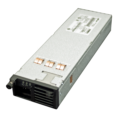
The 850W AC power supply
The platform supports power redundancy, which ensures that the system is unaffected if a single power supply fails in a system containing more than one power supply.
Installing an AC power supply
About DC power supplies
BIG-IP® platforms can support up to two DC power supplies. Some platforms come with only one power supply by default. You can hot swap power supplies without powering down the system if there are two installed and one remains installed and operational during the replacement process. The DC power supply does not have an on/off switch. You can control the power from the rack switch or the DC power source.
The DC power supply includes a DC terminal block that connects the power supply to the DC power source.
The platform supports power redundancy, which ensures that the system is unaffected if a single power supply fails in a system containing more than one power supply.
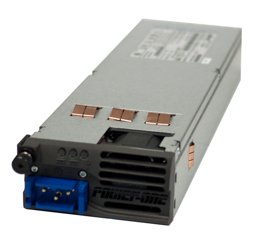
The 850W DC power supply
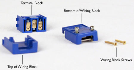
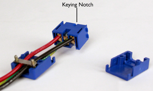
DC terminal block components
Wiring the DC power supply terminal block
- Wire stripping tool
- Small Phillips screwdriver
- Small flat-head screwdriver
-
Thread the wires through the bottom of the terminal block, with the positive
DC wire (typically red) on the left, the chassis ground wire in the middle, and
the negative DC wire (typically black) on the right.
Note the orientation of the keying notch on the terminal block. When the keying notch is up, the positive terminal is on the left.
-
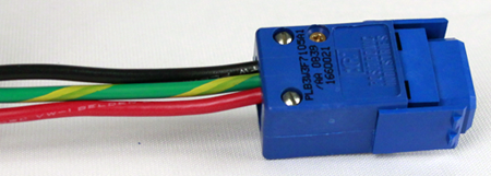
Insert the two gold screws that are provided with the DC power supply kit into
the top and bottom of the terminal block, and then use a Phillips screwdriver
to secure the two halves.
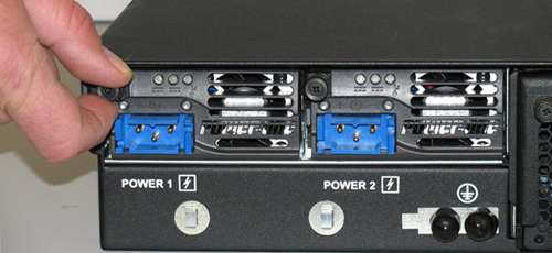
Installing a DC power supply
-
Remove the existing AC or DC power supply, if one is installed.
-
Loosen the power supply screw by turning it
counterclockwise with an appropriate screwdriver, if necessary.
Note: The screw that holds the ejector handle in place is captive and cannot be removed from the assembly.
-
Grasp the ejector handle and rotate it downward to eject
the power supply from the system.
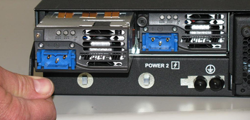
-
Loosen the power supply screw by turning it
counterclockwise with an appropriate screwdriver, if necessary.
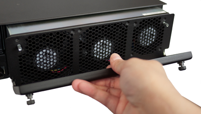
About the fan tray
The BIG-IP® 12000 Series platform has a removable fan tray that is designed to maintain airflow throughout the chassis. You can change or replace the fan tray as part of the routine maintenance of the unit, or in the event of a fan failure. The fans in the fan tray run constantly while the unit is powered on. Over time, the fans can wear out, requiring you to replace the fan tray.
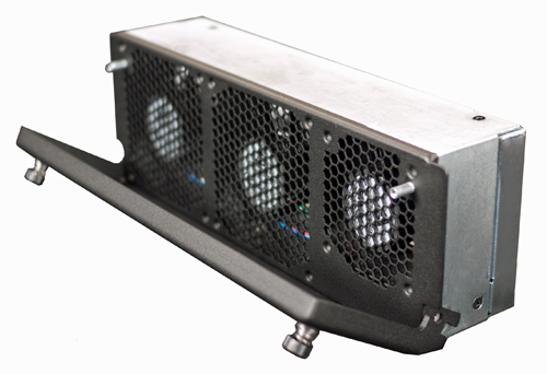
The fan tray
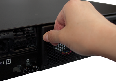
Replacing the fan tray
-
Loosen the fan tray screws by turning them counterclockwise with a
Phillips screwdriver, if necessary.
Note: The screws that hold the ejector handle in place are captive and cannot be removed from the assembly.
-
Grasp the ejector handle and rotate it downward to eject the fan tray
from the system.
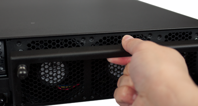
-
Remove the fan tray from the system by pulling straight toward
you.