Manual Chapter : Web Hosting Multiple Customers Using an External Switch

Applies To:

Show Versions Show Versions

BIG-IP AAM

  • 11.6.5, 11.6.4, 11.6.3, 11.6.2, 11.6.1

BIG-IP APM

  • 11.6.5, 11.6.4, 11.6.3, 11.6.2, 11.6.1

BIG-IP GTM

  • 11.6.5, 11.6.4, 11.6.3, 11.6.2, 11.6.1

BIG-IP Analytics

  • 11.6.5, 11.6.4, 11.6.3, 11.6.2, 11.6.1

BIG-IP Link Controller

  • 11.6.5, 11.6.4, 11.6.3, 11.6.2, 11.6.1

BIG-IP LTM

  • 11.6.5, 11.6.4, 11.6.3, 11.6.2, 11.6.1

BIG-IP PEM

  • 11.6.5, 11.6.4, 11.6.3, 11.6.2, 11.6.1

BIG-IP AFM

  • 11.6.5, 11.6.4, 11.6.3, 11.6.2, 11.6.1

BIG-IP ASM

  • 11.6.5, 11.6.4, 11.6.3, 11.6.2, 11.6.1
Manual Chapter

Web Hosting Multiple Customers Using an External Switch

Overview: Web hosting multiple customers using an external switch

You can use the BIG-IP® system to provide hosting services, including application delivery, for multiple customers.

To host multiple web customers, you can incorporate an external switch into the configurations. In this illustration, the BIG-IP system has an interface (5.1) assigned to three VLANs on a network. The three VLANs are vlanA, vlanB, and vlanB. Interface 5.1 processes traffic for all three VLANs. Note that each VLAN contains two servers, and serves a specific customer.

Tip: An alternate way to implement web hosting for multiple customers is to use the route domains feature.

Illustration for hosting multiple customers using an external switch

hosting multiple customers using an external switch

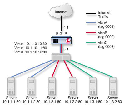
Hosting multiple customers using an external switch

Task summary for hosting multiple customers

Perform these tasks to host multiple customers using an external switch.

Task list

Creating a VLAN with a tagged interface

When you create a VLAN with tagged interfaces, each of the specified interfaces can process traffic destined for that VLAN.
  1. On the Main tab, click Network > VLANs .
    The VLAN List screen opens.
  2. Click Create.
    The New VLAN screen opens.
  3. In the Name field, type a unique name for the VLAN.
  4. In the Tag field, type a numeric tag, from 1-4094, for the VLAN, or leave the field blank if you want the BIG-IP system to automatically assign a VLAN tag.
    The VLAN tag identifies the traffic from hosts in the associated VLAN.
  5. For the Interfaces setting:
    1. From the Interface list, select an interface number.
    2. From the Tagging list, select Tagged.
    3. Click Add.
  6. If you want the system to verify that the return route to an initial packet is the same VLAN from which the packet originated, select the Source Check check box.
  7. In the MTU field, retain the default number of bytes (1500).
  8. From the Configuration list, select Advanced.
  9. If you want to base redundant-system failover on VLAN-related events, select the Fail-safe check box.
  10. From the Auto Last Hop list, select a value.
  11. From the CMP Hash list, select a value.
  12. To enable the DAG Round Robin setting, select the check box.
  13. Click Finished.
    The screen refreshes, and displays the new VLAN in the list.
The new VLAN appears in the VLAN list.

Creating a load balancing pool

You can create a load balancing pool (a logical set of devices such as web servers that you group together to receive and process traffic) to efficiently distribute the load on your server resources.
Note: You must create the pool before you create the corresponding virtual server.
  1. On the Main tab, click Local Traffic > Pools .
    The Pool List screen opens.
  2. Click Create.
    The New Pool screen opens.
  3. In the Name field, type a unique name for the pool.
  4. For the Health Monitors setting, in the Available list, select a monitor type, and click << to move the monitor to the Active list.
    Tip: Hold the Shift or Ctrl key to select more than one monitor at a time.
  5. From the Load Balancing Method list, select how the system distributes traffic to members of this pool.
    The default is Round Robin.
  6. For the Priority Group Activation setting, specify how to handle priority groups:
    • Select Disabled to disable priority groups. This is the default option.
    • Select Less than, and in the Available Members field type the minimum number of members that must remain available in each priority group in order for traffic to remain confined to that group.
  7. Using the New Members setting, add each resource that you want to include in the pool:
    1. In the Node Name field, type a name for the node portion of the pool member.
      This step is optional.
    2. In the Address field, type an IP address.
    3. In the Service Port field, type a port number, or select a service name from the list.
    4. In the Priority field, type a priority number.
      This step is optional.
    5. Click Add.
  8. Click Finished.
The load balancing pool appears in the Pools list.

Creating a virtual server for HTTP traffic

This task creates a destination IP address for application traffic. As part of this task, you must assign the relevant pool to the virtual server.
  1. On the Main tab, click Local Traffic > Virtual Servers .
    The Virtual Server List screen opens.
  2. Click the Create button.
    The New Virtual Server screen opens.
  3. In the Name field, type a unique name for the virtual server.
  4. In the Destination Address field, type the IP address in CIDR format.
    The supported format is address/prefix, where the prefix length is in bits. For example, an IPv4 address/prefix is 10.0.0.1 or 10.0.0.0/24, and an IPv6 address/prefix is ffe1::0020/64 or 2001:ed8:77b5:2:10:10:100:42/64. When you use an IPv4 address without specifying a prefix, the BIG-IP® system automatically uses a /32 prefix.
    Note: The IP address you type must be available and not in the loopback network.
  5. In the Service Port field, type 80, or select HTTP from the list.
  6. From the HTTP Profile list, select http.
  7. In the Resources area of the screen, from the Default Pool list, select the relevant pool name.
  8. Click Finished.
You now have a virtual server to use as a destination address for application traffic.