Manual Chapter : Using Link Aggregation with Tagged VLANs for a Two-network Topology

Applies To:

Show Versions Show Versions

BIG-IP AAM

  • 11.6.5, 11.6.4, 11.6.3, 11.6.2, 11.6.1

BIG-IP APM

  • 11.6.5, 11.6.4, 11.6.3, 11.6.2, 11.6.1

BIG-IP GTM

  • 11.6.5, 11.6.4, 11.6.3, 11.6.2, 11.6.1

BIG-IP Analytics

  • 11.6.5, 11.6.4, 11.6.3, 11.6.2, 11.6.1

BIG-IP Link Controller

  • 11.6.5, 11.6.4, 11.6.3, 11.6.2, 11.6.1

BIG-IP LTM

  • 11.6.5, 11.6.4, 11.6.3, 11.6.2, 11.6.1

BIG-IP PEM

  • 11.6.5, 11.6.4, 11.6.3, 11.6.2, 11.6.1

BIG-IP AFM

  • 11.6.5, 11.6.4, 11.6.3, 11.6.2, 11.6.1

BIG-IP ASM

  • 11.6.5, 11.6.4, 11.6.3, 11.6.2, 11.6.1
Manual Chapter

Using Link Aggregation with Tagged VLANs for a Two-network Topology

Overview: Configuring link aggregation of two interfaces using tagged VLANs on two networks

You can use the BIG-IP® system in an aggregated two-interface load balancing topology. Link aggregation is the process of combining multiple links so that the links function as a single link with higher bandwidth. Aggregating multiple interfaces into a trunk to create a link has the following advantages:

  • Link aggregation increases the bandwidth of the individual network interface cards (NICs) in an additive manner.
  • If one link goes down, the other link can handle the traffic by itself.

Link aggregation occurs when you create a trunk. A trunk is a combination of two or more interfaces and cables configured as one link.

The examples in this implementation show a trunk that includes two tagged interfaces aggregated together. A tagged interface is an interface that is configured to process traffic for multiple VLANs. A VLAN tag identifies the specific VLAN and allows traffic to be passed through that specific VLAN. To cause traffic for multiple VLANs to be passed through a single trunk, you must assign the same trunk to each VLAN.

In the examples, we create a trunk (trunk1) that includes two interfaces, 1.1 and 1.2, and then assign trunk1 as a tagged interface to both VLAN external and VLAN internal. One network is connected to VLAN external, and a separate network is connected to VLAN internal. Consequently, inbound and outbound traffic passing between the BIG-IP system and the vendor switch can use either interface. For example, traffic destined for VLAN externall can pass through either interface, 1.1 or 1.2.

Illustration of link aggregation for a two-network topology

link aggregation for a two-network topology

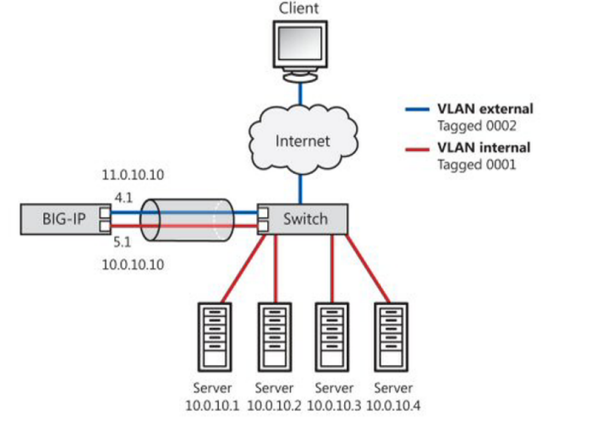
Link aggregation for a two-network topology

Task summary

Perform the following tasks to configure two interfaces (tagged VLANs) to function as a single link with higher bandwidth. In this implementation, each tagged VLAN is on a separate network.

Task list

Creating a trunk

You create a trunk on the BIG-IP® system so that the system can then aggregate the links to enhance bandwidth and ensure link availability.
  1. On the Main tab, click Network > Trunks .
    The Trunk List screen opens.
  2. Click Create.
  3. Name the trunk.
  4. For the Interfaces setting, in the Available field, select an interface, and using the Move button, move the interface to the Members field. Repeat this action for each interface that you want to include in the trunk.
    Trunk members must be untagged interfaces and cannot belong to another trunk. Therefore, only untagged interfaces that do not belong to another trunk appear in the Available list.
  5. Select the LACP check box.
  6. Click Finished.
After you create a trunk, the BIG-IP system aggregates the links to enhance bandwidth and prevent interruption in service.

Adding a tagged interface to a VLAN

After you aggregate the links, you assign the trunk to the VLAN as a tagged interface.
  1. On the Main tab, click Network > VLANs .
    The VLAN List screen opens.
  2. For the Interfaces setting:
    1. From the Interface list, select the trunk name.
    2. From the Tagging list, select Tagged.
    3. Click Add.
The trunk is assigned to the external and internal VLAN as a tagged interface.

Creating a load balancing pool

You can create a load balancing pool (a logical set of devices such as web servers that you group together to receive and process traffic) to efficiently distribute the load on your server resources.
Note: You must create the pool before you create the corresponding virtual server.
  1. On the Main tab, click Local Traffic > Pools .
    The Pool List screen opens.
  2. Click Create.
    The New Pool screen opens.
  3. In the Name field, type a unique name for the pool.
  4. For the Health Monitors setting, in the Available list, select a monitor type, and click << to move the monitor to the Active list.
    Tip: Hold the Shift or Ctrl key to select more than one monitor at a time.
  5. From the Load Balancing Method list, select how the system distributes traffic to members of this pool.
    The default is Round Robin.
  6. For the Priority Group Activation setting, specify how to handle priority groups:
    • Select Disabled to disable priority groups. This is the default option.
    • Select Less than, and in the Available Members field type the minimum number of members that must remain available in each priority group in order for traffic to remain confined to that group.
  7. Using the New Members setting, add each resource that you want to include in the pool:
    1. In the Node Name field, type a name for the node portion of the pool member.
      This step is optional.
    2. In the Address field, type an IP address.
    3. In the Service Port field, type a port number, or select a service name from the list.
    4. In the Priority field, type a priority number.
      This step is optional.
    5. Click Add.
  8. Click Finished.
The load balancing pool appears in the Pools list.

Creating a virtual server with source address affinity persistence

A virtual server represents a destination IP address for application traffic.
  1. On the Main tab, click Local Traffic > Virtual Servers .
    The Virtual Server List screen opens.
  2. Click the Create button.
    The New Virtual Server screen opens.
  3. In the Name field, type a unique name for the virtual server.
  4. For the Destination setting, in the Address field, type the IP address you want to use for the virtual server.
    The IP address you type must be available and not in the loopback network.
  5. In the Service Port field, type a port number or select a service name from the Service Port list.
  6. Locate the relevant profile type for the traffic being managed, and either retain the default value or select a custom profile name.
  7. In the Resources area of the screen, from the Default Pool list, select the relevant pool name.
  8. For the Default Persistence Profile setting, select source_addr.
    This implements simple persistence, using the default source address affinity profile.
A client system now has a destination IP address on the BIG-IP system.