Applies To:
Show Versions
BIG-IP AAM
- 12.1.4, 12.1.3, 12.1.2, 12.1.1, 12.1.0
BIG-IP APM
- 12.1.6, 12.1.5, 12.1.4, 12.1.3, 12.1.2, 12.1.1, 12.1.0
BIG-IP Analytics
- 12.1.6, 12.1.5, 12.1.4, 12.1.3, 12.1.2, 12.1.1, 12.1.0
BIG-IP Link Controller
- 12.1.6, 12.1.5, 12.1.4, 12.1.3, 12.1.2, 12.1.1, 12.1.0
BIG-IP LTM
- 12.1.6, 12.1.5, 12.1.4, 12.1.3, 12.1.2, 12.1.1, 12.1.0
BIG-IP AFM
- 12.1.6, 12.1.5, 12.1.4, 12.1.3, 12.1.2, 12.1.1, 12.1.0
BIG-IP PEM
- 12.1.6, 12.1.5, 12.1.4, 12.1.3, 12.1.2, 12.1.1, 12.1.0
BIG-IP DNS
- 12.1.6, 12.1.5, 12.1.4, 12.1.3, 12.1.2, 12.1.1, 12.1.0
BIG-IP ASM
- 12.1.6, 12.1.5, 12.1.4, 12.1.3, 12.1.2, 12.1.1, 12.1.0
Deploying Route Domains within a vCMP Guest
Overview: Deploying Route Domains within a vCMP Guest
With a vCMP® system, you typically create guests as a way to segment different types of application traffic. An alternative way to segment application traffic is to configure a feature known as route domains, within a single guest.
A route domain is a configuration object that isolates network traffic for a particular application on the network. Using route domains, you can assign the same IP address or subnet to multiple nodes on a network, provided that each instance of the IP address resides in a separate route domain.
The configuration described here manages traffic for three separate customers, where each customer has its own route domain to process and ensure isolation for a different type of application traffic. By using route domains within a guest, you can minimize the total number of guests you must create to manage customer traffic.
This illustration shows a redundant system configuration in which a single guest uses route domains for three separate customers.
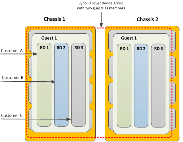
Route domains within a guest
Each route domain contains all of the network objects necessary for processing a specific type of traffic and ensuring failover to the other guest in the event that the system becomes unavailable. These network objects consist of floating self IP addresses associated with host-based VLANs, floating virtual IP addresses, and pool members defined on the guest. The floating addresses are further associated with an active traffic group on one instance of the guest and a standby traffic group on the other instance of the guest.
Prerequisite configuration tasks
Before you begin deploying route domains within a vCMP guest, ensure that you have configured the following on each chassis:
- The initial setup of the BIG-IP® base network on the VIPRION® chassis, prior to provisioning the system for vCMP®. This setup typically includes VLANs for the external and internal networks, as well as an additional internal VLAN for failover communications between device group members.
- The initial setup of the vCMP host. This includes provisioning the system for vCMP and creating guests, with the host VLANs published to the guest.
- Non-floating self IP addresses on the guest. These addresses are associated with the host-based external, internal, and high availability VLANs.
- A Sync-Failover device group consisting of two guests as its members (one guest per chassis). The guests on the two chassis should be identical with respect to memory, CPU, and slot allocation.
About VLAN and BIG-IP address configuration
When you initially configured the BIG-IP® base network on the VIPRION® system, you created three VLANs: two for the internal and external networks, and one for high availability communications, and you created their associated non-floating self IP addresses. Now you are ready to create additional VLANs and self IP addresses for processing each customer's application traffic. On a system provisioned for vCMP®, all VLANs reside on the vCMP host, while all self IP addresses (floating and non-floating) reside on the guest.
Illustration of VLAN and BIG-IP address configuration
This illustration shows the relationship of the VLANs on the host to the IP addresses within each route domain on the guest. Note that in our example, all three customers use the same self IP and virtual IP addresses but with unique route domain IDs. Also note that except for the non-floating self IP addresses in partition Common, the entire configuration is duplicated on the peer guest (not shown).
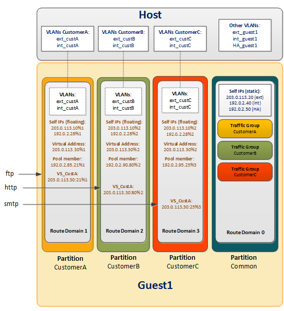
VLANs and BIG-IP addresses in a vCMP route domain configuration
In this illustration:
- Blue text
- Objects created by host administrator.
- Black text
- Objects created by guest administrator.
- Brown text
- Objects created by customer administrator.
Tasks for the host administrator
To set up a route domain configuration, the vCMP® host administrator needs to create VLANs for use by each customer.
On the host, for our sample configuration with three customers, you create a separate set of uniquely-tagged internal and external VLANs for each customer. You will therefore create at least six VLANs on the host (two per customer) that, when combined with the three existing VLANs, bring the total number of VLANs on the host to nine. At this point, all VLANs reside in partition Common. Then you assign all nine host-based VLANs to the guest. This allows the guest to use those VLANs to process customer traffic.
To summarize, the objects that a host administrator creates are:
- VLANs created during base VIPRION® configuration
- Customer-specific VLANs for use by guest route domains
Creating customer VLANs on the vCMP host
You create additional VLANs on the vCMP® host that you then assign to the guest. Then, when logged in to the guest, you can selectively distribute the VLANs to different route domains within the guest. Each route domain corresponds to a different customer.
Assigning VLANs to the vCMP guest
You assign host-based VLANs to a guest so that the guest can use those VLANs to process customer traffic. For the sample configuration, you assign all six customer-specific VLANs to the guest.
Tasks for the guest administrator
You perform the remainder of the configuration on the vCMP® guest. First, you create an administrative partition for each customer. Then from within each customer's partition, you move the relevant customer-specific VLANs from Common to that partition.
Once each customer's VLANs have been moved to the relevant partition, you can create a route domain and a traffic group for each customer.
To summarize, the objects that a guest-wide administrator creates are:
- Administrative partitions
- Instances of host-based customer VLANs
- Route domains
- Traffic groups for failover
Creating an administrative partition for each customer
You perform this task to create administrative partitions within a vCMP® guest. An administrative partition creates an access control boundary for users and applications. Using this task, you create a separate administrative partition for each customer associated with the guest. Each administrative partition will contain a route domain that contains the Layer 3 objects associated with the relevant customer.
About moving host-based VLANs to a customer partition
As guest administrator, you must switch to a specific customer administrative partition and move a customer-related VLAN from Common to that partition. You effectively move each VLAN by deleting the VLAN from Common and re-creating the VLAN in the relevant customer's partition.
For example, if you create route domain 1 in partition A for Customer A's traffic, you will then move VLANs ext_custA and int_custA from Common to partition A. This associates the VLAN with the new partition instead of partition Common, without changing the host's control of the VLAN's underlying Layer 2 (and lower) network resources.
Deleting VLANs in partition Common from within the guest
You use this task to delete a VLAN in partition Common on a guest so that you can re-create the VLAN in a customer partition.
Re-creating VLANs in each administrative partition
You perform this task to re-create a VLAN in a specific customer partition. You re-create a VLAN in a customer partition when you want to set up a route domain configuration within the guest. The VLAN you are re-creating is one that you previously created on the host in partition Common and then deleted from partition Common when you later logged in to the guest. Each route domain that you create in a partition requires you to assign one or more VLANs to that route domain, and those VLANs must reside in the same partition as the route domain.
Creating a route domain for each administrative partition
Creating an empty traffic group for each customer
Perform this task when you want to create a separate floating traffic group for each customer's traffic. You should perform this task on the guest on which you want the traffic groups to be active.
Assigning a traffic group to each administrative partition
You assign an individual traffic group to each customer partition to ensure that when failover occurs, the floating IP addresses defined in the named traffic group fail over to the peer guest and remain associated with the correct administrative partition.
Tasks for each customer administrator
After the vCMP® host and guest administrators have set up the VLANs, partitions, route domains, and traffic groups, the customer administrator logging into the guest creates the necessary IP addresses for the application: internal and external floating self IP addresses, server pool member addresses, and a destination virtual server address. The customer administrator also modifies the floating virtual IP address (associated with the virtual server) to assign the relevant traffic group.
Creating floating self IP addresses
As a customer administrator, you create two floating self IP addresses for each customer route domain, one address for the internal network and one address for the external network.
For example, for customer A's internal and external networks, you create two self IP addresses to which you assign VLANs int_custA and ext_custA respectively, which have both been previously assigned to route domain 1. Similarly, for customer B, you create self IP addresses and assign VLANs int_custB and ext_custB respectively, which have both been previously assigned to route domain 2, and so on.
You also add the self IP addresses as members of a customer-related floating traffic group. This causes the self IP addresses to become floating addresses.
Creating a pool
Creating a virtual server
Modifying a virtual IP address
Implementation results
After you have completed all tasks in this implementation, you have a Device Service Clustering (DSC®) configuration in which one of the guests on each vCMP® system contains three administrative partitions, each of which contains a default route domain with Layer 3 IP addresses pertaining to a specific type of traffic.
With this configuration, the BIG-IP® system can process network traffic for three separate customers. Because each set of addresses for a traffic type is contained in a route domain, all three sets of customer IP addresses can be identical except for the unique route domain ID that is implicitly part of each address.
Furthermore, each route domain is associated with a unique floating traffic group that can fail over to the other guest if the vCMP® system becomes unavailable for any reason.


