Applies To:
Show Versions
BIG-IP AAM
- 12.1.4, 12.1.3, 12.1.2, 12.1.1
BIG-IP APM
- 12.1.6, 12.1.5, 12.1.4, 12.1.3, 12.1.2, 12.1.1
BIG-IP Analytics
- 12.1.6, 12.1.5, 12.1.4, 12.1.3, 12.1.2, 12.1.1
BIG-IP Link Controller
- 12.1.6, 12.1.5, 12.1.4, 12.1.3, 12.1.2, 12.1.1
BIG-IP LTM
- 12.1.6, 12.1.5, 12.1.4, 12.1.3, 12.1.2, 12.1.1
BIG-IP AFM
- 12.1.6, 12.1.5, 12.1.4, 12.1.3, 12.1.2, 12.1.1
BIG-IP PEM
- 12.1.6, 12.1.5, 12.1.4, 12.1.3, 12.1.2, 12.1.1
BIG-IP DNS
- 12.1.6, 12.1.5, 12.1.4, 12.1.3, 12.1.2, 12.1.1
BIG-IP ASM
- 12.1.6, 12.1.5, 12.1.4, 12.1.3, 12.1.2, 12.1.1
Interfaces
Introduction to BIG-IP system interfaces
A key task of the BIG-IP® system configuration is the configuration of BIG-IP system interfaces. The interfaces on a BIG-IP system are the physical ports that you use to connect the BIG-IP system to other devices on the network. These other devices can be next-hop routers, Layer 2 devices, destination servers, and so on. Through its interfaces, the BIG-IP system can forward traffic to or from other network devices.
Every BIG-IP system includes multiple interfaces. The exact number of interfaces that you have on the BIG-IP system depends on the platform type.
A BIG-IP system has two types of interfaces:
- A management interface
- The management interface is a special interface dedicated to performing a specific set of system management functions.
- TMM switch interfaces
- TMM switch interfaces are those interfaces that the BIG-IP system uses to send or receive application traffic, that is, traffic slated for application delivery.
Each of the interfaces on the BIG-IP system has unique properties, such as the MAC address, media speed, duplex mode, and support for Link Layer Discovery Protocol (LLDP).
In addition to configuring interface properties, you can implement a feature known as interface mirroring, which you can use to duplicate traffic from one or more interfaces to another. You can also view statistics about the traffic on each interface.
Once you have configured the properties of each interface, you can configure several other features of the BIG-IP system that control the way that interfaces operate. For example, by creating a virtual local area network (VLAN) and assigning interfaces to it, the BIG-IP system can insert a VLAN ID, or tag, into frames passing through those interfaces. In this way, a single interface can forward traffic for multiple VLANs.
About link layer discovery protocol
The BIG-IP® system supports Link Layer Discovery Protocol (LLDP). LLDP is a Layer 2 industry-standard protocol (IEEE 802.1AB) that enables a network device such as the BIG-IP system to advertise its identity and capabilities to multi-vendor neighbor devices on a network. The protocol also enables a network device to receive information from neighbor devices.
LLDP transmits device information in the form of LLDP messages known as LLDP Data Units (LLDPDUs). In general, this protocol:
- Advertises connectivity and management information about the local BIG-IP device to neighbor devices on the same IEEE 802 LAN.
- Receives network management information from neighbor devices on the same IEEE 802 LAN.
- Operates with all IEEE 802 access protocols and network media.
Using the BIG-IP Configuration utility or tmsh, you can configure the BIG-IP system interfaces to transmit or receive LLDPDUs. More specifically, you can:
- Specify the exact content of LLDPDUs that a BIG-IP system interface transmits to a neighbor device. You specify this content by configuring the LLDP Attributes setting on each individual interface.
- Globally specify the frequencies of various message transmittal properties, and specify the number of neighbors from which each interface can receive messages. These properties apply to all interfaces on the BIG-IP system.
This figure shows a local LLDP-enabled BIG-IP system, configured to both transmit and receive LLDP messages from neighbor devices on a LAN.
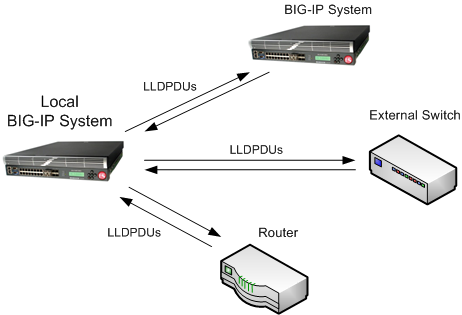
A local BIG-IP system that transmits and receives LLDPDUs
Interface properties
Each interface on the BIG-IP® system has a set of properties that you can configure, such as enabling or disabling the interface, setting the requested media type and duplex mode, and configuring flow control. Configuring the properties of each interface is one of the first tasks you do after running the Setup utility on the BIG-IP system. While you can change some of these properties, such as media speed and duplex mode, you cannot change other properties, such as the media access control (MAC) address.
Before configuring interface properties, it is helpful to understand interface naming conventions. Only users with either the Administrator or Resource Administrator user role can create and manage interfaces.
Interface naming conventions
By convention, the names of the interfaces on the BIG-IP® system use the format <s>.<p> where s is the slot number of the network interface card (NIC), and p is the port number on the NIC. Examples of interface names are 1.1, 1.2, and 2.1. BIG-IP system interfaces already have names assigned to them; you do not explicitly assign them.
An exception to the interface naming convention is the management interface, which has the special name, MGMT.
About interface information and media properties
Using the BIG-IP Configuration utility, you can display a screen that lists all of the BIG-IP® system interfaces, as well as their current status (UP or DOWN). You can also view other information about each interface:
- MAC address of the interface
- Interface availability
- Media type
- Media speed
- Active mode (such as full)
This information is useful when you want to assess the way that a particular interface is forwarding traffic. For example, you can use this information to determine the specific VLANs for which an interface is currently forwarding traffic. You can also use this information to determine the speed at which an interface is currently operating.
Interface state
You can either enable or disable an interface on the BIG-IP® system. By default, each interface is set to Enabled, where it can accept ingress or egress traffic. When you set the interface to Disabled, the interface cannot accept ingress or egress traffic.
Fixed Requested Media
The Fixed Requested Media property shows that the interface auto-detects the duplex mode of the interface.
About flow control
You can configure the way that an interface handles pause frames for flow control. Pause frames are frames that an interface sends to a peer interface as a way to control frame transmission from that peer interface. Pausing a peer’s frame transmissions prevents an interface’s First-in, First-out (FIFO) queue from filling up and resulting in a loss of data. Possible values for this property are:
- Pause None
- Disables flow control.
- Pause TX/RX
- Specifies that the interface honors pause frames from its peer, and also generates pause frames when necessary. This is the default value.
- Pause TX
- Specifies that the interface ignores pause frames from its peer, and generates pause frames when necessary.
- Pause RX
- Specifies that the interface honors pause frames from its peer, but does not generate pause frames.
About the Ether Type property
The Ether Type property appears in the BIG-IP® Configuration utility only when the system includes ePVA hardware support. An ether type is a two-octet field in an Ethernet frame, used to indicate the protocol encapsulated in the payload. The BIG-IP system uses the value of this property when an interface or trunk is associated with a IEEE 802.1QinQ (double tagged) VLAN. By default, the system sets this value to 0x8100.
About the LLDP property
The LLDP property is one of two properties related to LLDP that you can configure for a specific interface. The possible values for this setting are:
- Disabled
- When set to this value, the interface neither transmits (sends) LLDP messages to, nor receives LLDP messages from, neighboring devices.
- Transmit Only
- When set to this value, the interface transmits LLDP messages to neighbor devices but does not receive LLDP messages from neighbor devices.
- Receive Only
- When set to this value, the interface receives LLDP messages from neighbor devices but does not transmit LLDP messages to neighbor devices.
- Transmit and Receive
- When set to this value, the interface transmits LLDP messages to and receives LLDP messages from neighboring devices.
In addition to the LLDP-related settings that you can configure per interface, you can configure some global LLDP settings that apply to all interfaces on the system.
Moreover, you can view statistics pertaining to any neighbor devices that have transmitted LLDP messages to the local BIG-IP® system.
LLDP Attributes
The LLDP Attributes setting is one of two settings related to LLDP that you can configure for a specific interface. You use this interface setting to specify the content of an LLDP message being sent or received. Each LLDP attribute that you specify with this setting is optional and is in the form of Type, Length, Value (TLV).
About interface mirroring
For reliability reasons, you can configure a feature known as interface mirroring. When you configure interface mirroring, you cause the BIG-IP® system to copy the traffic on one or more interfaces to another interface that you specify. By default, the interface mirroring feature is disabled.
Neighbor settings
When a BIG-IP® system interface receives LLDP messages from neighbor devices, the BIG-IP system displays chassis, port, and system information about the content of those messages. Specifically, the system displays values for the standard TLVs for each neighbor. These TLVs are:
- Chassis ID
- Identifies the chassis containing the IEEE 802 LAN station associated with the transmitting LLDP agent.
- Port ID
- Identifies the port component of the media service access point (MSAP) identifier associated with the transmitting LLDP agent.
- Port description
- An alpha-numeric string that describes the interface.
- System name
- An alpha-numeric string that indicates the administratively-assigned name of the neighbor device.
- System description
- An alpha-numeric string that is the textual description of the network entity. The system description should include the full name and version identification of the hardware type, software operating system, and networking software of the neighbor device.
- System capabilities
- The primary functions of the system and whether these primary functions are enabled.
- Management address
- An address associated with the local LLDP agent used to reach higher layer entities. This TLV might also include the system interface number that is associated with the management address, if known.
Configuring settings for an interface
Related configuration tasks
After you have configured the interfaces on the BIG-IP® system, one of the primary tasks you perform is to assign those interfaces to the virtual LANs (VLANs) that you create. A VLAN is a logical subset of hosts on a local area network (LAN) that reside in the same IP address space. When you assign multiple interfaces to a single VLAN, traffic destined for a host in that VLAN can travel through any one of these interfaces to reach its destination. Conversely, when you assign a single interface to multiple VLANs, the BIG-IP system can use that single interface for any traffic that is intended for hosts in those VLANs.
Another powerful feature that you can use for BIG-IP system interfaces is trunking, with link aggregation. A trunk is an object that logically groups physical interfaces together to increase bandwidth. Link aggregation, through the use of the industry-standard Link Aggregation Control Protocol (LACP), provides regular monitoring of link status, as well as failover if an interface becomes unavailable.
Finally, you can configure the BIG-IP system interfaces to work with one of the spanning tree protocols (STP, RSTP, and MSTP). Spanning tree protocols reduce traffic on your internal network by blocking duplicate routes to prevent bridging loops.


