Manual Chapter : Managing Event Logs in Access

Applies To:

Show Versions Show Versions

BIG-IQ Centralized Management

  • 5.0.0
Manual Chapter

Managing Event Logs for BIG-IQ Access

How do I manage event logs with a Logging Node?

Viewing the event logs as implemented on BIG-IQ® eases browsing of system event logs, and provides a way to obtain useful insights regarding the activity on applications and/or servers. The BIG-IQ platform enables a single view of all filters and log entries (and details for each entry) from multiple BIG-IP® devices.

It also provides a more intuitive navigation path through the log items.

To properly configure event log viewing:
  • Discover and activate a BIG-IQ Logging Node.
  • License and provision a BIG-IQ Logging Node.
  • Define an external machine to which periodic data snapshots are sent.
  • Configure a BIG-IP system to collect event logs and send them to the BIG-IQ Logging Node. Part of this configuration includes a virtual server configured with a logging profile.
  • Configure a logging profile on BIG-IQ, assign it to a virtual server, and deploy it to the BIG-IP device that has been configured to collect log events.

    A logging profile is used to determine which events the system logs, and where, and the format of these events. It then directs security events to a BIG-IQ Logging Node, and the BIG-IQ system retrieves them from that node.

Logging Node uses a search engine that requires separate services for management and traffic. Keeping those services on separate networks reduces unnecessary congestion. The network designs described here are not required, but considered best practice.

BIG-IQ Networks

  • A cluster management network to perform Elasticsearch configuration and status operations
  • A cluster traffic network for inter-node communication

Logging Node Networks

  • A cluster management network to perform Elasticsearch configuration and status operations
  • A cluster traffic network for inter-node communication
  • A listener network to handle inbound data traffic

This figure illustrates the network topology required to deploy a logging node for your event logs.

Change managed object workflow

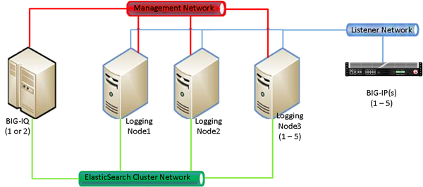
Logging Node network topology

Important: F5 Networks strongly recommends that the Listener Network and Management Networks be separate. This separation, can help with data protection and management network availability in case the Listener Network is flooded with data.

What is a BIG-IQ Logging Node?

A BIG-IQ Logging Node is a specially-provisioned BIG-IQ® system, that runs the same software version as the BIG-IQ device that you use to manage your security, and the rules that determine your alert responses. After you provision the BIG-IQ Logging Node, you discover it from BIG-IQ and then add the service. Once you configure a logging profile, the Logging Node stores events related to security and application policies from one or more BIG-IP® systems. The BIG-IQ system can then retrieve and manage those logging events.

Note: The software version on the Logging Node must be the same as the version on its partner BIG-IQ system. If you need to upgrade the Logging Node, follow the instructions in Upgrading BIG-IQ Systems.

Discovering and activating a logging node

Using BIG-IQ® System Management, you can discover a Logging Node and add it to the Logging Group. The BIG-IQ can then access all event on the discovered Logging Node. You can then collect these event from multiple BIG-IP® systems. This unified view makes browsing easier, and provides a complete view of application event activity.
  1. Log in to BIG-IQ system with your administrator user name and password.
  2. At the top left of the screen, select System Management from the BIG-IQ menu.
  3. On the left, expand BIG-IQ LOGGING.
  4. Under BIG-IQ LOGGING, select Logging Nodes.
  5. Click Add Node.
  6. On the New Logging Device screen, fill in as appropriate:
    1. In IP Address, type the management IP address.
    2. In User Name, type the user name for an administrator on the Logging Node (for example, admin.
    3. In Password, type the password for an administrator on the Logging Node (for example, admin.
    4. In Transport Address, type the IP address of the logging node internal self IP address.
    5. For Transport Port, the default value is 9300. The BIG-IQ uses this port for internal polling and communication with the logging nodes.
  7. Click the Add button at the bottom of the screen to add the Logging Node to the system. Or, click Discard to cancel the operation.
    Note: This operation might take a minute or two.
  8. Repeat these 7 steps for each Logging Node you want to configure.
  9. To activate this logging node for the service you want to monitor, in the Services column, click Add Services.
    The Logging Node Services screen opens.
  10. For the service you want to add, confirm that the Listener Address correctly specifies the external self IP address of the Logging Node, and click Activate.
    When the service is successfully added, the Service Status changes to Active.
  11. Click Close.
Once discovered and activated, this logging node collects the event generated by the configured BIG-IP systems. Thus, BIG-IQ provides a single view of all event log entries.
Important: The Total Document Count is not a report of the number of alerts sent to the Logging Node. Instead, it is a sum of various document types sent to the Logging Node. Alerts are included in this list, but this total includes other document types as well.

Modifying event log indices

Event log indices determine the physical characteristics of what is sent to the Logging Node.
  1. Log in to the BIG-IQ® system with your user name and password.
  2. At the top left of the screen, select System Management from the BIG-IQ menu.
  3. On the left, select Logging Configuration.
    The Logging Configuration screen opens to display the current state of the logging node cluster defined for this device.
  4. In the Access row in the bottom half of the screen, click the Configure button.
    The Access Indices screen opens.
  5. For the Rotation Type, keep the default setting: Size Based.
  6. For the Max Index Size, type the maximum size of the indices you want to send to the logging node.
    For example, if you type 1000, when the event log data reaches a size of 1 Gig, it is sent to the logging node.
  7. For the Retained Index Count, type the total number of indexes you want to store on the logging node.
    The maximum amount of data stored on the Logging Node is the product of the Max Index Size and the Retained Index Count. When the amount of data reaches this size, the oldest event log data is overwritten.
  8. Click Save to save the indices configuration settings.

Defining event log snapshot storage locations

Before you can configure the snapshot storage location, you need the following information on the machine you will use to store the event log snapshots:
  • storage-machine-IP-address
  • storage-file-path
  • Read/Write permissions for the storage file path

You need snapshots of indices and alert data to perform software upgrades, hotfix upgrades, and alert restoration for FPS.

When event log snapshots are created, they need to be stored on a machine other than the Logging Node that stores the event logs. You define the location for the snapshot by editing the fstab file on your Logging Node machines and on the BIG-IQ® and HA peer devices.

Important: You must perform this task on each Logging Node device, on the BIG-IQ device, and on the BIG-IQ HA peer.
  1. On the first device, in the folder /var/config/rest/elasticsearch/data/, create a new folder named essnapshot.
    mkdir /var/config/rest/elasticsearch/data/essnapshot
  2. Edit the /etc/fstab file to add /var/config/rest/elasticsearch/data/essnapshot.
    For example, //<storage machine ip-address>/<storage-file-path>/var/config/rest/elasticsearch/data/essnapshot cifs iocharset=utf8,rw,noauto,uid=elasticsearch,gid=elasticsearch, 0 0
  3. Run the mount command to mount the snapshot storage location to the new folder.
    For example, from /var/config/rest/elasticsearch/data type: mount essnapshot.
  4. Confirm that the essnapshot folder has full read, write and execute permissions, (specifically Chmod 777 essnapshot), and that the owner and group are elasticsearch for this folder.
    For example, ls-l would yield: drwxrwxrwx 3 elasticsearch elasticsearch 0 Apr 25 11:27 essnapshot.
  5. Create a test file to confirm that the storage file-path has been successfully mounted.
    For example: touch testfile.
    The test file should be created on the storage machine at the location storage file path.
  6. Repeat these five steps for each Logging Node, the BIG-IQ, and the BIG-IQ HA peer.
The storage location should now be accessible to the BIG-IQ devices and to the logging node machines.

Defining event log database snapshot schedules

Before you define snapshot schedules, you must have defined the snapshot storage locations.
Snapshots of the event logs sent to your Logging Nodes are an essential safeguard for your data. If the machine that stores the event logs fails, the data can be restored using these snapshots. These snapshots are created based on the snapshot schedules you define. F5 recommends that you schedule snapshots at least every 6 hours and retain at least 4 snapshots.
  1. Log in to BIG-IQ system with your administrator user name and password.
  2. At the top left of the screen, select System Management from the BIG-IQ menu.
  3. On the left, expand BIG-IQ LOGGING.
  4. Under BIG-IQ LOGGING, select Logging Configuration.
  5. For the Snapshot Schedules setting, click Create.
    The New Logging Snapshot screen opens.
  6. For the Snapshot Name Prefix, type the string that you want to use to identify the snapshots created by this schedule.
    For example snapshot_.
  7. In Snapshots to Keep, specify the number of snapshots that you want to accumulate before they are deleted for space constraints.
    For example, if you specify 25, then the system will retain a maximum of 25 snapshots before it starts to delete older snapshots as new snapshots are created. You can save up to 100.
  8. Define how you want the snapshots scheduled.
    Option Description
    Schedule the interval at which you want to create snapshots:

    You schedule the system to take snapshots indefinitely. Snapshots are created at the frequency you specify.

    1. Select Repeat Interval.
    2. Specify the Snapshot Frequency.
    3. Select a time increment.

    For example, if you set the frequency to 6 and Hours, the first log event data snapshot is taken immediately (on Save). Subsequent snapshots are taken every 6 hours.

    Schedule specific days on which you want to create snapshots:

    You schedule the system to take snapshots on specific days.

    1. Select Days of the Week.
    2. For the Days of the Week setting, select the days on which you want backups to occur.
    3. For the Start Date, select the time (date, hour, minute, and AM or PM) on which you want backups to start.
  9. Click Save to save the new schedule.

How do I license and do the basic setup to start using a Logging Node?

The BIG-IQ® Logging Node runs as a virtual machine in supported hypervisors, or on the BIG-IQ 7000 series platform. You license the Logging Node using the base registration key you purchased. The base registration key is a character string that the F5 license server uses to provide access to Logging Node features.

You license Logging Node in one of the following ways:

  • If the system has access to the internet, you can have the Logging Node contact the F5 license server and automatically activate the license.
  • If the system is not connected to the internet, you can manually retrieve the activation key from a system that is connected to the internet, and transfer it to the Logging Node.
  • If your Logging Node is in a closed-circuit network (CCN) that does not allow you to export any encrypted information, you must open a case with F5 support.

When you license the Logging Node, you:

  • Specify a host name for the system.
  • Assign a management port IP address.
  • Specify the IP address of your DNS server and the name of the DNS search domain.
  • Specify the IP address of your Network Time Protocol (NTP) servers and select a time zone.
  • Change the administrator’s default admin and root passwords.
Automatically licensing BIG-IQ and performing initial setup
You must have a base registration key before you can license the BIG-IQ® system. If you do not have a base registration key, contact the F5 Networks sales group (http://www.f5.com).
If the BIG-IQ® system is connected to the public internet, you can follow these steps to automatically perform the initial license activation and perform the initial setup.
  1. Use a browser to log in to BIG-IQ by typing https://<varname><management_IP_address><varname>, where <management_IP_address> is the address you specified for device management.
  2. Log in to the BIG-IQ® system with your user name and password.
  3. Click Activate.
    The Base Registration Key field is added to the screen.
  4. In the Base Registration Key field, type or paste the BIG-IQ registration key.
    Important: The registration key you use must support a Logging Node capable license.
  5. In the Add-On Keys field, paste any additional license key you have.
  6. To add another additional add-on key, click the + sign and paste the additional key in the new Add-On Keys field.
  7. For the Activation Method setting, select Automatic, and click the Activate License button.
    The End User Software License Agreement (EULA) displays.
  8. To accept the license agreement, click the Agree button.
  9. Click the Next button at the right of the screen.
    If the license you purchased supports both Logging Node and BIG-IQ Central Management Console, the License Feature Selection popup screen opens. Otherwise the Management Address screen opens.
  10. If you are prompted with the License Feature Selection, select BIG-IQ Logging Node, and then click OK. If you are not prompted, proceed to the next step.
    Important: This choice cannot be undone. Once you license a device as a Logging Node, you cannot change your mind and license it as a BIG-IQ Management Console.
    The Management Address screen opens.
  11. In the Host Name field, type a fully-qualified domain name (FQDN) for the system.
    You cannot change this name after you add it. The FQDN can consist of letters and numbers, as well as the characters underscore ( _ ), dash ( - ), or period ( . ).
  12. In the Management Port IP Address field, type the IP address for the management port IP address.
    Note: The management port IP address must be in Classless Inter-Domain Routing (CIDR) format. For example: 10.10.10.10/24.
  13. In the Management Port Route field that the system creates, type the IP address for the management port route.
  14. Specify what you want the BIG-IQ to use for the Discovery Address.
    • To use the management port, select Use Management Address.
    • To use the internal self IP address, select Self IP Address, and type the IP address.
      Important: If you are configuring a Logging Node device, you must use the internal self IP address.
      Note: The self IP address must be in Classless Inter-Domain Routing (CIDR) format. For example: 10.10.10.10/24.
  15. Click the Next button at the right of the screen.
  16. In the DNS Lookup Servers field, type the IP address of your DNS server.
    You can click the Test Connection button to verify that the IP address is reachable.
  17. In the DNS Search Domains field, type the name of your search domain.
    The DNS search domain list allows the BIG-IQ system to search for local domain lookups to resolve local host names.
  18. In the Time Servers fields, type the IP addresses of your Network Time Protocol (NTP) servers.
    You can click the Test Connection button to verify that the IP address is reachable.
  19. From the Time Zone list, select your local time zone.
  20. Click the Next button at the right of the screen.
  21. In the Old Password fields, type the default admin and root passwords, and then type a new password in the Password and Confirm Password fields.
  22. Click the Next button at the right of the screen.
Manually licensing BIG-IQ and performing initial setup
You must have a base registration key before you can license the BIG-IQ® system. If you do not have a base registration key, contact the F5 Networks sales group (http://www.f5.com).
If the BIG-IQ® system is not connected to the public internet, use this procedure to manually activate the license and perform the initial setup.
  1. Use a browser to log in to BIG-IQ by typing https://<varname><management_IP_address><varname>, where <management_IP_address> is the address you specified for device management.
  2. Log in to the BIG-IQ® system with your user name and password.
  3. Click Activate.
    The Base Registration Key field is added to the screen.
  4. In the Base Registration Key field, type or paste the BIG-IQ registration key.
    Important: The registration key you use must support a Logging Node capable license.
  5. In the Add-On Keys field, paste any additional license key you have.
  6. For the Activation Method setting, select Manual and click the Generate Dossier button.
    The BIG-IQ system refreshes and displays the dossier in the Device Dossier field.
  7. Select and copy the text displayed in the Device Dossier field.
  8. Click the Access F5 manual activation web portal link.
    The Activate F5 Product site opens.
  9. Into the Enter your dossier field, paste the dossier.
    Alternatively, if you saved the file, click the Choose File button and navigate to it.
    After a pause, the license key text displays.
  10. Click the Next button.
    The Accept User Legal Agreement screen opens.
  11. To accept the license agreement, select the I have read and agree to the terms of this license, and click Next. button.
    The licensing server creates the license key text.
  12. Copy the license key.
  13. In the License Text field on BIG-IQ, paste the license text.
  14. Click the Activate License button.
  15. Click the Next button at the right of the screen.
    If the license you purchased supports both Logging Node and BIG-IQ Central Management Console, the License Feature Selection popup screen opens. Otherwise the Management Address screen opens.
  16. If you are prompted with the License Feature Selection, select BIG-IQ Logging Node, and then click OK. If you are not prompted, proceed to the next step.
    Important: This choice cannot be undone. Once you license a device as a Logging Node, you cannot change your mind and license it as a BIG-IQ Management Console.
    The Management Address screen opens.
  17. In the Host Name field, type a fully-qualified domain name (FQDN) for the system.
    You cannot change this name after you add it. The FQDN can consist of letters and numbers, as well as the characters underscore ( _ ), dash ( - ), or period ( . ).
  18. In the Management Port IP Address field, type the IP address for the management port IP address.
    Note: The management port IP address must be in Classless Inter-Domain Routing (CIDR) format. For example: 10.10.10.10/24.
  19. In the Management Port Route field that the system creates, type the IP address for the management port route.
  20. Specify what you want the BIG-IQ to use for the Discovery Address.
    • To use the management port, select Use Management Address.
    • To use the internal self IP address, select Self IP Address, and type the IP address.
      Important: If you are configuring a Logging Node device, you must use the internal self IP address.
      Note: The self IP address must be in Classless Inter-Domain Routing (CIDR) format. For example: 10.10.10.10/24.
  21. Click the Next button to save your configuration.
  22. In the DNS Lookup Servers field, type the IP address of your DNS server.
    You can click the Test Connection button to verify that the IP address is reachable.
  23. In the DNS Search Domains field, type the name of your search domain.
    The DNS search domain list allows the BIG-IQ system to search for local domain lookups to resolve local host names.
  24. In the Time Servers fields, type the IP addresses of your Network Time Protocol (NTP) servers.
    You can click the Test Connection button to verify that the IP address is reachable.
  25. From the Time Zone list, select your local time zone.
  26. Click the Next button at the right of the screen.
  27. In the Old Password fields, type the default admin and root passwords, and then type a new password in the Password and Confirm Password fields.
  28. Click the Next button at the right of the screen.

Configuring remote logging

BIG-IP® devices that you configure for remote logging send Access reporting and SWG log report data to the BIG-IQ® Logging Node for storage and management.
  1. Log in to BIG-IQ system with your administrator user name and password.
  2. At the top left of the screen, select Access from the BIG-IQ menu.
  3. At the top of the screen, click Access Reporting.
  4. On the left, expand REMOTE LOGGING CONFIGURATION and click Logging Profiles.
    The Remote Logging Configuration screen opens to display all of the discovered BIG-IP devices that are provisioned with the Access service.
  5. Select the BIG-IP devices for which you want to enable remote logging, and then click Configure.
    The hostname of the primary logging node is displayed, and the status changes to let you know whether the enable request was successful.

Restoring event log database snapshots

To submit the REST API calls required by this task, you must provide the administrator user name and password.

The BIG-IQ® user interface does not currently support restoring the event log snapshots. However, if a logging node fails, you can manually restore the data up to the last snapshot.

Please note the following:

  • The restore operation requires a down time during which no BIG-IQ or Logging Node work is performed.
  • During the restore operation, no event log data sent to the Logging Node is retained.
  • The restore operation restores only the data from the chosen snapshot. Data from the chosen snapshot to the current time is not restored.
  • The restore operation restores only the data from the chosen snapshot. Data from the chosen snapshot to the current time is not restored.
  • Before initiating a snapsnot restore, make sure that sufficient disk space is allocated to the /var folder on the device to which you are restoring the snapshot.
  1. Log in to BIG-IQ system with your administrator user name and password.
  2. At the top left of the screen, select System Management from the BIG-IQ menu.
  3. On the left, expand BIG-IQ LOGGING and select Logging Configuration.
    The Logging Configuration screen opens.
  4. Click the View History button.
    The BIG-IQ Logging Snapshots screen opens.
  5. Browse through the list to get an idea of which snapshot you want to restore.
  6. From a browser window, use a REST API request to get the list of available snapshots retained by the system.
    For example,
    GET: https://<BIG-IQ Machine Address>/mgmt/cm/shared/esmgmt/es-snapshots?$orderby=snapshotDateTime desc
                        
    The GET request returns a list of snapshots from which data can be restored. The most recent snapshots are listed first.
  7. Determine which snapshot you want to restore from the returned list. Identify the selfLink of the snapshot that you want.
  8. From a browser window, use a REST API POST request to initiate the restore.
    For example:
            POST:
            https://<BIG-IQ Machine Address>/BIG-IQ/mgmt/cm/shared/esmgmt/es-restore-task
            {
            "snapshotReference" : {
                "link": "<paste the selfLink selected in Step #6 here>"
      		    }
      		 }
      		 
    The restore process begins. The time it takes to perform this process depends on the size of the snapshot, but assume at least 10 minutes.
  9. To determine when the restore operation is complete, monitor the restjavad.0.log file (using a tail command).
    For example:
    tail -f /var/log/restjavad.0.log
    When the message ES Restore completed successfully displays, the BIG-IQ and Logging Node are again ready to resume operation.
  10. After the restore is completed, log in to each logging node and restart the restjavad process.
    For example:
    restart restjavad

Logging Node management

There are a number of useful concepts to consider when you manage Logging Nodes for off-box log storage. This reference material might prove helpful in setting up and maintaining your Logging Node configuration.

Logging Node sizing guide

Logging Nodes are specialized BIG-IQ® devices designed to provide sufficient CPU, memory, and disk capacity to store and search logging data from BIG-IP® devices. The underlying technology to provide these services is Elasticsearch. (Information about general Elasticsearch comments can be found on their website: https://www.elastic.co/guide/en/elasticsearch/reference/current/_basic_concepts.html)

Logging Nodes managed by BIG-IQ provide an Elasticsearch (ES) cluster that can scale horizontally (more nodes = more capacity), but each node in that cluster has limits on disk space. To mitigate that, there are a number of configuration elements that control how much disk is used by the system.

Logging Node Minimum Recommended Configuration
CPU 8 Cores
Memory 32 GB
Disk 10 GB (/var file system )

The /var file system on the Logging Node (which includes ES data) is only 10GB in size. To store more data on the file system , you need to extend the size. Refer to Index rotation policy for details on managing the data requirements. Extending the file system to 500GB is straightforward, assuming overall disk allocation on the BIG-IQ virtual machine is adequate. Log in as root to the Logging Node, and run the following commands.

  1. tmsh show sys disk directory

    The system response will be similar to this:

    Directory Name                  Current Size    New Size
    --------------                  ------------    --------
    /config                         1048576         -
    /shared                         10240000        -
    /var                            10485760        -
    /var/log                        7168000         -
            
  2. tmsh modify sys disk directory /var new-size 100000000

    tmsh show sys disk directory

    The system response will be similar to this:

    Directory Name                  Current Size    New Size
    --------------                  ------------    --------
    /config                         1048576         -
    /shared                         10240000        -
    /var                            10485760        500000000
    /var/log                        7168000         -
            
  3. Reboot the system. and then confirm the size disk size.

    tmsh show sys disk directory

    The system response will be similar to this:

    Directory Name                  Current Size    New Size
    --------------                  ------------    --------
    /config                         1048576         -
    /shared                         10240000        -
    /var                            500003840       -
    /var/log                        7168000         -
            
Index rotation policy

The optimum settings used to configure your logging node indices depend on a number of factors. Some of the key factors are discussed here.

The system provides the ability to dynamically create new indices based either on a specified interval or on a specified size. The primary goal to consider when you make these decisions is how to maintain a maximum disk allocation for the Logging Node data while maintaining capacity for new data that flows in.

Secondary considerations include search optimization, and the ability to optimize old indices to reduce their size.

Generally, the best policy is one that does not create unnecessary indices. The more indices, the lower the overall performance, because your searches have to deal with more shards. For example, if a module knows that it has a low indexing volume (thousands/day) then it makes the most sense to have a large aggregation per rotation (5 days or 30 days). For modules like ASM™ that probably have high indexing volumes, it makes more sense to rotate every 8 hours (which reduces the number of retained indices).

Index rotation also allows changing sharding and replica counts by changing the template on a given index type. New indices created from that template will contain the new shard and replica count properties.

This table shows the default configuration values for each index running on the BIG-IQ®. These values are based on anticipated data ingestion rates and typical usage patterns.

Module Index Name Minimum Number of Logging Nodes Rotation Policy Retained Index Count Approximate time window Size of /var file system
Access access-event-logs 2 Time/5 days 19 95 days 500 GB
Access access-stats 2 Time/5 days 19 95 days 500 GB
ASM asmindex 5 Size/100000 MB 5 N/A 500 GB
FPS websafe 2 Time/30 days 100 8 years 10 GB

If multiple modules are running on a given Logging Node or if you have higher inbound data rates, you might have to adjust these values to keep the /var file system from filling up (there is a default alert to warn of this when the file system becomes 80% full).

The simplest resolution is to revise the retained index count; lowering this value will reduce the disk space requirements but it will also reduce the amount of data available for queries. For details on changing this setting, refer to Modifying event log indices.

Managing Configuration Snapshots

What is snapshot management?

You can manage configuration snapshots for the configurations you have created on the BIG-IQ®. A snapshot is a backup copy of a configuration. Configuration snapshots are created automatically during the deployment process, and can also be created manually. This type of snapshot does not include events.

Comparing snapshots

You can compare two snapshots to view their differences.

  1. Log in to the BIG-IQ® system with your user name and password.
  2. At the top left of the screen, select Change Management from the BIG-IQ menu.
  3. Under SNAPSHOT & RESTORE, select Access.
    The screen displays a list of Access snapshots that have been created on this device.
  4. Select the check box to the left of each of the two snapshots to be compared.
  5. Click Compare.
    The Differences screen opens.
  6. Analyze the configuration differences between the two snapshots, When you are finished, click Cancel to close the Differences screen, then click Close.
    The screen closes and you return to the Snapshot and Restore - screen.